Gt3112931298
•
0 gefällt mir•298 views

IJERA (International journal of Engineering Research and Applications) is International online, ... peer reviewed journal. For more detail or submit your article, please visit www.ijera.com

Empfohlen
Weitere ähnliche Inhalte
Was ist angesagt?
Was ist angesagt? (18)
Andere mochten auch
Ähnlich wie Gt3112931298
Ähnlich wie Gt3112931298 (20)
Kürzlich hochgeladen
Kürzlich hochgeladen (20)
Gt3112931298
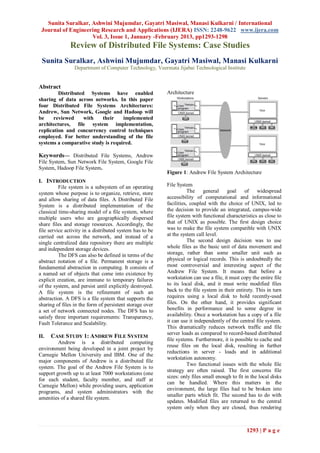
- 1. Sunita Suralkar, Ashwini Mujumdar, Gayatri Masiwal, Manasi Kulkarni / International Journal of Engineering Research and Applications (IJERA) ISSN: 2248-9622 www.ijera.com Vol. 3, Issue 1, January -February 2013, pp1293-1298 Review of Distributed File Systems: Case Studies Sunita Suralkar, Ashwini Mujumdar, Gayatri Masiwal, Manasi Kulkarni Department of Computer Technology, Veermata Jijabai Technological Institute Abstract Distributed Systems have enabled Architecture sharing of data across networks. In this paper four Distributed File Systems Architectures: Andrew, Sun Network, Google and Hadoop will be reviewed with their implemented architectures, file system implementation, replication and concurrency control techniques employed. For better understanding of the file systems a comparative study is required. Keywords— Distributed File Systems, Andrew File System, Sun Network File System, Google File System, Hadoop File System. Figure 1: Andrew File System Architecture I. INTRODUCTION File system is a subsystem of an operating File System system whose purpose is to organize, retrieve, store The general goal of widespread and allow sharing of data files. A Distributed File accessibility of computational and informational System is a distributed implementation of the facilities, coupled with the choice of UNIX, led to classical time-sharing model of a file system, where the decision to provide an integrated, campus-wide multiple users who are geographically dispersed file system with functional characteristics as close to share files and storage resources. Accordingly, the that of UNIX as possible. The first design choice file service activity in a distributed system has to be was to make the file system compatible with UNIX carried out across the network, and instead of a at the system call level. single centralized data repository there are multiple The second design decision was to use and independent storage devices. whole files as the basic unit of data movement and The DFS can also be defined in terms of the storage, rather than some smaller unit such as abstract notation of a file. Permanent storage is a physical or logical records. This is undoubtedly the fundamental abstraction in computing. It consists of most controversial and interesting aspect of the a named set of objects that come into existence by Andrew File System. It means that before a explicit creation, are immune to temporary failures workstation can use a file, it must copy the entire file of the system, and persist until explicitly destroyed. to its local disk, and it must write modified files A file system is the refinement of such an back to the file system in their entirety. This in turn abstraction. A DFS is a file system that supports the requires using a local disk to hold recently-used sharing of files in the form of persistent storage over files. On the other hand, it provides significant a set of network connected nodes. The DFS has to benefits in performance and to some degree in satisfy three important requirements: Transparency, availability. Once a workstation has a copy of a file Fault Tolerance and Scalability. it can use it independently of the central file system. This dramatically reduces network traffic and file server loads as compared to record-based distributed II. CASE STUDY 1: ANDREW FILE SYSTEM file systems. Furthermore, it is possible to cache and Andrew is a distributed computing reuse files on the local disk, resulting in further environment being developed in a joint project by reductions in server - loads and in additional Carnegie Mellon University and IBM. One of the workstation autonomy. major components of Andrew is a distributed file Two functional issues with the whole file system. The goal of the Andrew File System is to strategy are often raised. The first concerns file support growth up to at least 7000 workstations (one sizes: only files small enough to fit in the local disks for each student, faculty member, and staff at can be handled. Where this matters in the Carnegie Mellon) while providing users, application environment, the large files had to be broken into programs, and system administrators with the smaller parts which fit. The second has to do with amenities of a shared file system. updates. Modified files are returned to the central system only when they are closed, thus rendering 1293 | P a g e
- 2. Sunita Suralkar, Ashwini Mujumdar, Gayatri Masiwal, Manasi Kulkarni / International Journal of Engineering Research and Applications (IJERA) ISSN: 2248-9622 www.ijera.com Vol. 3, Issue 1, January -February 2013, pp1293-1298 record-level updates impossible. This is a view of the shared space. The convention is to fundamental property of the design. However, it is configure the system to have a uniform name space. not a serious problem in the university computing By mounting a shared file system over user home environment. The main application for record-level directories on all the machines, a user can log in to updates is databases. Serious multi-user databases any workstation and get his or her home have many other requirements (such as record- or environment. Thus, user mobility can be provided, field-granularity authorization, physical disk write although again by convention. ordering controls, and update serialization) which Subject to access rights accreditation, are not satisfied by UNIX file system semantics, potentially any file system or a directory within a even in a non-distributed environment. file system can be remotely mounted on top of any The third and last key design decision in the local directory. In the latest NFS version, diskless Andrew File System was to implement it with many workstations can even mount their own roots from relatively small servers rather than a single large servers (Version 4.0, May 1988 described in Sun machine. This decision was based on the desire to Microsystems Inc. . In previous NFS versions, a support growth gracefully, to enhance availability diskless workstation depends on the Network Disk (since if any single server fails, the others should (ND) protocol that provides raw block I/O service continue), and to simplify the development process from remote disks; the server disk was partitioned by using the same hardware and operating system as and no sharing of root file systems was allowed. the workstations. At the present time, an Andrew. One of the design goals of NFS is to provide file file server consists of a workstation with three to six services in a heterogeneous environment of different 400-megabyte disks attached. A price/performance machines, operating systems, and network goal of supporting at least 50 active workstations per architecture. The NFS specification is independent file server is acheived, so that the centralized costs of these media and thus encourages other of the file system would be reasonable. In a large implementations. configuration like the one at Carnegie Mellon, a This independence is achieved through the separate "system control machine" to broadcast use of RPC primitives built on top of an External global information (such as where specific users' Date Representation (XDR) protocol-two files are to be found) to the file servers is used. In a implementation independent interfaces [Sun small configuration the system control machine is Microsystems Inc. 19881. Hence, if the system combined with a (the) server machine. consists of heterogeneous machines and file systems that are properly interfaced to NFS, file systems of III. CASE STUDY 2: SUN NETWORK FILE different types can be mounted both locally and SYSTEM remotely. NFS views a set of interconnected workstations as a set of independent machines with Architecture independent file systems. The goal is to allow some In general, Sun’s implementation of NFS is degree of sharing among these file systems in a integrated with the SunOS kernel for reasons of transparent manner. Sharing is based on server-client efficiency (although such integration is not strictly relationship. A machine may be, and often is, both a necessary). client and a server. Sharing is allowed between any pair of machines, not only with dedicated server machines. Consistent with the independence of a machine is the critical observation that NFS sharing of a remote file system affects only the client machine and no other machine. Therefore, there is no notion of a globally shared file system as in Locus, Sprite, UNIX United, and Andrew. To make a remote directory accessible in a transparent manner from a client machine, a user of that machine first has to carry out a mount operation. Actually, only a superuser can invoke the mount operation. Specifying the remote directory as an Figure 2: Schematic View of NFS Architecture argument for the mount operation is done in a nontransparent manner; the location (i.e., hostname) The NFS architecture is schematically of the remote directory has to be provided. From depicted in Figure 6. The user interface is the UNIX then on, users on the client machine can access files system calls interface based on the Open, Read, in the remote directory in a totally transparent Write, Close calls, and file descriptors. This manner, as if the directory were local. Since each interface is on top of a middle layer called the machine is free to configure its own name space, it is Virtual File System (VFS) layer. The bottom layer is not guaranteed that all machines have a common the one that implements the NFS protocol and is 1294 | P a g e
- 3. Sunita Suralkar, Ashwini Mujumdar, Gayatri Masiwal, Manasi Kulkarni / International Journal of Engineering Research and Applications (IJERA) ISSN: 2248-9622 www.ijera.com Vol. 3, Issue 1, January -February 2013, pp1293-1298 called the NFS layer. These layers comprise the NFS are created once but read many times. The GFS is software architecture. The figure also shows the optimized to run on computing clusters where the RPC/XDR software layer, local file systems, and the nodes are cheap computers. Hence, there is a need network and thus can serve to illustrate the for precautions against the high failure rate of integration of a DFS with all these components. The individual nodes and data loss. VFS serves two important functions: It separates file system generic operations Motivation for the GFS Design: from their implementation by defining a clean The GFS was developed based on the following interface. Several implementations for the VFS assumptions: interface may coexist on the same machine, allowing a. Systems are prone to failure. Hence there is a transparent access to a variety of types of file need for self monitoring and self recovery from systems mounted locally (e.g., 4.2 BSD or MS- failure. DOS). b. The file system stores a modest number of large The VFS is based on a file representation files, where the file size is greater than 100 MB. structure called a unode, which contains a numerical c. There are two types of reads: Large streaming designator for a file that is networkwide unique. reads of 1MB or more. These types of reads are from (Recall that UNIXi- nodes are unique only within a a contiguous region of a file by the same client. The single file system.) The kernel maintains one vnode other is a set of small random reads of a few KBs. structure for each active node (file or directory). d. Many large sequential writes are performed. The Essentially, for every file the vnode structures writes are performed by appending data to files and complemented by the mount table provide a pointer once written the files are seldom modified. to its parent file system, as well as to the file system e. Need to support multiple clients concurrently over which it is mounted. Thus, the VFS appending the same file. distinguishes local files from remote ones, and local files are further distinguished according to their file Architecture system types. The VFS activates file system specific Master – Chunk Servers – Client operations to handle local requests according to their A GFS cluster consists of a single master file system types and calls the NFS protocol and multiple chunkservers and is accessed by procedures for remote requests. File handles are multiple clients. Files are divided into fixed-size constructed from the relevant vnodes and passed as chunks. Each chunk is identified by an immutable arguments to these procedures. and globally unique 64 bit chunk handle assigned by As an illustration of the architecture, let us the master at the time of chunk creation. trace how an operation on an already open remote Chunkservers store chunks on local disks as Linux file is handled (follow the example in Figure 6). The files and read or write chunk data specified by a client initiates the operation by a regular system call. chunk handle and byte range. The operating system layer maps this call to a VFS For reliability, each chunk is replicated on operation on the appropriate vnode. The VFS layer multiple chunkservers. By default, we store three identifies the file as a remote one and invokes the replicas, though users can designate different appropriate NFS procedure. An RPC call is made to replication levels for different regions of the file the NFS service layer at the remote server. This call namespace. The master maintains all file system is reinjected into the VFS layer, which finds that it is metadata. This includes the namespace, access local and invokes the appropriate file system control information, the mapping from files to operation. This path is retraced to return the result. chunks, and the current locations of chunks. It also An advantage of this architecture is that the client controls system-wide activities such as chunk lease and the server are identical; thus, it is possible for a management, garbage collection of orphaned machine to be a client, or a server, or both. The chunks, and chunk migration between chunkservers. actual service on each server is performed by several The master periodically communicates with each kernel processes, which provide a temporary chunkserver in HeartBeat messages to give it substitute to a LWP facility. instructions and collect its state. Neither the client nor the chunkserver caches file data. IV. CASE STUDY 3: GOOGLE FILE SYSTEM The GFS architecture diagram is shown below: The Google File System (GFS) is a proprietary DFS developed by Google. It is designed to provide efficient, reliable access to data using large clusters of commodity hardware. The files are huge and divided into chunks of 64 megabytes. Most files are mutated by appending new data rather than overwriting existing data: once written, the files are only read and often only sequentially. This DFS is best suited for scenarios in which many large files 1295 | P a g e
- 4. Sunita Suralkar, Ashwini Mujumdar, Gayatri Masiwal, Manasi Kulkarni / International Journal of Engineering Research and Applications (IJERA) ISSN: 2248-9622 www.ijera.com Vol. 3, Issue 1, January -February 2013, pp1293-1298 File Write The control flow of a write is given below as numbered steps: 1. Client translates the file name and byte offset specified by the application into a chunk index within the file using the fixed chunk size. It sends the master a request containing the file name and chunk index. 2. The master replies with the corresponding chunk handle and locations of the replicas 3. The client pushes the data to all the replicas. Data stored in internal buffer of chunkserver. Figure 3: Google File System Architecture 4. Client sends a write request to the primary. The Chunk Size primary assigns serial numbers to all the write The GFS uses a large chunk size of 64MB. This has requests it receives. Perform write on data it stores in the following advantages: the serial number order a. Reduces clients’ need to interact with the master 5. The primary forwards the write request to all because reads and writes on the same chunk require secondary replicas only one initial request to the master for chunk 6. The secondaries all reply to the primary on location information. completion of write b. Reduce network overhead by keeping a persistent 7. The primary replies to the client. TCP connection to the chunkserver over an extended period of time. c. Reduces the size of the metadata stored on the master. This allows keeping the metadata in memory of master. File Access Method File Read A simple file read is performed as follows: a. Client translates the file name and byte offset specified by the application into a chunk index within the file using the fixed chunk size. b. It sends the master a request containing the file name and chunk index. c. The master replies with the corresponding chunk handle and locations of the replicas. The client caches this information using the file name and Figure 5: A File Write Sequence chunk index as the key. d. The client then sends a request to one of the Replication and Consistency replicas, most likely the closest one. The request Consistency specifies the chunk handle and a byte range within The GFS applies mutations to a chunk in that chunk. the same order on all its replicas. A mutation is an e. Further reads of the same chunk require no more operation that changes the contents or metadata of a client-master interaction until the cached chunk such as a write or an append operation. It uses information expires or the file is reopened. the chunk version numbers to detect any replica that has become stale due to missed mutations while its This file read sequence is illustrated below: chunkserver was down. The chance of a client reading from a stale replica stored in its cache is small. This is because the cache entry uses a timeout mechanism. Also, it purges all chunk information for that file on the next file open. Replication The GFS employs both chunk replication and master replication for added reliability. Figure 4: File Read System System Availability The GFS supports Fast Recovery to ensure availability. Both the master and the chunkserver are 1296 | P a g e
- 5. Sunita Suralkar, Ashwini Mujumdar, Gayatri Masiwal, Manasi Kulkarni / International Journal of Engineering Research and Applications (IJERA) ISSN: 2248-9622 www.ijera.com Vol. 3, Issue 1, January -February 2013, pp1293-1298 designed to restore their state and start in seconds no record of the image stored in the local host’s native matter how they terminated. The normal and files system. The modification log of the image abnormal termination are not distinguished. Hence, stored in the local host’s native file system is any fault will result in the same recovery process as referred to as the Journal. During restarts the a successful termination. NameNode restores the namespace by reading the namespace and replaying the journal. Data Integrity The GFS employs a checksum mechanism Data Node to ensure integrity of data being read / written. A 32 Each block replica on a DataNode is bit checksum is included for every 64KB block of represented by two files in the local host’s native file chunk. For reads, the chunkserver verifies the system. The first file contains the data itself and the checksum of data blocks that overlap the read range second file is block’s metadata including checksums before returning any data to the requester. For writes for the block data and the block’s generation stamp. (append to end of a chunk) incrementally update the The size of the data file equals the actual length of checksum for the last partial checksum block, and the block and does not require extra space to round it compute new checksums for any brand new up to the nominal block size as in traditional file checksum blocks filled by the append. systems. Thus, if a block is half full it needs only half of the space of the full block on the local drive. Limitations of the GFS During startup each DataNode connects to the 1. No standard API such as POSIX for NameNode and performs a handshake. The purpose programming. of the handshake is to verify the namespace ID and 2. The Application / client have opportunity to get a the software version of the DataNode. If either does stale chunk replica, though this probability is low. not match that of the NameNode the DataNode 3. Some of the performance issues depend on the automatically shuts down. A DataNode identifies client and application implementation. block replicas in its possession to the NameNode by 4. If a write by the application is large or straddles a sending a block report. A block report contains the chunk boundary, it may be added fragments from block id, the generation stamp and the length for other clients. each block replica the server hosts. The first block report is sent immediately after the DataNode V. CASE STUDY 4: HADOOP FILE SYSTEM registration. Subsequent block reports are sent every The Hadoop is a distributed parallel fault hour and provide the NameNode with an up-to date tolerant file system inspired by the Google File view of where block replicas are located on the System. It was designed to reliably store very large cluster. files across machines in a large cluster. Each file stored as a sequence of blocks; all blocks in a file File Access Method except the last block are the same size. Blocks File Read belonging to a file are replicated for fault tolerance. When an application reads a file, the HDFS The block size and replication factor are client first asks the NameNode for the list of configurable per file. The files are “write once” and DataNodes that host replicas of the blocks of the file. have strictly one writer at any time. This DFS has It then contacts a DataNode directly and requests the been used by Facebook and Yahoo. transfer of the desired block. Architecture File Write The file system metadata and application When a client writes, it first asks the data stored separately. The Metadata stored on a NameNode to choose DataNodes to host replicas of dedicated server called the NameNode. Application the first block of the file. The client organizes a data are stored on other servers called DataNodes. pipeline from node-to-node and sends the data. All servers are fully connected and communicate When the first block is filled, the client requests new with each other using TCP-based protocols. File DataNodes to be chosen to host replicas of the next content is split into large blocks (typically 128MB) block. A new pipeline is organized, and the client and each block of the file is independently replicated sends the further bytes of the file. Each choice of at multiple DataNodes for reliability. DataNodes is likely to be different. Name Node Synchronization The files and directories represented by The Hadoop DFS implements a single- inodes, which record attributes like permissions, writer, multiple-reader model. The Hadoop client modification and access times, namespace and disk that opens a file for writing is granted a lease for the space quotas. The metadata comprising the inode file; no other client can write to the file. The writing data and the list of blocks belonging to each file is client periodically renews the lease. When the file is called the Image. Checkpoints are the persistent closed, the lease is revoked. The writer's lease does 1297 | P a g e
- 6. Sunita Suralkar, Ashwini Mujumdar, Gayatri Masiwal, Manasi Kulkarni / International Journal of Engineering Research and Applications (IJERA) ISSN: 2248-9622 www.ijera.com Vol. 3, Issue 1, January -February 2013, pp1293-1298 not prevent other clients from reading the file; a file VI. COMPARISON OF FILE SYSTEMS may have many concurrent readers. File System AFS NFS GFS Hadoop The interactions involved are shown in the figure below: Architecture symmetric symmetric Clustered- Clustered- based, based, asymmetric, asymmetric parallel, , parallel, objectbased objectbased Processes Stateless Stateless Stateful Stateful Communication RPC/ RPC/ RPC/TCP RPC/TCP TCP TCP or & UDP UDP Naming - - Central Central metadata metadata server server Figure 4: File Access in Hadoop Synchronizatio Callback Read- Write-once- Write- n promise ahead, read-many, once-read- Replication Management delayed Multiple many, give -write producer/Sing locks on The blocks are replicated for reliability. le consumer, Give locks on objects to Hadoop has a method to identify and overcome the objects to clients, issues of under-replication and over- replication. The clients, using using default number of replicas for each block is 3. leases leases NameNode detects that a block has become under- Consistency Callback One Server side Server side or over-replicated based on DataNode’s block and mechanis copy replication, replication, semantics Asynchronous Asynchrono report. If over replicated, the NameNode chooses a Replication m , read replication, us replica to remove. Preference is given to remove only file checksum, replication, from the DataNode with the least amount of stores relax Checksum available disk space. If under-replicated, it is put in can be consistency replicate Among the replication priority queue. A block with only one d replications of replica has the highest priority, while a block with a data objects number of replicas that is greater than two thirds of Fault Failure as Failure Failure as Failure as its replication factor has the lowest priority. It also Tolerance norm as norm norm norm ensures that not all replicas of a block are located on Table 1: Comparision of AFS, NFS, GFS and same physical location. Hadoop Consistency VII. CONCLUSION The Hadoop DFS use checksums with each In this paper the Distributed Systems data block to maintain data consistency. The implementations of Andrew, Sun Network, Google checksums are verified by the client while reading to and Hadoop are reviewed with their Architecture, help detect corruption caused either by the client, the File System implementation, replication and DataNodes, or network. When a client creates an concurrency control techniques. The filesystems are HDFS file, it computes the checksum sequence for also compared based on their implementation. each block and sends it to a DataNode along with the REFERENCES data. DataNode stores checksums in a metadata file [1] Howard J. “An Overview of the Andrew separate from the block’s data file. When HDFS File System”. reads a file, each block’s data and checksums are [2] Sandberg R., Goldberg D., Kleiman S., returned to the client. Walsh D., Lyon B., “Design and Implementation of the Sun Network Limitations of Hadoop DFS Filesystem”. 1. Centralization: The Hadoop system uses a [3] Ghemawat S., Gobioff H., Leung S., “The centralized master server. So, the Hadoop cluster is Google File System”. effectively unavailable when its NameNode is down. [4] Shvacko K., Kunang H., Radia S., Chansler Restarting the NameNode has been a satisfactory R., “The Hadoop Distributed File System”, recovery method so far and steps being taken IEEE 2010. towards automated recovery. [5] Dean J., Ghemawat S., “MapReduce: 2. Scalability: Since the NameNode keeps all the Simplified Data Processing on Large namespace and block locations in memory, the size Clusters”, OSDI 2004. of the NameNode heap limits number of files and [6] Keerthivasan M., “Review of Distributed blocks addressable. One solution is to allow multiple File Systems: Concepts and Case Studies”, namespaces (and NameNodes) to share the physical ECE 677 Distributed Computing Systems storage within a cluster. 1298 | P a g e