Electrical Substations and Switchyard Design

Electrical substations form important nodal points in all power networks. Substations can be of various capacities, voltages, configurations and types depending on what is the application for which the substation is being designed. Location and layout of a substation present a number of challenges to the designer due to a large variety of options available to a designer. There are ever so many constraints too that need to be kept in mind; technical, environmental and naturally financial. Arriving at an optimum design within these constraints is as much an art as it is a science. Designing a substation which will operate with utmost reliability for at the least three or four decades involves a thorough knowledge of the current state-of-the art equipment, emerging technologies, the tools for presenting and evaluating all available options and a good appreciation of power system operation and maintenance. This course will present a comprehensive capsule of all the knowledge essential for a substation designer and walk the participants through the substation design process using a set of interlinked case studies. WHO SHOULD ATTEND? This course is aimed at engineers who are already working as electrical system designers as well as those who belong to any of the fields listed below and wish to prepare themselves for moving into the role of a substation designer. Utility engineers dealing with power transmission and distribution systems Electrical engineers involved in power generating plants with utility scale generators Electrical engineers in large industries who are associated with power distribution Consulting engineers involved in design of substations Contractors executing projects involving electrical HV substations Electrical commissioning engineers MORE INFORMATION: http://www.idc-online.com/content/electrical-substation-and-switchyard-design-25

Empfohlen
Weitere ähnliche Inhalte
Was ist angesagt?
Was ist angesagt? (20)
Andere mochten auch
Andere mochten auch (20)
Ähnlich wie Electrical Substations and Switchyard Design
Ähnlich wie Electrical Substations and Switchyard Design (20)
Mehr von Living Online
Mehr von Living Online (20)
Kürzlich hochgeladen
Kürzlich hochgeladen (20)
Electrical Substations and Switchyard Design
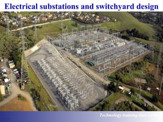
- 1. Electrical substations and switchyard design Technology training that works
- 2. Power network TS – Terminal substation ZS – Zone substation Technology www.idc-online.com/slideshare Technology TTrraaiinniinngg tthhaatt Wwoorrkkss
- 3. Substations • Terminal substations Zone substations Distribution substations • Terminal substations − High voltage transmission lines interconnected around the network at Terminal substations − Step down transmission voltage and supply power to zone substations. (Secondary transmission) − Secondary transmission voltages -132kV, 66kV and 33kV • Zone substations − Further step down voltage and supply to distribution networks − Typical output voltage - 6.6kV ~ 33kV • Distribution substations − Receive power from zone substations, supply power to distribution network and end users after stepping down voltage (MV or LV) Technology www.idc-online.com/slideshare Technology TTrraaiinniinngg tthhaatt Wwoorrkkss
- 4. Functions of a substation • Supply electric power to consumers continuously • Supply of electric power within specified voltage limits • Shortest possible fault duration • Optimum efficiency of electrical network • Supply of electrical energy to consumers at lowest cost Technology www.idc-online.com/slideshare Technology TTrraaiinniinngg tthhaatt Wwoorrkkss
- 5. Substation types Based on service • Transformer Substation – Transform power from one voltage to another voltage • Switching Substation – Switching of power lines without transforming voltages • Converting Substation – Conversion of AC - DC – AC (for HVDC transmission) Based on voltage • High voltage Substation - 11kV and 66kV • Extra high voltage Substation - 132kV and 400kV • Ultra high voltage Substation – Voltages above 400kV Based on installation • Outdoor Substation • Indoor Substation (Air insulated or gas insulated) − Usually for < 66kV − Heavily polluted areas − Adverse climatic conditions − Need for high reliability − Space constraints Technology www.idc-online.com/slideshare Technology TTrraaiinniinngg tthhaatt Wwoorrkkss
- 6. Air insulated substation vs Gas insulated substation Air insulated substation •Popular where space constraints and environmental restrictions are not severe •Exposed to environment •Not completely safe from electrical shock hazards Gas insulated substation •Limited space requirements •Protected from environment •Higher reliability than air insulated substation •Provides safety from electrical hazards – Shock, arc flash •More expensive than air insulated substation Technology www.idc-online.com/slideshare Technology TTrraaiinniinngg tthhaatt Wwoorrkkss
- 7. Substation types Outdoor Indoor – Air insulated Indoor – Gas insulated Technology www.idc-online.com/slideshare Technology TTrraaiinniinngg tthhaatt Wwoorrkkss
- 8. Location of key assets • Key assets refer to major electrical installations – Generating plants – Switching/Transformer substations – Transmission and distribution corridors • Correct location makes a substation optimal – In terms of investment – In terms of recurring losses – In terms of maintaining proper voltage profile – In terms of maintainability and expandability Technology www.idc-online.com/slideshare Technology TTrraaiinniinngg tthhaatt Wwoorrkkss
- 9. Planning criteria • Load forecast (average load, peak load, base load, etc.) • Security of supply (frequency and duration of outages) • Power quality (harmonics, voltage flickers, BIL, etc.) • Voltage limits (permissible voltage drop, etc.) • Site conditions (IP rating, soil resistivity, etc.) • System safety • System flexibility • System reliability • System earthing • System protection Technology www.idc-online.com/slideshare Technology TTrraaiinniinngg tthhaatt Wwoorrkkss
- 10. Principles of design General requirements Installation and equipment shall be capable of withstanding electrical, mechanical, climatic and environmental influences anticipated at site Design should take into account: • Purpose of the installation • End customer’s requirements such as power quality, reliability, availability • Ability to withstand effects of transient conditions – Switching large loads, short power outages and re-energisation • Safety of substation personnel and the public • Ease of extension (if required) and maintenance Technology www.idc-online.com/slideshare Technology TTrraaiinniinngg tthhaatt Wwoorrkkss
- 11. Approach to substation design • Collect field level data • Projection of future growth • Analyse data for optimised location of substation • Decide on basic system parameters • Decide substation configuration • Arrive at equipment ratings/sizing • Select appropriate equipment • Ensure maintainability • Ensure expandability Technology www.idc-online.com/slideshare Technology TTrraaiinniinngg tthhaatt Wwoorrkkss
- 12. Data collection • Make assumptions based on existing consumption patterns • Check for new developments • Assess new load requirements (E.g. A new industry being planned) • Check for any major demographic patterns in the offing • Assess seasonal change patterns • Assess possible growth of loads • Use economic indices for growth planning Technology www.idc-online.com/slideshare Technology TTrraaiinniinngg tthhaatt Wwoorrkkss
- 13. Data collection • Overall energy requirement and power demand – Indices from similar locations • List of connected loads and locations • Pattern of loading (variations due to requirements) – Loads of highly fluctuating nature to be considered separately • Assess load factor and diversity factor • Separate critical loads from non-critical • Assess future growth plans Technology www.idc-online.com/slideshare Technology TTrraaiinniinngg tthhaatt Wwoorrkkss
- 14. Projection of future growth • A difficult and uncertain exercise • Needs constant re-evaluation • Getting right inputs early • Provide additional capacity (say for a 5 year period) – Higher investment • Provide flexibility in the system for additions – Lower investment • Avoid the need for total equipment replacement to accommodate growth by proper initial planning Technology www.idc-online.com/slideshare Technology TTrraaiinniinngg tthhaatt Wwoorrkkss
- 15. Distribution voltage options for industries • Receiving and distribution at same voltage – Avoids need for transformer – Difficult to regulate voltage – Independent earthing of plant system not possible • Receiving at higher voltage – Involves transformer – Internal voltage independently variable through OLTC – Can choose system earthing independent of Utility – Transformer acts as buffer (harmonics, voltage dips) Technology www.idc-online.com/slideshare Technology TTrraaiinniinngg tthhaatt Wwoorrkkss
- 16. Single transformer, single bus configuration Technology www.idc-online.com/slideshare Technology TTrraaiinniinngg tthhaatt Wwoorrkkss
- 17. Industrial supply with duplicate feeds • Industries prefer duplication at different levels • High availability requirements • Expensive but flexible • Multiple bus sections with couplers • Duplicate bus systems • Duplication of feeders as well as transformers Technology www.idc-online.com/slideshare Technology TTrraaiinniinngg tthhaatt Wwoorrkkss
- 18. Dual incoming feeders with single transformer Technology www.idc-online.com/slideshare Technology TTrraaiinniinngg tthhaatt Wwoorrkkss
- 19. Substation components and equipment • Incoming transmission lines • Circuit breakers, disconnectors, earth switches • Power transformers • Busbars and cables • VTs and CTs • Lightning arrestors • Capacitor banks • Protection relay and control apparatus Technology www.idc-online.com/slideshare Technology TTrraaiinniinngg tthhaatt Wwoorrkkss
- 20. Loads and their characteristics • Utility – Dispersed loads – Mix of large and small loads • Residential (domestic) – Small, perhaps single phase – Daily and seasonal load cycle • Buildings (commercial/business premises) – Similar in nature to domestic but different daily cycle • Industrial – Larger loads concentrated in a small area – Load fluctuations and load generated problems Technology www.idc-online.com/slideshare Technology TTrraaiinniinngg tthhaatt Wwoorrkkss
- 21. Load forecasting • Should determine following factors: − Peak load − Average load − Connected load − Maximum demand − Load factor − Demand factor − Diversity factor • Critical load, essential loads, general purpose/non-critical loads • Constant voltage supply without sags or surges • Harmonic currents, need for filtering Technology www.idc-online.com/slideshare Technology TTrraaiinniinngg tthhaatt Wwoorrkkss
- 22. Basic system parameters • Voltage level selection – Optimised cost/performance – Availability (incoming supply) – Standardisation • Fault level – Present – Future system growth • Nature of loads – Critical loads – Tolerance for interruptions – Harmonics, power factor – Steady, cyclic loads Technology www.idc-online.com/slideshare Technology TTrraaiinniinngg tthhaatt Wwoorrkkss
- 23. Configuration • Incomers and outgoing – Number of incomers – Incoming and outgoing voltage levels • Redundancy planning – Type of distribution (Radial, Ring etc.) – Type of redundancy (Additional equipment, spare capacity etc) – Integration of local generation if any (wind power, solar, co-generation) • System Earthing – Local statutory requirements • Equipment for voltage/power factor/harmonic control Technology www.idc-online.com/slideshare Technology TTrraaiinniinngg tthhaatt Wwoorrkkss
- 24. Design criteria • Ensures all parties involved in design understand and agree with rules and basic needs • Ensures client and designer have considered all basic aspects of project’s features • Ensures client accepts operational and maintenance needs • Differentiates between requirements of specific project and generalized requirements of standard specifications Technology www.idc-online.com/slideshare Technology TTrraaiinniinngg tthhaatt Wwoorrkkss
- 25. System reliability • Primarily relates to equipment outages and customer interruptions • In normal operating conditions, all equipment (except standby equipment) are energized and all customers receive power • Scheduled outages (such as maintenance) and unscheduled events disrupt normal operating conditions and can lead to outages, interruptions • Substation design plays important role in reliability of the System Technology www.idc-online.com/slideshare Technology TTrraaiinniinngg tthhaatt Wwoorrkkss
- 26. System flexibility • Proper busbar configurations, connections - Loads can be added and/or changed with ease • Spare feeders even if breakers are not furnished • Spare space for future transformer bays, incoming feeders if substation is subject to significant load rise in future • Enough ampacity and short circuit capability for conductors for prospective load increases in future • Adequate capacity for transformers so they are not overloaded during future expansion projects Technology www.idc-online.com/slideshare Technology TTrraaiinniinngg tthhaatt Wwoorrkkss
- 27. Substation layout • Consists arrangement of number of switchgear in orderly fashion – Based on function and separation space • Earth clearance: Clearance between live parts and earthed structures • Phase clearance: Clearance between live parts of different phases • Isolating distance: Clearance between contacts of isolator • Section clearance: Clearance between live parts and terminals of a work section • Should provide security of supply - Very important • Redundancy to ensure reliability in the event of fault, equipment breakdown or maintenance • However, not always practically feasible due to very high cost of implementation Technology www.idc-online.com/slideshare Technology TTrraaiinniinngg tthhaatt Wwoorrkkss
- 28. Security of supply Types of substations giving varying securities of supply: • Type 1: No outage required within substation for either maintenance, fault conditions • Type 2: Short outage necessary to transfer load to an alternative circuit for maintenance/ fault conditions • Type 3: Loss of circuit/ section of substation due to fault, maintenance • Type 4: Loss of entire substation due to fault, maintenance Technology www.idc-online.com/slideshare Technology TTrraaiinniinngg tthhaatt Wwoorrkkss
- 29. Single Busbar configuration Advantages •Individual bus sections can either be connected together or separated based on need •Comparatively simple construction •Comparatively smaller space requirements •Comparatively lower costs Drawbacks •Failure of one bus section would result in failure of power to that section •Comparatively lesser flexibility when compared with configurations discussed in coming slides Technology www.idc-online.com/slideshare Technology TTrraaiinniinngg tthhaatt Wwoorrkkss
- 30. Double busbar configuration Advantages •Improved reliability of power supply •Much more flexibility than single bus bar scheme Drawbacks •More complex system •More space requirements •More complex protection requirements •Higher costs Technology www.idc-online.com/slideshare Technology TTrraaiinniinngg tthhaatt Wwoorrkkss
- 31. Breaker and a half configuration • Utilises legs with three breakers connected between two buses • Two breakers connected in each leg – One and half breaker per circuit • All breakers are closed and both main buses energised under normal conditions • Two associated breakers must be opened to trip a circuit • High reliability, maintainability and flexibility • Protective relaying more complex compared with earlier discussed schemes • Breakers and other components must be rated for sum of load of two circuits • High security against loss of supply • More complex • More space requirements • More expensive than other configurations Technology www.idc-online.com/slideshare Technology TTrraaiinniinngg tthhaatt Wwoorrkkss
- 32. Mesh type configuration Advantages •Improved reliability of power supply •Increased flexibility of operation •More easier maintenance of switchgear without disrupting supply Drawbacks •More complex than schemes mentioned earlier •More complex protection systems •More space requirements •More costlier than previous schemes Technology www.idc-online.com/slideshare Technology TTrraaiinniinngg tthhaatt Wwoorrkkss
- 33. DO YOU WANT TO KNOW MORE? If you are interested in further training or information, please visit: http://idc-online.com/slideshare Technology www.idc-online.com/slideshare Technology TTrraaiinniinngg tthhaatt Wwoorrkkss