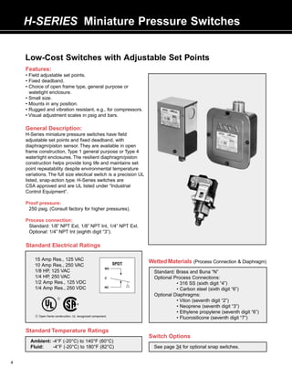
1. H-SERIES Miniature Pressure Switches
Low-Cost Switches with Adjustable Set Points
Features:
• Field adjustable set points.
• Fixed deadband.
• Choice of open frame type, general purpose or
watetight enclosure.
• Small size.
• Mounts in any position.
• Rugged and vibration resistant, e.g., for compressors.
• Visual adjustment scales in psig and bars.
General Description:
H-Series miniature pressure switches have field
adjustable set points and fixed deadband, with
diaphragm/piston sensor. They are available in open
frame construction, Type 1 general purpose or Type 4
watertight enclosures. The resilient diaphragm/piston
construction helps provide long life and maintains set
point repeatability despite environmental temperature
variations. The full size electical switch is a precision UL
listed, snap-action type. H-Series switches are
CSA approved and are UL listed under “Industrial
Control Equipment”.
Proof pressure:
250 psig. (Consult factory for higher pressures).
Process connection:
Standard: 1/8” NPT Ext, 1/8” NPT Int, 1/4” NPT Ext.
Optional: 1/4” NPT Int (eighth digit “3”).
Standard Electrical Ratings
15 Amp Res., 125 VAC Wetted Materials (Process Connection & Diaphragm)
10 Amp Res., 250 VAC SPDT
NO
1/8 HP, 125 VAC Standard: Brass and Buna “N”
1/4 HP, 250 VAC C Optional Process Connections:
1/2 Amp Res., 125 VDC • 316 SS (sixth digit “4”)
1/4 Amp Res., 250 VDC NC
• Carbon steel (sixth digit “6”)
Optional Diaphragms:
^ %
1
• Viton (seventh digit “2”)
• Neoprene (seventh digit “3”)
• Ethylene propylene (seventh digit “6”)
1 Open frame construction, UL recognized component.
• Fluorosilicone (seventh digit “7”)
Standard Temperature Ratings
Switch Options
Ambient: -4°F (-20°C) to 140°F (60°C)
Fluid: -4°F (-20°C) to 180°F (82°C) See page 34 for optional snap switches.
4
2. 4 123
Select H-Series pressure switch below
How to Select and Order SPDT (Form “C” Contact), Brass and Buna “N”
ASCO H-Series switches are a single Fixed 1/8” NPT 1/4” NPT 1/8” NPT
Adjustable Deadband External Process External Process Internal Process
switch and transducer assembly. Operating At Connection Connection Connection 2
Range Mid-Range
How to Select (psig) (psig) 1 Catalog No. Catalog No. Catalog No.
1. Select type of switch (open frame,
general purpose or watertight)..
Open frame construction
2. Select the adjustable operating range 4 - 12 1.6 HB46A218 HB46A214 HB46A215
based on the desired actuation pressure. 8 - 25 1.8 HB36A218 HB36A214 HB36A215
3. Select desired process connection. 20 - 50 2.4 HB26A218 HB26A214 HB26A215
35 - 80 3.5 HB16A218 HB16A214 HB16A215
How to Order 40 - 120 7.0 HC26A218 HC26A214 HC26A215
Simply order the selected H-Series pressure 80 - 200 10.0 HC16A218 HC16A214 HC16A215
switch by catalog number, e.g., HB46A218
describes an open frame pressure switch
Type 1 - General purpose enclosure
with adjustable operating range of 4 to 12 4 - 12 1.6 HB40A218 HB40A214 HB40A215
psig, 1/8” NPT external brass process 8 - 25 1.8 HB30A218 HB30A214 HB30A215
connection and Buna “N” diaphragm. 20 - 50 2.4 HB20A218 HB20A214 HB20A215
35 - 80 3.5 HB10A218 HB10A214 HB10A215
Options 40 - 120 7.0 HC20A218 HC20A214 HC20A215
Add appropriate suffix or change appropriate 80 - 200 10.0 HC10A218 HC10A214 HC10A215
digit in catalog number for desired option, e.g.,
Type 4 - Watertight enclosure
HB46A2 2 8 P describes an open frame pres-
sure switch with optional viton diaphragm 4 - 12 1.6 HB41A218 HB41A214 HB41A215
(seventh digit “2”) and gold contact snap 8 - 25 1.8 HB31A218 HB31A214 HB31A215
switch (suffix “P”). 20 - 50 2.4 HB21A218 HB21A214 HB21A215
35 - 80 3.5 HB11A218 HB11A214 HB11A215
40 - 120 7.0 HC21A218 HC21A214 HC21A215
80 - 200 10.0 HC11A218 HC11A214 HC11A215
1 Values shown are nominal. 2 May be used for panel or bracket mounting.
Dimensions (inches)
H-Series Pressure
General Purpose Enclosure
2.2 2.8
Open Frame Watertight Enclosure
1.7
2.1 2.5 4.0
.8 1.0 1/2NPT
7/8
KNOCKOUT
BOTH
5.0 SIDES
5.2
3.5
.9 1/8 NPT INTERNAL 1.0
1/8 NPT INTERNAL 1/8 NPT EXTERNAL OR 1/8 NPT INTERNAL
1/4 EXTERNAL
5
3. H-SERIES Miniature Pressure Switches
Suffix S: Low-Cost Switches with
Adjustable Set Points and Adjustable Deadband
Features:
• Field adjustable set points.
• Limited adjustable deadband.
• Choice of open frame type, general
purpose or watetight enclosure.
• Small size.
• Mounts in any position.
• Rugged and vibration resistant,
e.g., for compressors.
• Visual adjustment scales in psig
and bars.
Standard Ratings and
Wetted Materials
(See page 4)
Dimensions
(See page 5)
How to Select and Order
ASCO H-Series Suffix S switches are a Select H-Series Suffix S switch below
single switch and transducer assembly. SPDT (Form “C” Contact), Brass and Buna “N”
Adjustable
Deadband 1/8” NPT 1/4” NPT 1/8” NPT
How to Select
Adjustable At External Process External Process Internal Process
1. Select type of switch enclosure (open
Operating Mid-Range Connection Connection Connection 2
frame, general purpose or watertight). Range (psig) 1
2. Select the adjustable operating range (psig) From/To Catalog No. Catalog No. Catalog No.
based on the desired actuation pressure and
desired deadband (reactuation) pressure. Open frame construction
3. Select desired process connection. 4 - 12 1.5 - 3.5 HB46A218S HB46A214S HB46A215S
8 - 25 2 - 4 HB36A218S HB36A214S HB36A215S
How to Order
20 - 50 3 - 5 HB26A218S HB26A214S HB26A215S
Simply order the selected H-Series Suffix S
35 - 80 6 - 8 HB16A218S HB16A214S HB16A215S
pressure switch by catalog number,
40 - 120 8 - 13 HC26A218S HC26A214S HC26A215S
e.g., HB46A218S describes an open frame
80 - 200 15 - 20 HC16A218S HC16A214S HC16A215S
H-Series Suffix S pressure switch with
adjustable operating range of 4 to 12 psig Type 1 - General purpose enclosure
and adjustable deadband at mid-range of 1.5 4 - 12 1.5 - 3.5 HB40A218S HB40A214S HB40A215S
to 3.5 psig, 1/8” NPT external brass process 8 - 25 2 - 4 HB30A218S HB30A214S HB30A215S
connection and Buna “N” diaphragm. 20 - 50 3 - 5 HB20A218S HB20A214S HB20A215S
35 - 80 6 - 8 HB10A218S HB10A214S HB10A215S
Options (See page 4) 40 - 120 8 - 13 HC20A218S HC20A214S HC20A215S
Change appropriate digit in catalog number 80 - 200 15 - 20 HC10A218S HC10A214S HC10A215S
for desired option, e.g., HB46A2 2 8S
describes an open frame pressure switch Type 4 - Watertight enclosure
with adjustable operating range and deadband 4 - 12 1.5 - 3.5 HB41A218S HB41A214S HB41A215S
with optional viton diaphragm (seventh digit “2”). 8 - 25 2 - 4 HB31A218S HB31A214S HB31A215S
20 - 50 3 - 5 HB21A218S HB21A214S HB21A215S
35 - 80 6 - 8 HB11A218S HB11A214S HB11A215S
40 - 120 8 - 13 HC21A218S HC21A214S HC21A215S
80 - 200 15 - 20 HC11A218S HC11A214S HC11A215S
1 Values shown are nominal. 2 May be used for panel or bracket mounting.
6
4. 4 123
Suffix L: Lowest-Cost Switches with
Adjustable Set Points (Open Frame Construction)
Features:
• Low cost for OEM applications.
• Miniature size.
• Wide selection of adjustable ranges.
• Fixed deadband.
• Resilient diaphragm/piston sensor
for long life.
• Precision single-pole, double-throw
snap switch with quick-connect 1/4”
spade terminals.
Standard Ratings and
Wetted Materials
(See page 4)
Dimensions (inches)
How to Select and Order
ASCO H-Series Suffix L switches are a 1.2 2.2
single switch and transducer assembly.
How to Select
1. Select the adjustable operating range
based on the desired actuation pressure.
2. Select desired process connection. 3.4
How to Order
Simply order the selected H-Series Suffix L
pressure switch by catalog number,
e.g., HB46A218L describes an open frame
pressure switch with adjustable operating
range of 4 to 12 psig, 1/8” NPT external brass
process connection and Buna “N” diaphragm.
Options (See page 4)
Change appropriate digit in catalog number Select H-Series Suffix L switch below
for desired option, e.g., HB46A2 2 8L
SPDT (Form “C” Contact), Brass and Buna “N”
describes an open frame pressure switch
with adjustable operating range and optional Fixed 1/8” NPT 1/4” NPT 1/8” NPT
viton diaphragm (seventh digit “2”). Adjustable Deadband External Process External Process Internal Process
Note: Optional snap switches not available Operating At Connection Connection Connection 2
on suffix “L” units. Range Mid-Range
(psig) (psig) 1 Catalog No. Catalog No. Catalog No.
4 - 12 3.0 HB46A218L HB46A214L HB46A215L
8 - 25 3.6 HB36A218L HB36A214L HB36A215L
20 - 50 5.5 HB26A218L HB26A214L HB26A215L
35 - 80 7.0 HB16A218L HB16A214L HB16A215L
40 - 120 14.0 HC26A218L HC26A214L HC26A215L
80 - 200 21.0 HC16A218L HC16A214L HC16A215L
1 Values shown are nominal. 2 May be used for panel or bracket mounting.
7
5. OPTIONS Pressure/Temperature Switches
H-Series, P-Series and S-Series P-Series
Snap-Action Switch Options Switch Options
Optional snap-action switches to meet specific electrical loads Panel Mount – Open frame P-Series compact switch units are
or application conditions are available on most ASCO TRI-POINT available for panel mounting with the switch unit inside and the
switch units. Generally, the construction of a switch unit with transducer outside. The panel separates the fluid sensing portion
optional snap-action switches contains other specific parts and from the electromechanical portion. Five holes for bolts and
may be ordered only as a factory-built unit. To specify a particular operating stem must be drilled or punched through the panel.
optional construction, add the appropriate suffix to the switch unit Three constructions are available: add the suffix listed below to
catalog number, e.g., SA10D with optional gold contact snap- the switch unit catalog number for the desired thickness.
action switch (suffix “P”) would become SA10D P .
Catalog Deadband Variation Panel Thickness Suffix
Description Electrical Rating Suffix From Listing
10 Ga (.135+.005) 10
5 Amp, 125, 250 VAC 14 Ga (.075+.005) 11
DC Rating 1/4 HP, 125 VAC SA: +50% 16 Ga (.060+.005) 12
1 Amp 1/2 HP, 250 VAC G SB, SC, PA: +100%
Double Break 1 Amp, 125 VDC H: +200%
1/2 Amp, 250 VDC PB: +400%
SA: +50%
DC Rating 10 Amp, 125 VAC, VDC M SB, SC, PA: +100%
10 Amps, SPDT 1/8 HP, 125 VAC, VDC H: +120%
PB: +400%
Double-pole 5 Amp, 125, 250 VAC
Double-throw 1/8 HP, 125 VAC S-Series
(Two SPDT 1/4 HP, 250 VAC K SA, SB, SD, SE, PB: +50% Switch Options
Switches with 1/2 Amp, 125 VDC Industrial Adjusting Nut Covers –
Common Lever) 1/4 Amp, 250 VDC Available in clear plastic or metal to
Gold Contact 1 Amp, 28 VAC SA, SB, SC, PA: +25% prevent tampering with set point
Dry Circuit SPDT 1 Amp, 28 VDC P H: +50% adjusting nuts.
25 Amp Res, 28 VDC PB, PC: +100% Clear plastic cover: To order, add
Hermetically 10 Amp Ind, 28 VDC SA, PA: +100% suffix “1” to the switch unit catalog
Sealed 5 Amp Motor, 28 VDC H H: +200% number, or order separately as SP01.
SPDT 3 Amp Lamp, 28 VDC PB: +600% Metal cover: To order, add suffix “2” to
the switch unit catalog number, or
1 Amp, 125 VAC
order separately as SP02.
5 Amp, 125, 250 VAC JIC Construction – A switch unit
High Ambient 1/8 HP, 125 VAC having the electrical and adjusting nut
250°F 1/4 HP, 250 VAC F SA, SB, SC: +25% covers attached to the switch body by
SPDT 1/2 Amp, 125 VDC a chain. Also designed to Type 13
1/4 Amp, 250 VDC specifications. To order, add suffix “3”
20 Amp, 125, 250 VAC to the switch unit catalog number, or
High Power 1 HP, 125 VAC SA: +50% order separately as SP03.
1 HP 2 HP, 250 VAC W SB, SC: +100% Terminal Block – Applicable to switch
SPDT 1/2 Amp, 125 VDC PB: +400% units with one single-poledouble-throw
switch. The terminal strip is prewired
1/4 Amp, 250 VDC
to the snap-action switch. To order, add
Moisture 5 Amp, 125, 250 VAC
suffix “4” to the switch unit catalog
Resistant 1/8 HP, 125 VAC SA: None number, or order separately as SP04.
Sealed Switch 1/4 HP, 250 VAC J SB, SC, PA: +25% Factory Sealed – Explosion-proof
SPDT 1/2 Amp, 125 VDC PB, H: +50% units may be ordered with a factory
1/4 Amp, 250 VDC seal separating the electrical chamber
Tight 5 Amp, 125, 250 VAC from the conduit hubs and 24” long
Fixed 1/8 HP, 125 VAC #14 AWG 105°C. rated lead wires. To
Deadband 1/4 HP, 250 VAC T SB, SC: -50% order, change the fourth digit of the
SPDT 1/2 Amp, 125 VDC switch unit catalog number from “2” to
“3”, e.g., SA1 2 D becomes SA1 3 D.
34
6. Definitions and Fluid Compatibility Guide
Definitions
Accuracy – The maximum deviation from the set point Switch Unit – ASCO uses the term “switch unit” to describe
under specified operating condition (ambient temperature, the electromechanical portion of a pressure or temperature
barometric pressure, etc.). switch. This is used in conjunction with a transducer unit to
form a complete pressure or temperature switch.
Adjustable Deadband – Refers to the capability of a
pressure or temperature switch to allow the deadband to be Transducer Unit – ASCO uses the term “transducer unit” to
adjusted over a given range. Certain ASCO TRI-POINT describe that portion of a pressure or temperature switch to
switches have an adjustable deadband which can be which a pressure or temperature is applied which converts
adjusted over the total operating range of the switch. the input signal to another form of energy to operate the
switch unit.
Adjustable Operating Range – The pressure or tempera-
ture range of the switch within which the set point may be Two-Stage (Dual) – ASCO uses the term “two stage” to
adjusted. describe a pressure or temperature switch which is equivalent
to two pressure or temperature switches which are
Differential Pressure – The difference between two independently adjustable. This switch is equivalent to two
pressures. A differential pressure switch senses two pressure fixed deadband switches.
sources and can be adjusted to actuate on a desired
difference between them. Deadbands – The deadband is the difference between the
set point and reset point readings. Deadbands are listed
Guage Pressure – The actual reading of a typical pressure in the specification tables at nominal values. They are
guage and is the difference between the pressure within a representative of the deadbands of the units at the middle
vessel and the atmospheric pressure surrounding it. It is of the range.
normally measured in pounds per square inch (psig).
The deadband values for the full range adjustable deadband
Manual Reset – The switch is a semi-automatic device switches and limited adjustable deadband switches indicate
which operates automatically with a signal change in one the values through which the deadband may be adjusted.
direction but must be manually reset once the signal returns
to its original position. Generally, as the set point is adjusted through the operating
range, the deadband will vary. Normally, it will become
Proof Pressure – A pressure which a device can be narrower as the set point is towards the bottom of the range,
subjected to for extended periods of time without changes and will become wider when the set point is towards the top
in its operating characteristics. of the range. The graph shown below indicates representative
trends of this type of deadband variation.
Rated Overrange Temperature – A temperature which a
device can be subjected to for extended periods of time
without changes in its operating characteristics. Deadbands
Repeatability – The closeness of agreement among a 1.5 x Catalog
number of consecutive measurements of the output for the Value
same value of input under the same operating conditions
approaching from the same direction. Repeatability is Catalog
normally specified as a percentage of the upper limit of the Value
operating range.
Half Catalog
Example: Operating range 5-100 psig with +1% Value
repeatability; equals +1% of 100 psig or +1 psig.
Bottom Mid Top
Reset Point – After a pressure or temperature switch has
Position of Set Point in Range
reached its set point and operated the electrical switch, it
must return to a point called the reset point before the Temperature switch deadbands are a result of the characteris-
electrical switch can return to its original position. tics of the vapor pressure curve as well as other factors.
Normally, this results in a deadband which is narrower in the
Set Point – The pressure reading at which the electrical top third of the range than in the bottom third of the range.
switch element changes contact position (it can be specified The values published are nominal and representative of mid-
either increasing or decreasing). range set points.
36
7. 4 123
Fluid Compatibility Guide
These recommendations are to be used as a guide only, as service Transducer Material Code of Two Digits represents process connection
life of material is dependent on temperature, concentrations, or material and diaphragm material, respectively; these are the sixth and
catalysts that may be added and other conditions which are seventh positions of the pressure transducer catalog number.
beyond our control.
Consult ASCO for specific service applications. Process Connection: 6th Position Diaphragm: 7th Position
Note: Items in black circles are standard catalog units. 1 Aluminum 4 316 S.S. 1 Buna “N” 4 316 S.S.
All others available on factory order. 2 Brass 7 Nylon/Brass 2 Viton 6 Ethylene Propylene
P - Indicates preferred construction. S - Indicates satisfactory construction. 3 303 S.S. 3 Neoprene 7 Fluorosilicone
Material Code 11 12 13 16 17 21 22 23 26 27 31 32 33 36 37 42 44 71
Available
Vacuum Yes Yes Yes Yes Yes Yes Yes Yes Yes Yes Yes Yes Yes Yes Yes Yes No No
Ranges
Inches of Water Yes Yes Yes Yes Yes No No No No No Yes Yes Yes Yes Yes Yes No No
P.S.I.G. 5 to 400 400 400 400 400 3500 3500 3500 3500 3500 8000 8000 8000 8000 8000 8000 400 200
Acetic Acid S S P
Acetylene P S S S S S S S
Air P S S S S S S S S S S S S S S S S P
Ammonia P
Argon-Welding 1 P S S S S S S S S S S S S S S S S P
Benzene-Benzol P S S S S
Butane P S S S S S S S
Carbon Tetrachloride P P S
Cellulube P S S S S S S S
Coke Oven Gas P P S
Ethyl Alcohol (denatured) P S S S S S S S S S S S S S S S S
Ethylene Glycol P S S S S S S S S S S S S S
Freon Refrigerants P
Freon Solvents
P S S S S S
(“MF”, “TF”, “BF”)
Fuel Oils and Diesel 4 P S S S S S S S
Gasoline P
Gas, Inert P S S S S S S S S S S S S S S S S P
Gas (natural and
P S S S S S S S S S S S S S
manufactured) 4
Helium P S S S S S S S S S S S S S S S S P
Hydrogen P S S S S S S S S S S S S S
Jet Fuel (JP1 to JP6) P S S S S S S S
Kerosene P S S S S S S
Methyl Alcohol (Methanol) P S S S S S S S S S S S S S
Naphtha P S S S S S S S
Nitrogen P S S S S S S S S S S S S S S S S P
Oils (coolant, hydraulic,
P S S S S S S S P
lubricating and motor)
Oxygen, Gaseous 2 S P S S S S S S S S S
Potassium Sulfate P S S S S S S S S S S S S S S S S
Propane Gas and Liquid P S S S S S S S S S S
“Pydraul” (“Monsanto”) P S S S S S S S
Steam 3 P S S S S S S S S S
Steam Condensate P S S S S S S S S S P
Stoddard Solvent P S S S S S S S
Toluene (Tolulo) P S S S S
Vacuum P S S S S S S S S S S S S S S S
Vegetable Oil P S S S S S S S S S
Vinegar S S S S P
Water, Fresh, Boiler Feed P S S S S S S S S S P
Water (Distilled, Deionized,
P S S S S S S
Demineralized)
Water, Sea S
Notes: 1 For high purity applications use stainless steel transducers. 2 Oxygen service requires special cleaning, specify suffix “H”. 3 For steam service a condensate loop (pigtail) is required.
4 For pressure transducers for combustion service see pages 20-23. 5 Material availability refers to standard gauge pressure constructions only.
37