Weitere ähnliche Inhalte Ähnlich wie Mercedes benz w208 clk 320 wis contents (20) Kürzlich hochgeladen (20) 1. MERCEDES‐BENZ W208 CLK 320 WIS CONTENTS
1) REMOVING AND INSTALLING PUSHBUTTON CONTROL MODULE
2) REMOVING AND INSTALLING AIRBAG ON STEERING WHEEL
3) REMOVING AND INSTALLING PASSENGER AIRBAG UNIT
4) INSTALL LEFT FRONT OR RIGHT RPM SENSOR
5) FUNCTION OF WHEEL SPEED SENSOR
6) REMOVING AND INSTALLING ACTIVATED CHARCOAL CANISTER
7) INSTALL LEFT OR RIGHT REAR AXLE SPEED SENSOR
8) ESP HYDRAULIC UNIT
9) INSTALL TRANSMISSION WITH TORQUE CONVERTER
10) REMOVING AND INSTALLING BAS DIAPHRAGM TRAVEL SENSOR
11) BLEED BRAKE SYSTEM
12) REMOVING, CHECKING AND INSTALLING REAR AXLE BRAKE PADS
13) INSTALL FRONT AXLE BRAKE PADS
14) INSTALL BRAKE DISC
15) ADJUST PARKING BRAKE
16) INSTALL CAMSHAFTS
17) INSTALL CRANKSHAFT
18) INSTALL RADIATOR
19) REMOVE, INSTALL POLY V‐BELT
20) INSTALL CYLINDER HEAD COVER
21) VIBRATION DAMPER
22) DRIVE PLATE
23) INSTALL INJECTION VALVES (ME‐SFI)
24) INSTALL INTAKE MANIFOLD
25) INSTALL GENERATOR POLY‐V BELT PULLEY
26) INSTALL EXHAUST MANIFOLD
27) INSTALL EXHAUST GAS RECIRCULATION VALVE
28) REMOVE, INSTALL AIR PUMP
29) REPLACE SPARK PLUGS
30) INSTALL KNOCK SENSORS
31) INSTALL CRANKSHAFT POSITION SENSOR
32) INSTALL IGNITION COILS
33) REMOVE STARTER, INSTALL
34) INSTALL ENGINE MOUNT
35) INSTALL ALTERNATOR
36) ENGINE OIL AND FILTER CHANGE
37) INSTALL COOLANT PUMP
38) INSTALL COOLANT THERMOSTAT
39) INSTALL ACCELERATOR PEDAL
40) REMOVING AND INSTALLING TORSION BAR ON FRONT AXLE
41) INSTALL REAR SPRING
42) REMOVING AND INSTALLING FRONT SPRING
43) INSTALL REAR SUSPENSION STRUT
44) INSTALL FRONT SHOCK ABSORBER
45) INSTALL REAR SHOCK ABSORBER
46) INSTALL COMPLETE REAR AXLE
47) INSTALL PROPELLER SHAFT
48) REMOVAL AND INSTALLATION OF PROPELLER SHAFT INTERMEDIATE BEARING AND REPLACEMENT OF
GROOVED BALL BEARING
1
2. 49) REPLACE BRAKE FLUID
50) CARRYING OUT BLEEDING OPERATION
51) REMOVING AND INSTALLING BRAKE BOOSTER
52) REMOVING AND INSTALLING MECHANICAL STOP LAMP SWITCH
53) SPECIFIED GEAR OILS (CARS, CROSS‐COUNTRY VEHICLES) ‐ SURVEY
54) DISMANTLING AND ASSEMBLING RIGID JACKET TUBE
55) REMOVING AND INSTALLING ELECTRONIC STEERING LOCK
56) STARTER SWITCH (EZS
57) REMOVING AND INSTALLING CONTACT SPIRAL
58) REMOVING AND INSTALLING JACKET TUBE
59) CHECKING OIL PRESSURE OF POWER STEERING PUMP
60) FILL POWER STEERING PUMP AND BLEED
61) INSTALL POWER STEERING PUMP
62) INSTALL STEERING IDLER ARM, REPLACING BEARING BUSH
63) INSTALL TIE ROD BALL JOINT
64) REPLACE FUEL FILTER
65) REMOVING AND INSTALLING EXPANSION RESERVOIR
66) DRAINING AND FILLING FUEL TANK
67) REMOVE, INSTALL FUEL GAGE SENSOR
68) INSTALL FUEL TANK
69) REMOVING, INSTALLING FUEL PUMP
70) REMOVING, INSTALLING SHUTOFF VALVE
71) REMOVING AND INSTALLING EXHAUST SYSTEM COMPLETE
72) INSTALL THE OXYGEN SENSOR
73) REMOVING AND INSTALLING CATALYTIC CONVERTER OR FRONT EXHAUST SYSTEM
74) REMOVING AND INSTALLING BATTERY
75) STAMPING IN VEHICLE IDENTIFICATION NUMBER
76) VEHICLE IDENTIFICATION NUMBER
77) INSTALL FRONT AXLE HALF
78) INSTALL DRAG LINK
79) REMOVING AND INSTALLING FRONT SEATS
80) INSTALL FRONT DOOR
81) REMOVING AND INSTALLING INSTRUMENT PANEL
82) REMOVING AND INSTALLING ENGINE HOOD
83) INSTALL FRONT FENDERS
84) INSTALL WINDSHIELD
85) REMOVING AND INSTALLING FRONT BUMPER
86) REMOVING AND INSTALLING COVER BELOW INSTRUMENT PANEL (LEFT)
87) REMOVING AND INSTALLING CENTER CONSOLE
88) ADJUST FRONT DOOR
89) STARTER SWITCH CONTROL MODULE
90) INSTALL BULBS OF HEADLAMP UNIT
91) REMOVING AND INSTALLING TELESCOPING NOZZLE FOR HEADLAMP CLEANING SYSTEM
92) REMOVING AND INSTALLING HEADLAMP CLEANING SYSTEM WASHING WATER RESERVOIR
93) REMOVING AND INSTALLING OVERHEAD CONTROL PANEL CONTROL MODULE
94) INSTALL RAIN SENSOR
95) REMOVING, DISASSEMBLING AND INSTALLING REAR SHELF
96) VENTILATION
97) REMOVING AND INSTALLING BLOWER MOTOR
2
3. AR83.40-P-6350C Removing and installing pushbutton control module 23.9.96
MODEL 129 as of 1.6.96,
140, 202 as of 1.9.95,
208, 210 with CODE (581a) Air conditioning (automatic)
P83.40-0386-09
Shown on model 129 2 Connector
3 Connector
1 Removal tools N22 Pushbutton control module
e d Removal, installation
1 Pull out A/C pushbutton control module iFor this purpose insert removal
(N22) tools (1)
Press back retaining springs (arrow) on
removed pushbutton control module and pull
out removal tools (1)
2 Disconnect connectors (2, 3) on A/C iUnhook connectors by pivoting retaining
pushbutton control module (N22) strap
3 Reinstall in opposite order i Installation
When replacing automatic A/C pushbutton
control module on models 140, 202, 208,
210, version coding must be carried out.
Page 1 of 1© Daimler AG, 8/1/15, G/04/14, ar83.40-p-6350c, Removing and installing pushbutton control module
MODEL 129 as of 1.6.96, 140, 202 as of 1.9.95, 208, 210 with CODE (581a) Air conditioning (automatic)
3
4. AR91.60-P-0660G Removing and installing airbag on steering wheel 4.2.10
MODEL 170, 208
Illustrated on model 170
P91.60-0407-06
e d Removal, installation
a Injury hazard when testing or repairing Store airbags with opening surface pointing AS91.00-Z-0001-01ADanger!
airbags or emergency tensioning retractors up, do not expose to temperatures above
100 °C. Interrupt electric circuit when
working on these units
p Important instructions for performing repair, Model 129 as of 1.7.93, 163, 168, 170, 202 as AH91.00-P-0002-01B
body work and welding on vehicles with of 1.7.93, 208, 210, 463, 638, 901, 902, 903,
airbags and emergency tensioning retractors 904
p Evaluation of airbags and emergency Model 129 as of 1.7.93, 163, 168, 170, 202 as AH91.00-P-0006-01B
tensioning retractors on accident vehicles of 1.7.93, 208, 210, 463, 638, 901, 902, 903,
904
i Legal regulations on handling and storing Models 124, 129, 140, 163, 168, 170, 202, 208,AH91.00-P-0004-01A
airbags and emergency tensioning retractors 210,314, 316, 318, 463, 638, 901, 902, 903,
904, 950, 952, 953, 954
o Instructions on disposal of airbags and All models OS91.00-P-0001-01A
emergency tensioning retractors
1 Disconnect ground lead from battery
2 Unscrew two screws (arrow) n *BA91.60-P-1001-01A
iHold airbag while unscrewing
l *126589001000
3 Remove airbag from steering wheel and
disconnect connector from squib on gas
generator
4 Disconnect horn contacts
Rendering airbags unusable AR91.60-P-0611A
5 Install in opposite order iAfter the driver's airbag has triggered it is
always necessary to replace the steering
wheel
6 Check combination switch automatic return
7 Perform diagnosis AD91.60-P-6000A
nAirbag
Number Designation Model 170 Model 208
Screw for airbag on steering wheel Nm 8 8BA91.60-P-1001-01A
Page 1 of 2© Daimler AG, 8/1/15, G/04/14, ar91.60-p-0660g, Removing and installing airbag on steering wheel
MODEL 170, 208
4
5. 126 589 00 10 00
Screwdriver attachment
Page 2 of 2© Daimler AG, 8/1/15, G/04/14, ar91.60-p-0660g, Removing and installing airbag on steering wheel
MODEL 170, 208
5
6. AR91.60-P-0680K Removing and installing passenger airbag unit 5.12.96
MODEL 208
1 Bolt
R12/8 Initiator for front passenger airbag
(AB)
P91.60-0513-04
e d Remove/install
a Risk of injuryDanger! when carrying out test or Store airbag unit with expulsion area on top, AS91.00-Z-0001-01A
repair work on airbag or emergency do not subject to temperatures above 100
tensioning retractor units °C. Interrupt power supply when working on
such units.
p Important instructions for performing repair, Models 129 as of 1.7.93, 163, 168, 170, 202 AH91.00-P-0002-01B
body work and welding on vehicles with as of 1.7.93, 208, 210, 463, 638, 901, 902,
airbags and emergency tensioning retractor 903, 904
units
i Legal regulations concerning the handling Models 124, 129, 140, 163, 168, 170, 202, 208,AH91.00-P-0004-01A
and storage of airbag and emergency 210, 314, 316, 318, 463, 638, 901, 902, 903,
tensioning retractors 904, 950, 952, 953, 954
o Notes on disposal of airbag and emergency All models OS91.00-P-0001-01A
tensioning retractors
1 Disconnect ground cable of battery AR54.10-P-0003A
2 Remove instrument panel AR68.10-P-1000K
3 Disconnect connector from the initiator i Installation: Connector must audibly
(R12/8) at the inflator latch into position
4 Unscrew nut (2) for front passenger airbag
unit
5 Remove front passenger airbag unit
6 Make airbag units unusable AR91.60-P-0611A
7 Install in the reverse order
8 Carry out diagnosis.
a AD91.60-P-6000A
Page 1 of 1© Daimler AG, 8/1/15, G/04/14, ar91.60-p-0680k, Removing and installing passenger airbag unit
MODEL 208
6
7. AR42.30-P-0712A Remove/install left front or right rpm sensor 8.12.11
MODEL 129, 140, 170, 202, 203, 208, 210
P42.30-0238-06
Modification notes
29.11.11 Long-life grease repair materials replaced by hot-grease
paste
Fig. item etc. Work instructions
L6/1a, L6/2a Self-locking hexagon socket head bolts for n p *BA42.30-P-1001-01AReplace bolts.
rpm sensor
L6/1, L6/2 Front rpm sensor i Installation:
Check rotor on wheel hub for signs of
damage. Pay attention to cleanliness of
magnetic tip.
models 202, 210:
p Rpm sensors from Bosch and Teves
cannot be installed together.
k Front axle rpm sensor mounting changed Model 202 as of 09.95 BT42.30-P-0001-01A
L6/1b, L6/2b Centering sleeve p Replace centering sleeve.
Model 202
iAs of 9.95
Apply light coating of grease to steering
knuckle.
Hot lubricating paste *BR00.45-Z-1005-06A
n Front axle rpm sensor
Number Designation Model 129 Model 140 Model 170 Model 202 Model 203
BA42.30-P-1001-01A Self-locking bolt, front axle rpm sensor to Nm 22 22 22 22 25
steering knuckle
n Front axle rpm sensor
Number Designation Model 208 Model 210
Page 1 of 2© Daimler AG, 8/1/15, G/04/14, ar42.30-p-0712a, Remove/install left front or right rpm sensor
MODEL 129, 140, 170, 202, 203, 208, 210
7
8. BA42.30-P-1001-01A Self-locking bolt, front axle rpm sensor to Nm 22 22
steering knuckle
Repair materials
Number Designation Order number
BR00.45-Z-1005-06A Paste, hot lubrication 1 kg, DB supply specification 6879.20 A 000 989 76 51
Page 2 of 2© Daimler AG, 8/1/15, G/04/14, ar42.30-p-0712a, Remove/install left front or right rpm sensor
MODEL 129, 140, 170, 202, 203, 208, 210
8
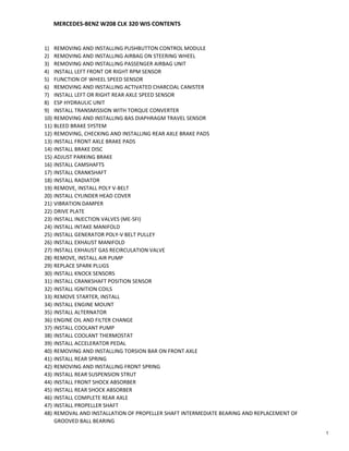
9. GF42.45-P-4550A Location / task / design / function of wheel speed sensor 13.5.96
MODEL 129,
140, 202 as of 1.6.94,
163, 168, 170, 208, 210
with CODE (470a) Anti-lock brake system (ABS)
with CODE (212a) Electronic traction system (ETS)
with CODE (471a) Acceleration slip regulation (ASR)
MODEL 129,
140 as of 1.6.94,
163 up to 31.8.02,
168, 170, 210 with CODE (472a) Electronic Stability Program (ESP)
MODEL 202 with ENGINES 112, 113, 604 with CODE (472a) Electronic Stability Program (ESP)
MODEL 208 with ENGINES 112, 113 with CODE (472a) Electronic Stability Program (ESP)
L6/1 Left front wheel speed sensor
L6/2 Right front wheel speed sensor
ABS only
L6 Rear axle speed sensor
ETS, ASR, ESP only
L6/3 Left rear wheel speed sensor
L6/4 Right rear wheel speed sensor
P42.30-0221-06
Wheel speed sensor, location The front wheelspeed sensors (L6/1 and
L6/2) are mounted on the front steering
knuckle assemblies.
ABS: The rear wheelspeed sensor (L6) is
located on the differential assembly.
ETS, ASR, ESP: The rear wheelspeed
sensors (L6/3 and L6/4) are mounted on the
rear wheel carriers.
Wheel speed sensor, task To supply the current wheel speed to the
ABS, ETS, ASR or ESP control module
(N47-7, N47-2, N47-1 or N47-5).
Wheel speed sensor, design Inductive sensor: Coil with magnetic core
installed at a defined distance from reluctor
on the front wheel hub, the rear halfshafts or
the drive pinion at the rear axle.
Wheel speed sensor, function The magnetic field of the wheel speed
sensor is intersected by the teeth of a rotor.
This changes the magnetic field and the coil
induces an AC voltage. The frequency of
this alternating current, governed by the
number of teeth on the reluctor, fluctuates
to reflect variations in wheelspeed, is
proportional to wheelspeed.
Page 1 of 1© Daimler AG, 8/1/15, G/04/14, gf42.45-p-4550a, Location / task / design / function of wheel speed sensor
MODEL 129, 140, 202 as of 1.6.94, 163, 168, 170, 208, 210 with CODE (470a) Anti-lock brake system (ABS) with CODE (212a) Electronic traction system (ETS) with CODE (471a) Acceleration ...
9
10. AR47.30-P-8212DA Removing and installing activated charcoal canister 18.12.97
MODEL 202, 208 with CODE (491) as of Model Year 99 USA version
77 Activated charcoal canister
Y58/4 Activated charcoal canister shutoff
valve
82/4 Hose clips
A Activated charcoal canister line to
purge control valve
B Activated charcoal canister line to
reservoir
C Activated charcoal canister line to
shutoff valve
P47.30-2010-06
e d Removing, installing
a Risk of explosion from ignition. Risk of No fire, naked flame or smoking. AS47.00-Z-0001-01ADanger!
poisoning from inhaling and swallowing fuel. Pour fuels only into suitable and
Risk of injury as a result of fuel coming into appropriately marked containers.
contact with skin and eyes. Wear protective clothing when handling fuel.
1 Remove wheel housing liner Rear left
2 Detach lines (arrow) at shutoff valve (58/4)
3 Slacken hose clips (82/4) and detach lines
(A) and (B)
4 Remove activated charcoal canister (77)
i GF47.10-P-3004AOn-board refuelling vapor recovery
ORVR function
5 Install in the reverse order
Page 1 of 1© Daimler AG, 8/1/15, G/04/14, ar47.30-p-8212da, Removing and installing activated charcoal canister
MODEL 202, 208 with CODE (491) as of Model Year 99 USA version
10
11. AR42.40-P-0820A Remove/install left or right rear axle speed sensor 8.12.11
MODEL 129, 140 as of 1.6.94,
170,
202 as of 1.6.94,
208, 210
with CODE (471) Acceleration slip regulation (ASR)
with CODE (212) Electronic traction system (ETS)
MODEL 129, 140, 170, 202, 208, 210 with CODE (472) Electronic Stability Program (ESP)
MODEL 203
MODEL 209 except CODE (P98) Black Series
Shows model 202
P42.40-0218-06
Modification notes
29.11.11 Long-life grease repair materials replaced by hot-grease
paste
Fig. item etc. Work instructions
a Self-locking bolts securing rear axle rpm p Installation: Replace bolts in order to
sensor prevent them from becoming loose.
n *BA42.40-P-1002-01AModels 129, 140, 170, 202, 208, 210,
n *BA42.30-P-1001-02AModel 203, 209
L6/3, L6/4 Left/right rear axle rpm sensor i Installation: Check rotor on wheel hub
for damage. Pay attention to cleanliness of
magnetic tip.
i Installation: Apply light coating of grease
to bore in wheel carrier.
Hot lubricating paste *BR00.45-Z-1005-06A
n Acceleration Slip Regulation (ASR)
Number Designation Model 129 Model 140 Model 170 Model 202
BA42.40-P-1002-01A Self-locking bolt, rear axle speed sensor Nm 8 8 8 8
n Acceleration Slip Regulation (ASR)
Number Designation Model 208 Model 210
Page 1 of 2© Daimler AG, 8/1/15, G/04/14, ar42.40-p-0820a, Remove/install left or right rear axle speed sensor
MODEL 129, 140 as of 1.6.94, 170, 202 as of 1.6.94, 208, 210 with CODE (471) Acceleration slip regulation (ASR) with CODE (212) Electronic traction system (ETS) MODEL 129, 140, 170, 202, ...
11
12. BA42.40-P-1002-01A Self-locking bolt, rear axle speed sensor Nm 8 8
n Rear axle rpm sensor
Number Designation Model 203 Model 209
BA42.30-P-1001-02A Self-locking bolt of rear axle rpm sensor to wheel Nm 8 8
carrier
Repair materials
Number Designation Order number
BR00.45-Z-1005-06A Paste, hot lubrication 1 kg, DB supply specification 6879.20 A 000 989 76 51
Page 2 of 2© Daimler AG, 8/1/15, G/04/14, ar42.40-p-0820a, Remove/install left or right rear axle speed sensor
MODEL 129, 140 as of 1.6.94, 170, 202 as of 1.6.94, 208, 210 with CODE (471) Acceleration slip regulation (ASR) with CODE (212) Electronic traction system (ETS) MODEL 129, 140, 170, 202, ...
12
13. AR42.40-P-0816A Remove/install ETS/ASR/ESP hydraulic unit 13.1.10
MODEL 129, 140 as of 1.6.94,
170,
202 as of 1.6.94,
208, 210
with CODE (212) Electronic traction system (ETS)
with CODE (471) Acceleration slip regulation (ASR)
MODEL 129, 140, 210 with CODE (472) Electronic Stability Program (ESP)
MODEL 202, 208 with ENGINE 112, 113 with CODE (472) Electronic Stability Program (ESP)
Connectors of ESP hydraulic unit
(A7/3)
VA to front axle connector of charging piston unit
RA to rear axle connector of charging piston unit
VL To left front wheel brake
FR To right front wheel brake
RL To left rear wheel brake
RR To right rear wheel brake
m1 High-pressure/return pump
P42.45-0205-02
Connectors of Teves hydraulic unit
ASR/ETS (A7/3)
VL To left front wheel brake
FR To right front wheel brake
RL To left rear wheel brake
RR To right rear wheel brake
V to tandem master brake cylinder of front axle
H to tandem master brake cylinder of rear axle
P42.40-0298-02
Page 1 of 3© Daimler AG, 8/1/15, G/04/14, ar42.40-p-0816a, Remove/install ETS/ASR/ESP hydraulic unit
MODEL 129, 140 as of 1.6.94, 170, 202 as of 1.6.94, 208, 210 with CODE (212) Electronic traction system (ETS) with CODE (471) Acceleration slip regulation (ASR) MODEL 129, 140, 210 with ...
13
14. Connectors of hydraulic unit, Bosch
ASR V/ETS (A7/3)
V to tandem master brake cylinder of
front axle
H to tandem master brake cylinder of
rear axle
VL To left front wheel brake
FR To right front wheel brake
RL To left rear wheel brake
RR To right rear wheel brake
P42.40-0211-06
Figure item, etc. Work instructions
a Risk of poisoningDanger! caused by swallowing Only pour brake fluid into suitable and AS42.50-Z-0001-01A
brake fluid. Risk of injury caused by brake appropriately marked containers. Wear
fluid coming into contact with skin and eyes. protective clothing and eye protection when
handling brake fluid.
p Brake fluid notes AH42.50-P-0001-01A
p Notes on repairs to brake system AH42.00-P-0003-01A
i Ignition OFF
i Bleed brake system AR42.10-P-0010AFollowing
completion of
installation
i Read out fault memory and erase AD00.00-P-1000AZFollowing
completion of
installation
a
Hydraulic lines l *000589750300Ring spanner insert with size 11 mm.
l *140589000300Ring spanner insert with size 12 mm.
n *BA42.40-P-1001-01A(ASR/ETS)
n *BA42.45-P-1003-01A(ESP)
Model 202, 208 *BA42.45-P-1003-01B
pRisk of confusion! Before unbolting, mark
hydraulic line at appropriate connector.
p l *129589009100Use plugs to seal off hydraulic lines
and connection fittings.
p Installation: Pay attention to the
markings when screwing on the hydraulic
lines. Do not misconnect hydraulic lines. If
necessary check installation of lines to the
appropriate wheel.
a Plastic caps i Installation: Install with the lug
downwards.
A7/3 Hydraulic unit (ETS) iModel 170: pull out upwards out of the
rubber plugs.
n Acceleration Slip Regulation (ASR)
Number Designation Model 129 Model 140 Model 202 Model 210
Page 2 of 3© Daimler AG, 8/1/15, G/04/14, ar42.40-p-0816a, Remove/install ETS/ASR/ESP hydraulic unit
MODEL 129, 140 as of 1.6.94, 170, 202 as of 1.6.94, 208, 210 with CODE (212) Electronic traction system (ETS) with CODE (471) Acceleration slip regulation (ASR) MODEL 129, 140, 210 with ...
14
15. BA42.40-P-1001-01A Brake line to ASR / ETS hydraulic unit Nm 15 15 15 15
n Acceleration Slip Regulation (ASR)
Number Designation Model 170 Model 208
BA42.40-P-1001-01A Brake line to ASR / ETS hydraulic unit Nm 15 15
n Electronic Stability Program (ESP)
Number Designation Model 129 Model 140 Model 210
BA42.45-P-1003-01A Brake line to ESP hydraulic unit Nm 15 15 15
n Electronic Stability Program (ESP)
Number Designation Model
208 with
engine
111
BA42.45-P-1003-01B Union nut, brake line to ESP hydraulic unit M10 1 Nm 14
M12 1 Nm 16
n Electronic Stability Program (ESP)
Number Designation Model Model
202 with 208 with
engines engine
112, 113 112, 113
BA42.45-P-1003-01B Union nut, brake line to ESP hydraulic unit M10 1 Nm 14 14
M12 1 Nm 16 16
000 589 75 03 00 129 589 00 91 00 140 589 00 03 00
Box wrench bit Set of stop plugs Box wrench bit
Page 3 of 3© Daimler AG, 8/1/15, G/04/14, ar42.40-p-0816a, Remove/install ETS/ASR/ESP hydraulic unit
MODEL 129, 140 as of 1.6.94, 170, 202 as of 1.6.94, 208, 210 with CODE (212) Electronic traction system (ETS) with CODE (471) Acceleration slip regulation (ASR) MODEL 129, 140, 210 with ...
15
16. AR27.10-P-0500B Remove/install transmission with torque converter 30.4.09
TRANSMISSION 722.6 in MODEL 129, 140, 170, 202, 208, 210
P27.10-0251-09
4 Oil drain screw, transmission oil pan 61 Oil filler pipe 66 Propeller shaft
9 Torque converter oil drain screw 62 Shield 80 Parking shift lock
26 Plug-in connector 63 Shift rod 81 Torque converter cover
33 Range selector lever 64 Exhaust bracket 94 Exhaust system
46 Ground strap 65 Engine support with engine mount 95 Screw
49 Oil cooling lines
Modification notes
13.1.06 Oil drain bolt to torque converter Transmission 722.6 *BA27.20-P-1001-01C
Bolt, torque converter to drive plate Transmission 722.6 *BA27.20-P-1002-01C
e d Remove/install
p Notes on self-locking nuts and bolts AH00.00-N-0001-01A
p Before starting work the area around the oil
cooler lines (49) must be thoroughly cleaned
in the separation point areas on the
transmission. Even the smallest dirt particles,
introduced into the hydraulic components,
can lead to malfunctions and a total failure
of the transmission
1 Detach ground line from battery p Insulate ground line as a protection
against unintentional contact of detached
ground line with ground point of battery.
Model 129, 170, 202, 208, 210 AR54.10-P-0003A
Model 140 ra54001400003x
p Notes on battery AH54.10-P-0001-01A
2.1 Detach oil filler pipe (61) from engine Model 129, 140 with engine 119 AR27.10-P-0500-04A
Model 202, 210 with engine 111, 604, 605,
606
2.2 Remove oil filler pipe (61) Models 129, 140 with engine 120 AR27.10-P-0500-04A
Model 210 with engine 119
3 Remove oil drain screw (4) from the n *BA27.10-P-1001-03A
transmission oil pan and drain transmission
oil
iIf the transmission oil is burnt or
interspersed with abrasive particles, the oil
cooler lines (49) and oil cooler must be
flushed out:
Flush oil cooler and oil cooling lines AR27.55-P-0001A
4 Remove oil drain screw (9) from torque n *BA27.20-P-1001-01C
converter and drain transmission oil
Page 1 of 4© Daimler AG, 8/1/15, G/04/14, ar27.10-p-0500b, Remove/install transmission with torque converter
TRANSMISSION 722.6 in MODEL 129, 140, 170, 202, 208, 210
16
17. pIf the transmission oil pan contains metal
shavings, drain the transmission fluid from
the torque converter via the drain hole
through a clean cloth.
If the cloth contains metal swarf after
draining the transmission oil, it is then
necessary to replace the torque converter.
In case of doubt, flush the torque converter
with ATF only.
Metal shavings can damage the
transmission at a later stage.
k Oil drain screw (9) at torque converter no Transmission 722.6 BT27.20-P-0001-01A
longer required
5.1 Remove shield (62) and detach 13-pin plug Shield (62) discontinued on model 129 with AR27.10-P-0500-01A
(26) engine 119 and engine 120 as of 03.96
6 Detach control cable / gears for parking lock i AR27.60-P-0500-05ATransmission models
interlock (80) from transmission 722.620 up to end no. 0001680
722.621 up to end no. 0001976
722.622 up to end no. 0016286
i AR27.60-P-0500-05BTransmission models
722.60/61/63/66/69
722.620 as of end no. 0001681
722.621 as of end no. 0001977
722.622 as of end no. 0016287
722.623/624/625/627/628/629
pTo install and remove place the selector
lever or range selector lever (33) in
position"P" and leave in position "P" with the
cable/transmission removed.
g Installation: Check function of parking
shift lock (80).
7.1 Detach retaining plate for rack-and-pinion Model 210 4MATIC
steering See:
Remove/install rack-and-pinion steering. AR46.20-P-0600A
8 Remove cover (81) and unscrew bolts (95) n *BA27.20-P-1002-01C
from torque converter
9 Detach left and right oil cooling line (49) on
transmission
10 Remove shift rod (63); to do this, remove l *210589003700Pliers
lsecuring clips using pliers
i AR27.60-P-0980BInstallation: Adjust shift rod (63).
11 Remove exhaust bracket (64).
12.1 Detach exhaust system (94) at rear with V- Model 129, 140, 210 with engine 119
belt
12.2 Remove exhaust system (94) as from Models 129, 140 with engine 120 AR49.10-P-7000F
connector
13 Remove fan shroud from radiator Model 210 with engine 119
Model 140 with engine 606
14 Remove engine support with rear engine Engine 112, 113 AR22.10-P-1160HV
mount (65)
Engine 119 ra22001192120x
Engine 120 AR22.10-P-1160AO
Model 202, 210 with engine 111, 604, 605, AR22.10-P-1160HB
606
Model 202, 210 with Engine 611, 612, 613 AR22.10-P-1160HC
15 Detach front propeller shaft (66) n *BA41.10-P-1001-01A
16.1 Detach propeller shaft from transfer case n *BA33.30-P-1003-02AModel 210 4MATIC
17 Detach ground strap (46) from transmission
18 Unscrew transmission from crankcase and pSecure torque converter to prevent it
kuse transmission platform to remove from falling out.
downwards at an angle
19.1 l If necessary AR27.20-P-0500-01BRemove torque converter using grab
handles
iInstallation: Grease the torque converter
lightly on drive flange.
Multipurpose paste *BR00.45-Z-1009-06A
l *168589006200
20 Install in the reverse order
21 Check oil level in automatic transmission, AR27.00-P-0100AC
correct if necessary
22 Read out fault memory with STAR
DIAGNOSIS and erase if necessary
23.1 Perform transmission adaptation Transmission adaptation must be performed
after the transmission is changed or repaired.
Page 2 of 4© Daimler AG, 8/1/15, G/04/14, ar27.10-p-0500b, Remove/install transmission with torque converter
TRANSMISSION 722.6 in MODEL 129, 140, 170, 202, 208, 210
17
18. a Risk of accident Secure vehicle to prevent it from moving byDanger! caused by vehicle starting AS00.00-Z-0005-01A
off by itself when engine is running. Risk of itself.
injury Wear closed and snug-fitting work clothes.caused by contusions and burns
during starting procedure or when working Do not touch hot or rotating parts.
near the engine as it is running
24 Perform engine test run and check
transmission for proper function and
leaktightness.
n Torque converter
Number Designation Trans-
mission
722.6
except
722.648
BA27.20-P-1001-01C Oil drain bolt to torque M8 Nm 10
converter
M10 Nm 15
BA27.20-P-1002-01C Bolt, torque converter Straight threaded M8 Nm 42
to drive plate connection
Angled threaded Stage 1 Nm 4
connection
Stage 2 Nm 30
Stage 3 ° 90
n Oil pan, automatic transmission
Number Designation Trans-
mission
722.6
except
722.628/
648/649
BA27.10-P-1001-03A Drain plug on transmission oil pan Nm 20
n Front axle shaft
Number Designation Model
210.08/28
BA33.30-P-1003-02A Bolt, front axle gear propeller shaft Nm 30
to transfer case flange
nPropeller shaft
Number Designation Model Model Model
129 140 170
Page 3 of 4© Daimler AG, 8/1/15, G/04/14, ar27.10-p-0500b, Remove/install transmission with torque converter
TRANSMISSION 722.6 in MODEL 129, 140, 170, 202, 208, 210
18
19. BA41.10-P-1001-01A Self-locking nut, flexible coupling to transmission M10 Nm 40 - 40
or front propeller shaft
M12 Nm 60 60 60
nPropeller shaft
Number Designation Model Model Model
202 208 210
BA41.10-P-1001-01A Self-locking nut, flexible coupling to transmission M10 Nm 40 40 40
or front propeller shaft
M12 Nm 60 60 60
168 589 00 62 00 210 589 00 37 00
Grab handle Pliers
Repair materials
Number Designation Order number
BR00.45-Z-1009-06A Multipurpose paste A 000 989 80 51 10
Page 4 of 4© Daimler AG, 8/1/15, G/04/14, ar27.10-p-0500b, Remove/install transmission with torque converter
TRANSMISSION 722.6 in MODEL 129, 140, 170, 202, 208, 210
19
20. AR42.31-P-6002A Removing and installing BAS diaphragm travel sensor 7.9.96
MODEL 129, 140 as of 1.12.96,
170, 202 as of 1.6.97,
208, 210 as of 1.2.97
Shown on model 208
8 Vacuum line
16b Locking ring
A7/7b1 BAS diaphragm travel sensor
A7/7x1 Diaphragm travel sensor connector
P42.31-0253-11
Shown on model 210
8 Vacuum line
16b Locking ring
A7/7b1 BAS diaphragm travel sensor
A7/7x1 Diaphragm travel sensor connector
P42.31-0216-11
Modification notes
1.8.99 Check diaphragm travel sensor for labeling iNew parts are marked with a white,
yellow or blue "D" (Figure 1). The label may
be on the side away from you.
e d Removing, installing
i Notes on brake booster AH43.20-P-0001-01A
1 Operate brake pedal several times until p The diaphragm travel sensor sealing ring
vacuum in brake booster is reduced. may be sucked into the brake booster if
vacuum is present.
If this happens, the brake booster must be
replaced.
2 Unplug BAS diaphragm travel sensor
connector (A7/7x1)
3 Remove locking ring (16b) Use a suitable tool, e.g. angled scriber
(arrow).
i Installation: Replace locking ring and
ensure that it is correctly seated.
p Different manufacturers use different
locking rings.
Page 1 of 2© Daimler AG, 8/1/15, G/04/14, ar42.31-p-6002a, Removing and installing BAS diaphragm travel sensor
MODEL 129, 140 as of 1.12.96, 170, 202 as of 1.6.97, 208, 210 as of 1.2.97
20
21. 4 Pull out BAS diaphragm travel sensor i Installation: Rub a little spirit or soapy
(A7/7b1) water onto the front of the diaphragm travel
sensor so that O-ring slides correctly when
inserted.
5 Replace O-ring i Installation: Insert O-ring into groove in
brake booster and ensure that it is correctly
seated.
6 Install in the reverse order
g Checking
7 Start engine iOperate brake several times.
8 Switch off engine
9 Check diaphragm travel sensor for leaks iThere must not be any air flow noises
audible at the brake booster.
Page 2 of 2© Daimler AG, 8/1/15, G/04/14, ar42.31-p-6002a, Removing and installing BAS diaphragm travel sensor
MODEL 129, 140 as of 1.12.96, 170, 202 as of 1.6.97, 208, 210 as of 1.2.97
21
22. AR42.10-P-0010A Bleed brake system 10.11.11
MODEL 129, 140, 170, 202, 208, 210
P42.10-0270-09
Bleeding
a Risk of poisoningDanger! caused by swallowing Only pour brake fluid into suitable and AS42.50-Z-0001-01A
brake fluid. Risk of injury caused by brake appropriately marked containers. Wear
fluid coming into contact with skin and eyes. protective clothing and eye protection when
handling brake fluid.
p Brake fluid notes AH42.50-P-0001-01A
p Notes on repairs to brake system AH42.00-P-0003-01A
1 Actuate master brake cylinder switchover Model 129.076, 140.04/05/06/07 AR42.10-P-0010-01A
valve (Y61)
iThe switchover valve (Y61) must be
opened so that the annular passage in the
master brake cylinder is bled.
y Wiring harness for actuation of switchover Model 129.067 with ESP WF58.50-P-4210-01A
valve
l *201589009900Electrical connection set
2 Connect brake fluid changing equipment pPay attention to manufacturer's operating
instructions.
iBleeding pressure 2 bar.
Brake fluid change unit
gotis://B_42/43.2_01
j *BF42.10-P-1001-01ABrake fluid
3 Carrying out bleeding operation Model 129, 140 without code 471 ASR, AR42.10-P-0010-02A
without code 472 ESP
Models 129, 140 with code 471 ASR and
ETS as of 1. 6. 94
Model 129.059/064/068 with/without ESP
with engine 112, 113
Model 170
Model 202 without code 471 ASR up to
31.5.94
Model 202 with code 471 ASR as of 1.6.94
Model 202 with ESP
Model 208
Model 210 without ESP, model 210 with ESP,
except model 210.072/272 with ESP
Model 129 with ASR (code 471a) up to AR42.10-P-0010-02B
31.5.94
Model 140 with ASR (code 471a) up to AR42.10-P-0010-02C
31.5.94
Model 202 with ASR (code 471a) up to AR42.10-P-0010-02D
31.5.94
Model 129.067/076, 140 with ESP, AR42.10-P-0010-02E
Model 210.072/272 with ESP
Page 1 of 5© Daimler AG, 8/1/15, G/04/14, ar42.10-p-0010a, Bleed brake system
MODEL 129, 140, 170, 202, 208, 210
22
23. Front axle, model 129, 140:
n *BA42.10-P-1002-10IBleed screw to brake caliper
Front axle model 170:
n *BA42.10-P-1002-10PBleed screw to brake caliper
Front axle model 202:
n *BA42.10-P-1002-10KBleed screw to brake caliper
Front axle model 208:
n *BA42.10-P-1002-10DBleed screw to brake caliper
Front axle model 210:
n *BA42.10-P-1002-10FBleed screw to brake caliper
Rear axle, model 129, 140:
n *BA42.10-P-1002-12IBleed screw to brake caliper
Rear axle model 170:
n *BA42.10-P-1002-12PBleed screw to brake caliper
Rear axle model 202:
n *BA42.10-P-1002-12KBleed screw to brake caliper
Rear axle model 208:
n *BA42.10-P-1002-12DBleed screw to brake caliper
Rear axle model 210:
n *BA42.10-P-1001-12FBleed screw to brake caliper
l *140589030900Socket wrench
4 Disconnect the brake fluid changing j *BF42.10-P-1001-01ABrake fluid
equipment, check the brake fluid level and
correct if necessary
n Front axle brake caliper
Number Designation Model Model Model
129 140 140 with
without special
special protectio
protection n
BA42.10-P-1002-10I Bleed screw to brake caliper Nm 7 7 7
n Front axle brake caliper
Number Designation Model
170
BA42.10-P-1002-10P Bleed screw to brake caliper Nm 7
n Front axle brake caliper
Number Designation Model Model
202.018/020/ 202.024/025/
022/023/033/ 026/029/082/
078/080/081/ 085/086/088/
083/087/093/ 089/128/188,
120/121/122/ Model
125/133/134/ 202.028
180/182/193/ as of 09/95
194,
Model
202.028
up to 08/95
Page 2 of 5© Daimler AG, 8/1/15, G/04/14, ar42.10-p-0010a, Bleed brake system
MODEL 129, 140, 170, 202, 208, 210
23
24. BA42.10-P-1002-10K Bleed screw to brake caliper Nm 7 7
n Front axle brake caliper
Number Designation Model
208
BA42.10-P-1002-10D Bleed screw to brake caliper Nm 7
n Front axle brake caliper
Number Designation Model
210
BA42.10-P-1002-10F Bleed screw to brake caliper M8 Nm 7
n Rear axle brake caliper
Number Designation Model Model
129 140
BA42.10-P-1002-12I Bleed screw to brake caliper Nm 7 7
n Rear axle brake caliper
Number Designation Model Model
170.435/ 170.466
444/445/
447/449/
465
BA42.10-P-1002-12P Bleed screw to brake caliper Nm 7 7
n Rear axle brake caliper
Number Designation Model
202
BA42.10-P-1002-12K Bleed screw to brake caliper Nm 7
n Rear axle brake caliper
Number Designation Model
208
Page 3 of 5© Daimler AG, 8/1/15, G/04/14, ar42.10-p-0010a, Bleed brake system
MODEL 129, 140, 170, 202, 208, 210
24
25. BA42.10-P-1002-12D Bleed screw to brake caliper Nm 7
n Rear axle brake caliper
Number Designation Model
210
BA42.10-P-1001-12F Bleed screw to brake caliper Nm 7
j Brake fluid
Number Designation Model Model
129 140
0.45 to 0.6 0.7...0.9Brake fluid Filling capacity LitersBF42.10-P-1001-01A
Specifications for Operating Sheet BB00.40-P-0330-01A BB00.40-P-0330-01A
Fluids
Sheet BB00.40-P-0331-00A BB00.40-P-0331-00A
j Brake fluid
Number Designation Model Model
170 202
0.45 to 0.6 0.45 to 0.6Brake fluid Filling capacity LitersBF42.10-P-1001-01A
Specifications for Operating Sheet BB00.40-P-0330-01A BB00.40-P-0330-01A
Fluids
Sheet BB00.40-P-0331-00A BB00.40-P-0331-00A
j Brake fluid
Number Designation Model Model
208 210
0.45 to 0.6 0.45 to 0.6Brake fluid Filling capacity LitersBF42.10-P-1001-01A
Specifications for Operating Sheet BB00.40-P-0330-01A BB00.40-P-0330-01A
Fluids
Sheet BB00.40-P-0331-00A BB00.40-P-0331-00A
Page 4 of 5© Daimler AG, 8/1/15, G/04/14, ar42.10-p-0010a, Bleed brake system
MODEL 129, 140, 170, 202, 208, 210
25
26. 201 589 00 99 00 140 589 03 09 00
Electrical connection set Socket wrench
Page 5 of 5© Daimler AG, 8/1/15, G/04/14, ar42.10-p-0010a, Bleed brake system
MODEL 129, 140, 170, 202, 208, 210
26
27. AR42.10-P-1700AM Removing, checking and installing rear axle brake pads 11.3.10
MODEL 129, 140, 170, 202, 208, 210
P42.10-0242-09
Fixed brake caliper with two retaining pins (41) on rear axle
P42.10-0425-09
Fixed brake caliper with one retaining pin (41) on rear axle
e d Remove/install
a Risk of poisoningDanger! caused by swallowing Only pour brake fluid into suitable and AS42.50-Z-0001-01A
brake fluid. Risk of injury caused by brake appropriately marked containers. Wear
fluid coming into contact with skin and eyes. protective clothing and eye protection when
handling brake fluid.
a Risk of injuryDanger! to skin and eyes caused by Wear safety gloves, protective clothing and AS00.00-Z-0002-01A
handling hot or glowing objects. safety glasses, if necessary.
p Notes on repairs to brake system AH42.00-P-0003-01A
p Brake fluid notes AH42.50-P-0001-01A
1 Unscrew the cap on the brake fluid iIn order to prevent the expansion
expansion reservoir and suction off some reservoir overflowing when pressing back the
brake fluid brake pistons (47)
2 Remove rear wheels
e Remove/install wheels, rotate if necessary AP40.10-P-4050Z
Page 1 of 3© Daimler AG, 8/1/15, G/04/14, ar42.10-p-1700am, Removing, checking and installing rear axle brake pads
MODEL 129, 140, 170, 202, 208, 210
27
28. 3 Remove brake pad contact sensor i Installation: Replace defective brake pad
contact sensor.
p Notes on installing brake pad wear sensor AH42.10-P-0003-01A
contact sensors
4 Drive out retaining pins (41) using punch iInstallation: Knock retaining pins (41) all
(035) and remove retaining spring the way in.
5 Pull brake pads (43) out of the brake caliper pWhen pressing out seized brake pads
(31) (43) insert wedge between lever (034) and
brake caliper (31) to prevent damage.
iBrake pads (43) are to be disposed of as
special waste. The local authorities can
provide information regarding whether
disposal is also permitted as industrial waste
similar to domestic waste.
i Installation: Only sets of brake pads
(43) approved by Mercedes-Benz may be
installed. Install brake pads (43) with
peripheral damping (a and c) ungreased. On
brake pads (43) without peripheral damping
on the side surfaces (arrows) coat with some
brake pad paste.
l *123589133300Lever
l *601589076300Wedge
Brake pad paste *BR00.45-Z-1003-06A
g Checking
6 Check brake pad thickness and brake disks iReplace brake pads (43) and brake disks
in sets if necessary.
e Inspect condition of brake disks AP42.10-P-4258AM
e Check brake lining thickness Model 129, 140 as of 1.7.93 AP42.10-P-4253AM
Model 170, 202, 208, 210
iIf the brake pads (43) have worn down to
beyond the wear limit, the bar between the
sealing groove and dust cap may be
damaged; therefore:
Inspect brake system for leaks with pressure AR42.10-P-0015A
tester.
7 Press back brake piston (47) using resetting iDo not bend heat shield. If brake pads
device (031) (43) have been removed from several brake
calipers (31), their brake pistons (47) must
be secured beforehand with wedges to
prevent them from falling out .
i Do not fit the pusher tool (031) to the
brake disk, but push back the opposite brake
pistons (47) simultaneously. If brake pistons
(47) are sluggish:
Repair brake caliper (31). AR42.10-P-0151A
l *000589524300Resetting device
l *601589076300Wedge
m Clean
8 Clean contact surfaces of brake pads (43) iDo not damage boots of brake pistons
using brake caliper brush (030) (47).
l *000589266800Brake caliper brush
9 Install in the reverse order
a Risk of accidentDanger! when commissioning the Before starting engine, actuate brake pedal AS42.50-Z-0002-01A
vehicle due to a lack of braking effect when several times until the pressure is built up
the service brake is operated for the first and maintained in the brake system.
time after repair work
10 Operate the brake pedal several times until iFirm resistance should be noticeable at
the brake pads (43) contact the brake disks the brake pedal.
g Checking
11 Check brake fluid level, correct if necessary
e Brake system - inspect fluid level AP42.10-P-4210Z
123 589 13 33 00 000 589 26 68 00 000 589 52 43 00 601 589 07 63 00
Lever Brake caliper brush Pusher tool Wedge
Page 2 of 3© Daimler AG, 8/1/15, G/04/14, ar42.10-p-1700am, Removing, checking and installing rear axle brake pads
MODEL 129, 140, 170, 202, 208, 210
28
29. Repair materials
Number Designation Order number
BR00.45-Z-1003-06A Brake pad paste replaced by: A 001 989 94 51 A 001 989 10 51
Page 3 of 3© Daimler AG, 8/1/15, G/04/14, ar42.10-p-1700am, Removing, checking and installing rear axle brake pads
MODEL 129, 140, 170, 202, 208, 210
29
30. AR42.10-P-1600BM Remove/check/install front axle brake pads 7.2.08
MODEL 170.435 /444 /445 /447 /449 /465, 202.024 /025 /026 /029 /082 /085 /086 /088 /089 /128 /188, 208.335 /344 /345
/347 /348 /365 /435 /444 /445 /447 /448 /465
MODEL 202.028 as of 1.9.95,
210.00 /01 /02 /035 /037 /04 /05 /06 /081 /082,
210.083 up to 7.2.99,
210.20 /21 /22 /23 /24 /26 /282,
210.283 up to 7.2.99,
210.60 /61 /663 except CODE (957) AMG engineering package
MODEL 210.070
with CODE (491) USA version
with CODE (498) Japan version
with CODE (625) Australia version
MODEL 208.370 /470 with CODE (491) USA version
P42.10-0268-09
e d Remove/install
a Risk of poisoningDanger! caused by swallowing Only pour brake fluid into suitable and AS42.50-Z-0001-01A
brake fluid. Risk of injury caused by brake appropriately marked containers. Wear
fluid coming into contact with skin and eyes. protective clothing and eye protection when
handling brake fluid.
a Risk of injuryDanger! to skin and eyes caused by Wear safety gloves, protective clothing and AS00.00-Z-0002-01A
handling hot or glowing objects. safety glasses, if necessary.
p Notes on repairs to brake system AH42.00-P-0003-01A
p Brake fluid notes AH42.50-P-0001-01A
p Notes on self-locking nuts and bolts AH00.00-N-0001-01A
1 Unscrew the cap on the brake fluid iIn order to prevent the expansion
expansion reservoir and suction off some reservoir overflowing when pressing back the
brake fluid brake pistons.
2 Remove the front wheels
e Remove/install wheels, rotate if necessary AP40.10-P-4050Z
3 Unhook spring (31d)
4 Remove brake pad contact sensor i Installation: Replace defective contact
sensors.
p Notes on installing brake pad wear sensor AH42.10-P-0003-01A
contact sensors
5 Detach covers (31b) and remove guide pins n *BA42.10-P-1003-10DModel 208
(31c)
n *BA42.10-P-1003-10FModel 210
n *BA42.10-P-1003-10PModel 170
n *BA42.10-P-1003-10KModel 202
Page 1 of 3© Daimler AG, 8/1/15, G/04/14, ar42.10-p-1600bm, Remove/check/install front axle brake pads
MODEL 170.435 /444 /445 /447 /449 /465, 202.024 /025 /026 /029 /082 /085 /086 /088 /089 /128 /188, 208.335 /344 /345 /347 /348 /365 /435 /444 /445 /447 /448 /465 MODEL 202.028 as of 1.9.95, ...
30
31. 6 Remove floating brake caliper (31a) with pAttach floating caliper (31a) to vehicle so
inner brake pad that it is free of tension. Do not kink or
tension brake hose, as otherwise it will be
damaged.
7 Remove brake pads (31g) iBrake pads (31g) are to be disposed of
as special waste. The local authorities can
provide information regarding whether
disposal is also permitted as industrial waste
similar to domestic waste.
i Installation: Only the brake pads (31g)
approved by Mercedes-Benz may be built-in
as a set. Install brake pads (31g) without
grease. Insert inner brake pad with riveted
on spring (arrow) in brake piston, insert
outer brake pad in brake caliper support
(33).
g Checking
8 Check brake pad thickness and brake disks iOnly replace brake pads (31g) and brake
disks in complete sets if necessary.
e Inspect condition of brake disks AP42.10-P-4258AM
e Check brake lining thickness i AP42.10-P-4253AMIf the brake pads (31g) have worn down
to beyond the wear limit, the bar between
the sealing groove and dust cap may be
damaged; therefore:
Inspect brake system for leaks with pressure AR42.10-P-0015A
tester.
9 Check floating caliper (31a) for leaks and iIf floating brake caliper (31a) is leaky or
dust boot (47) for signs of damage and dust boot (47) is damaged or not seated
correct seating correctly:
Repair floating caliper:
Except model 170.444/449/465, AR42.10-P-0152B
Model 202.088,
Model 208.344/348/444/448
Model 170.444/449/465,
Model 202.088,
Model 208.344/348/444/448
10 Press back brake piston using resetting pIf brake pads (31g) have been removed
device (031). from several brake calipers, secure their
brake pistons beforehand with wedges to
prevent them from falling out . If the brake
piston is difficult to move:
Repair floating caliper:
Except model 170.444/449/465, AR42.10-P-0152B
Model 202.088,
Model 208.344/348/444/448
Model 170.444/449/465,
model 202.088,
model 208.344/348/444/448
l *000589524300Resetting device
l *601589076300Wedge
m Clean
11 Clean contact surfaces of brake pads (31g) iDo not damage dust boot (47).
at floating caliper (31a) and brake caliper
support (33)
l *000589266800Brake caliper brush
12 Install in the reverse order
a Risk of accidentDanger! when commissioning the Before starting engine, actuate brake pedal AS42.50-Z-0002-01A
vehicle due to a lack of braking effect when several times until the pressure is built up
the service brake is operated for the first and maintained in the brake system.
time after repair work
13 Operate the brake pedal several times until iFirm resistance should be noticeable at
the brake pads (31g) contact the brake disks the brake pedal.
14 Inspect fluid level in expansion reservoir,
adjust to correct level if necessary
e Brake system - inspect fluid level AP42.10-P-4210Z
n Front axle brake caliper
Number Designation Model
170
Page 2 of 3© Daimler AG, 8/1/15, G/04/14, ar42.10-p-1600bm, Remove/check/install front axle brake pads
MODEL 170.435 /444 /445 /447 /449 /465, 202.024 /025 /026 /029 /082 /085 /086 /088 /089 /128 /188, 208.335 /344 /345 /347 /348 /365 /435 /444 /445 /447 /448 /465 MODEL 202.028 as of 1.9.95, ...
31
32. BA42.10-P-1003-10P Guide pin, brake caliper to brake caliper support Nm 25
n Front axle brake caliper
Number Designation Model
202.024/025/
026/029/082/
085/086/088/
089/128/188,
Model
202.028
as of 09/95
BA42.10-P-1003-10K Guide pin on caliper support Nm 25
n Front axle brake caliper
Number Designation Model
208
BA42.10-P-1003-10D Guide pin on caliper support Nm 25
n Front axle brake caliper
Number Designation Model
210
BA42.10-P-1003-10F Guide pin on caliper support Nm 25
000 589 52 43 00 601 589 07 63 00 000 589 26 68 00
Pusher tool Wedge Brake caliper brush
Page 3 of 3© Daimler AG, 8/1/15, G/04/14, ar42.10-p-1600bm, Remove/check/install front axle brake pads
MODEL 170.435 /444 /445 /447 /449 /465, 202.024 /025 /026 /029 /082 /085 /086 /088 /089 /128 /188, 208.335 /344 /345 /347 /348 /365 /435 /444 /445 /447 /448 /465 MODEL 202.028 as of 1.9.95, ...
32
33. AR42.10-P-0220A Remove/install brake disc 8.12.11
MODEL 129, 140, 170, 202, 208, 210
P42.10-2005-09
Modification notes
29.11.11 Long-life grease repair materials replaced by hot-grease Step 5
paste
e d Remove/install
a Risk of injuryDanger! to skin and eyes caused by Wear safety gloves, protective clothing and AS00.00-Z-0002-01A
handling hot or glowing objects. safety glasses, if necessary.
p Notes on repairs to brake system AH42.00-P-0003-01A
1 Remove wheels
e Remove/install wheels, rotate if necessary AP40.10-P-4050Z
2 Release parking brake iOnly if removing brake disks (61) at rear
axle.
3 Check brake lining thickness and brake disks iOnly replace brake pads and brake disks
(61) (61) in complete sets if necessary.
e Check brake lining thickness Model 129, 140 as of 1.7.93, AP42.10-P-4253AM
Model 170, 202, 208, 210
e Inspect condition of brake disks AP42.10-P-4258AM
4 Remove brake disk pDo not detach brake hose, instead attach
brake caliper to vehicle so that it is free of
tension. Do not kink or tension brake hose,
as otherwise it will be damaged.
At the front axle:
Model 129, 140, AR42.10-P-0070AM
Model 208.370 /470 up to 18.1.99 except
code 491 USA version,
model 210.070 up to 7.2.99
except code 491 USA version,
except code 498 Japan version,
except code 625 Australia version,
except code 957 AMG engineering package,
model 210.072 /270 /272 up to 7.2.99
Page 1 of 3© Daimler AG, 8/1/15, G/04/14, ar42.10-p-0220a, Remove/install brake disc
MODEL 129, 140, 170, 202, 208, 210
33
34. Model 202.024 /025 /026 /029 /082 /085 AR42.10-P-0070BM
/086 /088 /089 /128 /188,
Model 170.435 /444 /445 /447 /449 /465,
Model 208.335 /344 /345 /347 /348 /365
/435 /444 /445 /447 /448/ 465,
Model 210.00 /01 /02 /035 /037 /04 /053 /06
/081 /082 /20 /21 /22 /23 /24 /26 /282 /60 /61
/663,
model 210.083 /283 up to 7.2.99,
model 210.070 /270
with code 491 USA version,
with code 498 Japan version,
with code 625 Australia version,
model 208.370 /470 with code 494 USA
version,
model 202.028 as of 1.9.95, 210.055, except
code 957 AMG engineering package
Model 202.018 /020 /022 /023 /078 /080 AR42.10-P-0070CM
/081 /083 /087 /120 /121 /122 /125 /133
/180 /182 /193,
model 202.028 up to 31.8.95 except code
957 AMG engineering package
Model 170.466, 208.374, AR42.10-P-0070DM
model 208.370 /470 as of 19.1.99 except
code 494 USA version,
model 202.033 /093, 210.072 /074 /274 with
code 957 AMG engineering package,
model 210.070 as of 8.2.99,
except code 494 USA version,
except code 498 Japan version,
except code 625 Australia version,
model 210.083 /270 /283 as of 8.2.99
Model 202.028, 210.055 with code 957 AMG AR42.10-P-0070EM
engineering package C 36, E 36
At the rear axle:
Model 129, 140, 170, 202, 208, 210 except AR42.10-P-0080AM
code 957 AMG engineering package
Model 202.028 /033 /093, 210.055 /072 /074 AR42.10-P-0080BM
/274 with code 957 AMG engineering
package
5 Remove locking bolt (64) and remove brake i Installation: Only replace brake disks
disk (61) (61) in pairs. Lightly grease seat of brake
disk (61) and replace the safety bolt (64).
Hot lubricating paste *BR00.45-Z-1005-06A
iModels 129, 140, 202: Ensure that the
dowel pin or roll pins (63) are properly
seated in the brake disk (61).
iModels 202.033 /093, 208.374, 210.072
with code 957 AMG engineering package E
50 AMG 210.074 /274
The left and right brake disks (61) are
different.
Identification:
AMG A210 421 1912 right side
AMG A210 421 1812 left side
iModel 140 up to 3.9.93
When installing new brake disks on front
axle:
Pull out roll pins on front wheel hub. AR42.10-P-0220-01A
y Fixture for pulling out roll pins on front wheel WF58.50-P-4210-02A
hub
n *BA42.10-P-1001-06A
n *BA42.10-P-1002-06A
i Notes on installing brake disks Model 129.067 as of 1.6.1994, 129.076 AH42.10-P-9406-04A
k Front axle brake disks modified Model 129.067 as of 1.6.94 BT42.10-P-9406-01A
n Front axle brake system, function Model 210.072 /272 with code 957 AMG GF42.10-P-0002A
engineering package E 50 AMG
6 Install in the reverse order
7 Adjust parking brake Model 129, 140 as of 1.11.93, 170, 202, 208, AR42.20-P-0540A
210
Model 140 up to 31.10.93 AR42.20-P-0540B
n Brake discs, brake cover plate
Number Designation Model Model Model
129 140 170
Page 2 of 3© Daimler AG, 8/1/15, G/04/14, ar42.10-p-0220a, Remove/install brake disc
MODEL 129, 140, 170, 202, 208, 210
34
35. BA42.10-P-1001-06A Locking bolt of rear axle brake disk Nm 10 10 10
BA42.10-P-1002-06A Locking bolt of front axle brake disk Nm 10 10 10
n Brake discs, brake cover plate
Number Designation Model Model Model
202 208 210.0
BA42.10-P-1001-06A Locking bolt of rear axle brake disk Nm 10 10 10
BA42.10-P-1002-06A Locking bolt of front axle brake disk Nm 10 10 10
n Brake discs, brake cover plate
Number Designation Model
210.2/ 6
BA42.10-P-1001-06A Locking bolt of rear axle brake disk Nm 10
BA42.10-P-1002-06A Locking bolt of front axle brake disk Nm 10
Repair materials
Number Designation Order number
BR00.45-Z-1005-06A Paste, hot lubrication 1 kg, DB supply specification 6879.20 A 000 989 76 51
Page 3 of 3© Daimler AG, 8/1/15, G/04/14, ar42.10-p-0220a, Remove/install brake disc
MODEL 129, 140, 170, 202, 208, 210
35
36. AR42.20-P-0540A Adjust parking brake 21.6.94
MODEL 129, 170, 202, 203, 208, 210
MODEL 140 as from 1.11.93
MODEL 209.3/ 4
P42.20-0222-04
Modification notes
23.8.05 Clearance adjustment value changed to 8 teeth Step 7
g Check
a Risk of deathDanger! caused by vehicle slipping or Align vehicle between the columns of the AS00.00-Z-0010-01A
toppling off of the lifting platform. and position the four support plates below
the lifting platform support points specified by
the vehicle manufacturer.
1.1 Check version of pedal assembly Except model 170
k Parking brake pedal assembly modified BT42.20-P-0510-01A
2.1 Operate parking brake pedal and check Except model 170
pedal travel of parking brake pedal
iIf the pedal travel is not within the
tolerance range:
Adjusting parking brake.
Actuating force on parking brake pedal *BE42.20-P-1001-01C
Notches through which the parking brake *BE42.20-P-1002-01C
pedal must be depressed
2.2 Operate parking brake lever and check travel Model 170
of the parking brake lever
iAdjust parking brake, if the parking brake
lever can be pulled up by more than 3
notches without any adequate braking effect
taking place.
e Remove
3 Raise vehicle at rear
4.1 Slacken adjusting screw (89) Models 129, 170
5 Undo a wheel bolt at the left and right rear pLight alloy wheels must be removed due
wheel to the risk of damage.
e Remove/install wheels, rotate if necessary AP40.10-P-4050Z
Adjust
6 Use screwdriver to rotate adjusting wheel iActuation direction for applying the brake
(105) until the brake shoes abut the parking shoes:
brake drum and the rear wheel or brake disk Right side: Turn the adjusting wheel (105)
can no longer be turned by hand. from the bottom upwards.
Left side: Turn the adjusting wheel (105)
from the top downwards.
k Adjusting mechanism for parking brake Type 140 BT42.20-P-9311-01A
modified
7 Turn back adjusting wheel (105) until the i When loosening the adjusting wheels
wheel or brake disk is able to rotate (105) ensure
completely freely by hand that both sides are turned back by the same
number of teeth (8 teeth).
8.1 Turn in adjusting screw (89) until the brake Model 129, 170
cables no longer sag
g Check
9.1 Operate parking brake pedal several times Except model 170
and check pedal travel of the parking brake
pedal, then release the parking brake
Actuating force on parking brake pedal *BE42.20-P-1001-01C
Page 1 of 3© Daimler AG, 8/1/15, G/04/14, ar42.20-p-0540a, Adjust parking brake
MODEL 129, 170, 202, 203, 208, 210 MODEL 140 as from 1.11.93 MODEL 209.3/ 4
36
37. Notches through which the parking brake *BE42.20-P-1002-01C
pedal must be depressed
9.2 Operate parking brake lever several times, Model 170
check parking brake lever travel, and then
release the parking brake
iTurn in adjusting screw (89) until the
parking brake lever can be actuated by one
tooth with an average force application of
approx. 90 to 120 Nm.
10 Check for unobstructed movement of rear
wheels or brake disks
d Install
11 Fit wheel bolts or light alloy wheels
e Remove/install wheels, rotate if necessary. AP40.10-P-4050Z
Adjustment values for parking brake
Number Designation Model Model
129, Pedal 129, Pedal
assembly with assembly with
pulled notch pushed notch
BE42.20-P-1001-01C Actuating force on parking brake pedal N 170 (-50/+70) 170 (-50/+70)
BE42.20-P-1002-01C Notches through which the parking brake pedal Quantity 1 5
must be depressed
See fig. BT42.20-P-0510-01A BT42.20-P-0510-01A
Adjustment values for parking brake
Number Designation Model Model
140, Pedal 140, Pedal
assembly with assembly with
pulled notch pushed notch
BE42.20-P-1001-01C Actuating force on parking brake pedal N 170 (-50/+70) 170 (-50/+70)
BE42.20-P-1002-01C Notches through which the parking brake pedal Quantity 1 5
must be depressed
See fig. BT42.20-P-0510-01A BT42.20-P-0510-01A
Adjustment values for parking brake
Number Designation Model Model
202, Pedal 202, Pedal
assembly with assembly with
pulled notch pushed notch
BE42.20-P-1001-01C Actuating force on parking brake pedal N 170 (-50/+70) 170 (-50/+70)
BE42.20-P-1002-01C Notches through which the parking brake pedal Quantity 1 5
must be depressed
See fig. BT42.20-P-0510-01A BT42.20-P-0510-01A
Adjustment values for parking brake
Page 2 of 3© Daimler AG, 8/1/15, G/04/14, ar42.20-p-0540a, Adjust parking brake
MODEL 129, 170, 202, 203, 208, 210 MODEL 140 as from 1.11.93 MODEL 209.3/ 4
37
38. Number Designation Model Model
203, Pedal 203, Pedal
assembly with assembly with
pulled notch pushed notch
BE42.20-P-1001-01C Actuating force on parking brake pedal N 170 (-50/+70) 170 (-50/+70)
BE42.20-P-1002-01C Notches through which the parking brake pedal Quantity 1 5
must be depressed
See fig. BT42.20-P-0510-01A BT42.20-P-0510-01A
Adjustment values for parking brake
Number Designation Model Model
208, Pedal 208, Pedal
assembly with assembly with
pulled notch pushed notch
BE42.20-P-1001-01C Actuating force on parking brake pedal N 170 (-50/+70) 170 (-50/+70)
BE42.20-P-1002-01C Notches through which the parking brake pedal Quantity 1 5
must be depressed
See fig. BT42.20-P-0510-01A BT42.20-P-0510-01A
Adjustment values for parking brake
Number Designation Model Model
209, Pedal 209, Pedal
assembly with assembly with
pulled notch pushed notch
BE42.20-P-1001-01C Actuating force on parking brake pedal N 170 (-50/+70) 170 (-50/+70)
BE42.20-P-1002-01C Notches through which the parking brake pedal Quantity 1 5
must be depressed
See fig. BT42.20-P-0510-01A BT42.20-P-0510-01A
Adjustment values for parking brake
Number Designation Model Model
210, Pedal 210, Pedal
assembly with assembly with
pulled notch pushed notch
BE42.20-P-1001-01C Actuating force on parking brake pedal N 170 (-50/+70) 170 (-50/+70)
BE42.20-P-1002-01C Notches through which the parking brake pedal Quantity 1 5
must be depressed
See fig. BT42.20-P-0510-01A BT42.20-P-0510-01A
Page 3 of 3© Daimler AG, 8/1/15, G/04/14, ar42.20-p-0540a, Adjust parking brake
MODEL 129, 170, 202, 203, 208, 210 MODEL 140 as from 1.11.93 MODEL 209.3/ 4
38
39. AR05.20-P-6992AU Remove/install camshafts 29.1.09
ENGINE 112
ENGINE 112.945 in MODEL 463.209 /232 /233 /244 /245 /250
ENGINE 113.962 in MODEL 463.206 /240 /241 /247 /248 /249 /254
ENGINE 113.982 in MODEL 463.243 /246
ENGINE 113 in MODEL 129, 163, 202, 203, 208, 209, 210, 211, 215, 220, 230
P05.20-0303-09
Shown on engine 112 3 Right-hand camshaft locating plate 40° after first ignition
TDC1 Camshaft Hall sensor
4 Camshaft bearing bridge2 Chain tensioner
5 Cable tie
Modification notes
18.6.97 M112: Procedure modified, new special tool. Step 1-14 *112589010300
e Removing
1 Remove cylinder head covers Air filter mounted on vehicle AR01.20-P-5014B
Air filter mounted on engine AR01.20-P-5014BV
2 Position piston of cylinder 1 at 40° after TDC i AR05.10-P-6858VRotate engine at crankshaft in direction
of rotation until 40° marking on belt pulley/
vibration damper is aligned with marking on
timing case cover. The grooves on the
camshafts must be pointing toward the inner
V.
iEngine must not be rotated backwards.
3 Remove chain tensioner (2) Model 129, 463 AR05.10-P-7800C
Model 163 except 163.174 /175
Model 202, 208, 210 with engine 113
Model 170, 202, 203, 208, 209, 210 with AR05.10-P-7800CA
engine 112
Model 163.174/ 175
Model 209.375 /475
Model 209.376 /476 up to 23.4.04
Model 203 with engine 113 AR05.10-P-7800AC
Model 209.376/ 476 as of 24.4.04
Model 211.0 with engine 112, 113 AR05.10-P-7800AM
Model 211.276
Model 215
Model 220, 230 with engine 112, 113
Model 211.2 except 211.276 with engine
112, 113
Model 171 with engine 113
Page 1 of 4© Daimler AG, 8/1/15, G/04/14, ar05.20-p-6992au, Remove/install camshafts
ENGINE 112 ENGINE 112.945 in MODEL 463.209 /232 /233 /244 /245 /250 ENGINE 113.962 in MODEL 463.206 /240 /241 /247 /248 /249 /254 ENGINE 113.982 in MODEL 463.243 /246 ENGINE ...
39
40. 4 Remove camshaft Hall sensor (1) Model 129, 163, 170, 202, 203, 208, 209, 210,AR15.10-P-2000A
215, 220 with engine 112
Model 129, 163, 202, 208, 210 with engine
113 except engine 113.990 /991
Model 209 except 209.475
Model 211 except 211.076 /261 /265 /270
/276
Model 463 with engine 113.962
Model 463 with engine 113.982
Model 211.076 / 276 AR15.10-P-2000RVK
Model 215.374, 220.074 /174
Model 203 with engine 113 AR15.10-P-2000AC
Model 171
Model 209.475
Model 211.261 /265 /270
5 Detach camshaft sprocket, take off iTie camshaft sprocket and timing chain
together with cable tie (5).
l *112589000100Open-end wrench
l *112589010300Insertion tool
l *001589722100Torque wrench
6 Take off camshaft bearing bridge (4) iObserve slackening diagram!
Engine 112, 113 except cylinder shutoff, AR05.20-P-7103AU
code 479.
Engine 113.960 with cylinder shutoff, code AR05.20-P-7103AV
479.
7 Remove camshaft
d Install
8 Install camshaft iPay attention to camshaft marking when
installing camshaft.
i Camshaft code number and assignment Engine 112, 113 AH05.20-N-0100-01A
iOil the bearing surfaces!
Pay attention to correct position of cap on
front end of camshaft.
9 Install camshaft bearing bridge (4). iObserve tightening procedure.
Engine 112, 113 except cylinder shutoff, AR05.20-P-7103AU
code 479.
Engine 113.960 with cylinder shutoff, code AR05.20-P-7103AV
479.
10 Rotate camshaft to basic position AR05.20-P-6020AU
l *112589003200Locating plate
l *112589013200Locating plate
l *112589000100Open-end wrench
11 Install camshaft sprocket iTake off cable tie (5)!
n *BA05.20-P-1001-01B
l *112589000100Open-end wrench
12 Install camshaft Hall sensor (1) Model 129, 163, 170, 202, 203, 208, 209, 210,AR15.10-P-2000A
215, 220 with engine 112
Model 129, 163, 202, 208, 210 with engine
113 except engine 113.990 /991
Model 209 except 209.475
Model 211 except 211.076 /261 /265 /270
/276
Model 463 with engine 113.962
Model 463 with engine 113.982
Model 211.076 / 276 AR15.10-P-2000RVK
Model 215.374, 220.074 /174
Model 203 with engine 113 AR15.10-P-2000AC
Model 171
Model 209.475
Model 211.261 /265 /270
n *BA15.10-P-1002-03A
13 Install chain tensioner (2) Model 129, 463 AR05.10-P-7800C
Model 163 except 163.174 /175
Model 202, 208, 210 with engine 113
Model 170, 202, 203, 208, 209, 210 with AR05.10-P-7800CA
engine 112
Model 163.174/ 175
Model 209.375 /475
Model 209.376 /476 up to 23.4.04
Model 203 with engine 113 AR05.10-P-7800AC
Model 209.376/ 476 as of 24.4.04
Model 211.0 with engine112, 113 AR05.10-P-7800AM
Model 211.276
Model 215
Model 220, 230 with engine 112, 113
Page 2 of 4© Daimler AG, 8/1/15, G/04/14, ar05.20-p-6992au, Remove/install camshafts
ENGINE 112 ENGINE 112.945 in MODEL 463.209 /232 /233 /244 /245 /250 ENGINE 113.962 in MODEL 463.206 /240 /241 /247 /248 /249 /254 ENGINE 113.982 in MODEL 463.243 /246 ENGINE ...
40
41. Model 211.2 except 211.276 with engine
112, 113
Model 171 with engine 113
14 Check engine valve timing AR05.10-P-6858V
15 Install cylinder head covers Air filter mounted on vehicle AR01.20-P-5014B
Air filter mounted on engine AR01.20-P-5014BV
n Camshaft
Number Designation Engine Engine
112 112.951/
except 976
112.951/976
BA05.20-P-1001-01B Bolt, camshaft sprocket M12 45 Stage 1 Nm 50 50
Stage 2 ° 90 90
n Camshaft
Number Designation Engine
113.940/941/
942/943/944/
948/961/962/
963/964/965/
966/967/968/
969/971/980/
981/982/984/
986/992/995
BA05.20-P-1001-01B Bolt, camshaft sprocket M12 45 Stage 1 Nm 50
Stage 2 ° 90
n Camshaft
Number Designation Engine Engine
113.960 113.960
without code with code 479
479
BA05.20-P-1001-01B Bolt, camshaft sprocket M12 45 Stage 1 Nm 50 50
Stage 2 ° 90 90
n Camshaft
Number Designation Engine Engine
113.991113.987/988/
990/993
BA05.20-P-1001-01B Bolt, camshaft sprocket M12 45 Stage 1 Nm 50 50
Stage 2 ° 90 90
Page 3 of 4© Daimler AG, 8/1/15, G/04/14, ar05.20-p-6992au, Remove/install camshafts
ENGINE 112 ENGINE 112.945 in MODEL 463.209 /232 /233 /244 /245 /250 ENGINE 113.962 in MODEL 463.206 /240 /241 /247 /248 /249 /254 ENGINE 113.982 in MODEL 463.243 /246 ENGINE ...
41
42. n Position sensor
Number Designation Engine Engine Engine
113.987/112.910/911/ 113.940/941/
988/990/912/913/914/ 942/943/944/
991915/916/917/ 948/960/961/
920/921/922/ 962/963/964/
923/940/941/ 965/966/967/
942/943/944/ 968/969/971/
945/946/947/ 980/981/982/
949/951/953/ 984/986/992/
954/955/960/ 993/995
961/970/972/
973/975/976
BA15.10-P-1002-03A Camshaft Hall sensor to cylinder head Nm 8 8 8
112 589 00 01 00 112 589 01 32 00 112 589 00 32 00 112 589 01 03 00
Open end wrench Locating plate Locating plate Insertion tool
001 589 72 21 00
Torque wrench
Page 4 of 4© Daimler AG, 8/1/15, G/04/14, ar05.20-p-6992au, Remove/install camshafts
ENGINE 112 ENGINE 112.945 in MODEL 463.209 /232 /233 /244 /245 /250 ENGINE 113.962 in MODEL 463.206 /240 /241 /247 /248 /249 /254 ENGINE 113.982 in MODEL 463.243 /246 ENGINE ...
42
43. AR03.20-P-4351AV Remove/install crankshaft 6.8.10
ENGINES 112
P03.20-2023-09
1 Crankshaft 6 Thrust plate 10 Crankshaft bearing cap
2 Crankshaft bearing shell with oil 7 Crankshaft bearing bolts 11 Connecting rod
drilling and oil groove (crankcase) (M8x75 Torx) 12 Connecting rod bolts
3 Crankshaft bearing shell 8 Crankshaft bearing bolts 13 Connecting rod bearing shell
4 Crankshaft bearing cap (M10x90 Torx) 14 Anti-twist lock
5 Fitted bearing 9 Crankshaft bearing bolts at side 15 Groove
(M8x40 Torx) 16 Connecting rod bearing cap
Modification notes
27.2.04 Figure modified from 30 Nm and 90 ° to 5 Nm, 30 Nm Figure in BA03.20-P-1003-01D of ENGINE *BA03.20-P-1003-01D
and 90 ° 112, 113 modified
e Removing
a Risk of deathDanger! caused by vehicle slipping or Align vehicle between columns of vehicle lift AS00.00-Z-0010-01A
toppling off the lifting platform. and position four support plates at vehicle lift
support points specified by vehicle
manufacturer.
1 Remove engine Model 463 AR01.10-P-2400CC
Model 220 without 4MATIC AR01.10-P-2400AB
Model 220 with 4MATIC AR01.10-P-2400IW
Model 210 with 4MATIC AR01.10-P-2400C
Model 210 without 4MATIC, 208, 202, 129 AR01.10-P-2400CB
Model 211.061/065 AR01.10-P-2400TC
Model 203 without 4MATIC, 209 AR01.10-P-2400PV
Model 203 with 4MATIC AR01.10-P-2400PW
Model 170 AR01.10-P-2400SV
Model 163 AR01.10-P-2400CA
2.1 Remove automatic transmission from engine Model 463 AR27.10-P-0500BD
Model 220 without 4MATIC AR27.10-P-0500I
Model 220 with 4MATIC AR27.10-P-0500IW
Models 210, 208, 202, 170, 129 AR27.10-P-0500B
Model 211.061/065 AR27.10-P-0500T
Model 203 without 4MATIC, 209 AR27.10-P-0500P
Model 203 with 4MATIC AR27.10-P-0500PW
Model 163 AR27.10-P-0500GH
2.2 Remove manual transmission from engine Model 210, 202, 129 AR26.10-P-0020A
Model 211.061 AR26.10-P-0020T
Model 203, 209 AR26.10-P-0020P
Model 170 AR26.10-P-0020D
Model 208 with transmission 716.6 AR26.10-P-0020D
Page 1 of 4© Daimler AG, 8/1/15, G/04/14, ar03.20-p-4351av, Remove/install crankshaft
ENGINES 112
43
44. Model 208 with transmission 716.6 (code AR26.10-P-0020E
424)
3 Remove oil pan top section Model 463 AR01.45-P-7500FG
Model 220 without 4MATIC AR01.45-P-7500I
Model 220 with 4MATIC AR01.45-P-7500IW
Model 210 with 4MATIC AR01.45-P-7500FA
Model 210 without 4MATIC AR01.45-P-7500F
Model 211.061/065 AR01.45-P-7500TV
Model 208, 202 AR01.45-P-7500FC
Model 203 without 4MATIC, 209 AR01.45-P-7500PV
Model 203 with 4MATIC AR01.45-P-7500PW
Model 170 AR01.45-P-7500SV
Model 163 AR01.45-P-7500FB
Model 129 AR01.45-P-7500FD
4 Remove oil pump iFor this step, push back chain tensioner
and take off chain.
Model 129, 163, 170, 202, 208.365 /465, 210, AR18.10-P-6020B
220 without 4MATIC, 463
Model 203 without 4MATIC, 209, AR18.10-P-6020PV
211.061/065
Model 203 with 4MATIC, 220 with 4MATIC AR18.10-P-6020PW
5 Detach belt pulley/vibration damper Model 129, 463, 163 AR03.30-P-1600C
Model 170, 202, 203, 208.365/465, 209, 210, AR03.30-P-1600CA
211.061/065, 220
6 Detach flywheel/driven plate AR03.30-P-8001C
7 Take off end cover AR01.40-P-8913B
8 Take off timing case cover Model 463 AR01.40-P-8000GV
Model 220, 210 without 4MATIC, 208, 202, AR01.40-P-8000B
129, 163, 170
Model 210 with 4MATIC AR01.40-P-8000V
Model 203, 209, 211.061/065 AR01.40-P-8000PV
9 Remove connecting rod bearing cap (16) iWhile turning the crankshaft, ensure that
the connecting rods (11) do not get jammed.
iFor this step, mark connecting rod (11)
and connecting rod bearing cap (16) on one
side relative to each other.
10 Unscrew crankshaft bearing cap bolts iPay attention to the bolt release pattern:
Bolt tightening procedure for crankshaft AR03.20-P-4351-02AV
bearing cap(s)
11 Remove the crankshaft bearing caps (4, 10) iBefore removing, mark crankshaft bearing
and fitted bearing (5) caps (4, 10) and fitted bearing (5).
Carefully lever out crankshaft bearing caps
(10) and (5).
12 Take crankshaft (1) out of crankcase
13 Take crankshaft bearing shells (2) and thrust
washers (6) out of the crankcase
d Install
14 Insert crankshaft (1) iOil crankshaft journals and crankshaft
bearing shells (2)
If a new crankshaft is being installed AR03.20-P-4341-01CV
If crankshaft is being repaired AR03.20-P-4341-01CVA
15 Tighten crankshaft bearing caps p Always fit new crankshaft bearing cap
bolts M8X75 and M10X90, otherwise there is
a risk of cracks and fracture. Tighten all bolts
(M10, M8) at the same time, as specified in
the tightening diagram.
Tightening procedure AR03.20-P-4351-02AV
n *BA03.20-P-1001-01DBolt (7)
n *BA03.20-P-1002-01DSide bolt (9)
n *BA03.20-P-1003-01DBolt (8)
16.1 Check axial play of crankshaft If a new crankshaft is being installed AR03.20-P-4291-03AV
17 Check connecting rod bolts (12) o AR03.10-P-6111-01BVCheck values:
Thread and shank length *BE03.10-P-1001-03A
18 Install connecting rod bearings and fit the p AR03.10-P-6111-06AVThe connecting rod bearing shell (13)
connecting rod bearing cap (16) with oil drilling (arrowed) must be mounted in
the connecting rod (11), otherwise the
connecting rod bearings will not be
lubricated.
The anti-twist locks (14) of the connecting
rod bearing shells (13) must be located in the
grooves (15) in the connecting rod (11) and
the connecting rod bearing cap (16).
Page 2 of 4© Daimler AG, 8/1/15, G/04/14, ar03.20-p-4351av, Remove/install crankshaft
ENGINES 112
44
45. p The connecting rod (11) and connecting
rod bearing cap (16) are cracked (broken)
(see zoomed section). They must not be
installed on the wrong side, as dimensional
accuracy would be lost.
19 Tighten connecting rod bolts (12) AR03.10-P-6111-02BV
n *BA03.10-P-1001-01E
20 Rotate crankshaft iTo check for unobstructed movement.
21 Fit on end cover i AR01.40-P-8913BFit a new radial sealing ring.
The sealing lip of radial sealing ring and its
mating surface must not be oiled or greased.
Pay attention to the fitted sleeves when
pressing on the end cover.
22 Mount flywheel/drive plate AR03.30-P-8001C
23 Mount timing case cover iReplace the O-rings and radial sealing
ring.
The sealing lip of radial sealing ring and its
mating surface must not be oiled or greased.
Pay attention to fitted sleeves when pressing
on end cover!
Model 463 AR01.40-P-8000GV
Model 220, 210 without 4MATIC, 208, 202, AR01.40-P-8000B
129, 163, 170
Model 210 with 4MATIC AR01.40-P-8000V
Model 203, 209, 211.061/065 AR01.40-P-8000PV
24 Mount belt pulley/vibration damper Model 129, 463, 163 AR03.30-P-1600C
Model 170, 202, 203, 208.365/465, 209, 210, AR03.30-P-1600CA
211.061/065, 220
25 Mount oil pump pEnsure that the oil return shutoff valve is
correctly located.
Clean oil pump strainer.
Fill oil pump with engine oil before installing,
so that oil is delivered at the initial startup.
Model 129, 163, 170, 202, 208.365 /465, 210, AR18.10-P-6020B
220 without 4MATIC, 463
Model 203 without 4MATIC, 209, AR18.10-P-6020PV
211.061/065
Model 203 with 4MATIC, 220 with 4MATIC AR18.10-P-6020PW
26 Fit oil pan top section Model 463 AR01.45-P-7500FG
Model 220 without 4MATIC AR01.45-P-7500I
Model 220 with 4MATIC AR01.45-P-7500IW
Model 210 with 4MATIC AR01.45-P-7500FA
Model 210 without 4MATIC AR01.45-P-7500F
Model 211.061/065 AR01.45-P-7500TV
Model 208, 202 AR01.45-P-7500FC
Model 203 without 4MATIC, 209 AR01.45-P-7500PV
Model 203 with 4MATIC AR01.45-P-7500PW
Model 170 AR01.45-P-7500SV
Model 163 AR01.45-P-7500FB
Model 129 AR01.45-P-7500FD
27 Check engine valve timing AR05.10-P-6858V
28.1 Fit automatic transmission Model 463 AR27.10-P-0500BD
Model 220 without 4MATIC AR27.10-P-0500I
Model 220 with 4MATIC AR27.10-P-0500IW
Models 210, 208, 202, 170, 129 AR27.10-P-0500B
Model 211.061/065 AR27.10-P-0500T
Model 203 without 4MATIC, 209 AR27.10-P-0500P
Model 203 with 4MATIC AR27.10-P-0500PW
Model 163 AR27.10-P-0500GH
28.2 Fit on manual transmission Model 129, 210, 202 AR26.10-P-0020A
Model 211.061 AR26.10-P-0020T
Model 203, 209 AR26.10-P-0020P
Model 170 AR26.10-P-0020D
Model 208 with transmission 716.6 AR26.10-P-0020D
Model 208 with transmission 716.6 (code AR26.10-P-0020E
424)
29 Install engine Model 463 AR01.10-P-2400CC
Model 220 without 4MATIC AR01.10-P-2400AB
Model 220 with 4MATIC AR01.10-P-2400IW
Model 210 with 4MATIC AR01.10-P-2400C
Model 210 without 4MATIC, 208, 202, 129. AR01.10-P-2400CB
Model 211.061/065 AR01.10-P-2400TC
Model 203 without 4MATIC, 209 AR01.10-P-2400PV
Model 203 with 4MATIC AR01.10-P-2400PW
Page 3 of 4© Daimler AG, 8/1/15, G/04/14, ar03.20-p-4351av, Remove/install crankshaft
ENGINES 112
45
46. Model 170 AR01.10-P-2400SV
Model 163 AR01.10-P-2400CA
Test specifications for connecting rod bolts
Number Designation Engine 112
except
112.951/976,
Engine
113.94/96/971/
980/981/982/
984/986
BE03.10-P-1001-03A Connecting rod bolts Thread dia. M 8 1
Shank length New mm 47
max. mm 47.6
n Connecting rod
Number Designation Engines
112, 113
BA03.10-P-1001-01E Connecting rod bolt Stage 1 Nm 5
Stage 2 Nm 25
Stage 3 ° 90
nCrankshaft bearing cap
Number Designation Engines
112, 113
BA03.20-P-1001-01D Bolt for crankshaft bearing M8 Stage 1 Nm 20
cap
Stage 2 ° 90
BA03.20-P-1002-01D Side crankshaft bearing cap M8 Stage 1 Nm 30
bolt
Stage 2 ° -
BA03.20-P-1003-01D Bolt for crankshaft bearing M10 Stage 1 Nm 5
cap
Stage 2 Nm 30
Stage 3 ° 90
Page 4 of 4© Daimler AG, 8/1/15, G/04/14, ar03.20-p-4351av, Remove/install crankshaft
ENGINES 112
46
47. AR20.20-P-3865HD Remove/install radiator 2.2.09
ENGINE 112 in MODEL 210, 208, 202
ENGINE 113 in MODEL 210, 208, 202
P20.20-2006-09
Shown on model 210 with M112 without 4-Matic
1 Viscous fan 9 Clamp fan shroud
2 Fan shroud 10 Radiator crossmember
3 Air inlet pipe of air filter 11 Coolant line (radiator thermostat housing)
4 Protective grille 12 Coolant line (radiator coolant pump)
5 Bracket of ATF line 13 Coolant line (expansion tank radiator)
6, 7 ATF line 14 Coolant line (expansion tank radiator)
8 Radiator 15 Clamp radiator
e d Remove/install
1 Remove engine panel AR61.20-P-1105AB
a Risk of injury Do not open cooling system unless coolantDanger! to skin and eyes caused by AS20.00-Z-0001-01A
scalding from contact with hot coolant spray. temperature is below 90°C. Open cap slowly
Risk of poisoning and release the pressure. Do not pourcaused by swallowing
coolant. coolant into beverage containers.
Wear protective gloves, protective clothing
and safety glasses.
2 Drain coolant at radiator, pour in AR20.00-P-1142HA
3.1 Remove viscous fan (1) All except models 208.365/465 AR20.40-P-5660C
iRight-hand thread!
4 Remove fan shroud (2). - On vehicles with suction fan, first
disconnect connector for suction fan.
5.1 Remove protective grille (4) Only on model 208 with engine 113 and on
model 210, 202
6.1 Unscrew bracket (5) of ATF line (6) from All except model 210 with model 113
lower radiator (8)
7 Detach ATF lines (6, 7) at radiator i
Model 210 with engine 113:
Disconnect ATF lines (6, 7) from rubber
hoses and plug in connections.
l *129589009100
n *BA20.20-P-1003-01A
n *BA20.20-P-1001-01A
8.1 Remove air inlet pipe (3) of air filter Only on model 210 with engine 112, 113
Model 208 with engine 113
i
On model 208 with engine 113 both air inlet
pipes must be removed.
9 Remove clamps (15)
10.1 Remove radiator crossmember (10) All except model 210 with 4-MATIC
Page 1 of 2© Daimler AG, 8/2/15, G/04/14, ar20.20-p-3865hd, Remove/install radiator
ENGINE 112 in MODEL 210, 208, 202 ENGINE 113 in MODEL 210, 208, 202
47
48. 11 Unplug coolant line (11, 12, 13) at radiator
12.1 Unplug coolant line (14) at radiator (8) Only on model 210 with engine 112, 113
Model 208 with engine 113
i
On model 208 the coolant line (14) is
mounted on upper left radiator.
13 Unscrew capacitor at radiator (see arrows)
14 Remove radiator (8) Installation:
The studs on the radiator must be located at
the bottom in the rubber mounts on the
crossmember.
15 Install in the reverse order
16 Pour in coolant AR20.00-P-1142HA
a Risk of accident Secure vehicle to prevent it from moving byDanger! caused by vehicle starting AS00.00-Z-0005-01A
off by itself when engine is running. Risk of itself.
injury Wear closed and snug-fitting work clothes.caused by contusions and burns
during starting procedure or when working Do not touch hot or rotating parts.
near the engine as it is running
17 Check oil level in automatic transmission, AR27.00-P-0100AC
correct if necessary
18 Inspect cooling system for leaks AR20.00-P-1010HA
n Radiator, coolant hoses
Number Designation Engine Engine
112 except 112.942/
112.942/970, 970,
engine 113.942/
113.940/941/ 965/981
943/944/945/
946/948/960/
961/962/963/
966/967/968/
969/980/982/
984/986/992/
993/995
BA20.20-P-1001-01A Union nut, automatic transmission oil Nm 20 20
line to radiator
BA20.20-P-1003-01A Banjo bolt M12 1.5 Nm 30 30
129 589 00 91 00
Set of stop plugs
Page 2 of 2© Daimler AG, 8/2/15, G/04/14, ar20.20-p-3865hd, Remove/install radiator
ENGINE 112 in MODEL 210, 208, 202 ENGINE 113 in MODEL 210, 208, 202
48
49. AR13.22-P-1202BA Remove, install poly V-belt 12.4.06
ENGINE 112 in MODEL 202, 208.365 /465, 210, 220.063 /065 /067 /087 /163 /165 /167 /187
ENGINE 113 in MODEL 215.373 /375, 220.070 /073 /075 /083 /084 /170 /173 /175 /183 /184 /875
ENGINE 113.981 in MODEL 163.174
ENGINE 113.965 in MODEL 163.175
ENGINE 113.984 in MODEL 208.374 /474
Shown on engine 112
1 Electric fan
2 Fan shroud
3 Poly-V-belt
4 Stud bolt
5 Tensioning pulley
P13.22-2030-06
e Remove
1.1 Remove fan shroud (2) with electric fan (1) For models 163.174/175 only. AR20.40-P-5000GH
2 Loosen and remove the poly-V-belt (3) iFor this step, swivel stud bolt (4) at
tensioning pulley (5) in anti-clockwise
direction Lock the tension pulley with a pin
or mandrel (diameter 5mm).
l *001589760900External torx set
g Check
3 Inspect belt pulley sections and tensioning
device for damage and dirt
4 Check poly-V-belt (3)
e Check poly-V-belt in visible area for wear Engine 112, 113 except 113.965/981 AP13.22-P-1352Z
Engine 113.981/965 in model 163 AP13.22-P-1351GH
d Install
5 Fit on poly-V-belt (3), then clamp iDo not use belt wax or any similar
products.
Proceed by the numbered sequence of the
respective belt routing pattern, starting with
the tension pulley:
Routing diagram of poly V-belt AR13.22-P-3902-02B
6.1 Install fan shroud (2) with electric fan For models 163.174/175 only. AR20.40-P-5000GH
001 589 76 09 00
External Torx set
Page 1 of 1© Daimler AG, 8/2/15, G/04/14, ar13.22-p-1202ba, Remove, install poly V-belt
ENGINE 112 in MODEL 202, 208.365 /465, 210, 220.063 /065 /067 /087 /163 /165 /167 /187 ENGINE 113 in MODEL 215.373 /375, 220.070 /073 /075 /083 /084 /170 /173 /175 /183 /184 /875 ...
49
50. AR01.20-P-5014B Remove/install cylinder head cover 24.6.10
ENGINES 112
Air filter positioned at vehicle side
ENGINES 113
Air filter positioned at vehicle side
Shown on engine 112
1 Air cleaner housing
2 Resonance unit
3 Resonance tube
4 Right cylinder head cover
5 Left cylinder head cover
6 Right ignition coils
7 Left ignition coils
8 Right connection
9 Left connection
10 Left connection
P01.20-0221-06
e d Remove/install
i l *001589760900External torx set
l *000589011000Torx bit set
1 Remove engine trim panel
2 Remove air filter housing (1).
3 Remove resonance body (2)
4 Remove the resonance tube (3) with hot film i
mass air flow sensor At this time pull out the hot film mass air
flow sensor plug.
p Removal:
Pay attention to the mounting projection of
the resonance tube (3)!
All except model 163 with engine AR07.07-P-1454A
113.942/981
Model 163 with engine 113.942/981 AR07.07-P-1454MV
5 Unbolt dipstick guide tube of
automatic transmission
6 Unbolt ignition coils (6, 7) at cylinder head AR15.12-P-2003A
covers
n *BA01.20-P-1002-01E
7 Disconnect spark plug connectors i
Pay attention to markings for spark plug
connectors on cylinder head covers and
ignition coils
l *110589010100
8 Detach the vacuum hoses at connections (8,
9) of the cylinder head covers
9 Detach crankcase ventilation hose at iOnly on left side.
cylinder head cover fitting (10)
a Risk of explosion No fire, sparks, open flames or smoking.Danger! caused by ignition of AS47.00-Z-0001-01A
flammable products, risk of poisoning Pour fuels only into suitable and
caused by inhaling fuel vapors or swallowing appropriately marked containers.
fuel as well as risk of injury to skin and Wear protective clothing when handling fuel.
eyes exposed to fuel.
10 Disconnect fuel line at fuel rail i
Only in case of vehicles with a non-flexible
fuel line.
Release fuel pressure through service valve!
Page 1 of 3© Daimler AG, 8/2/15, G/04/14, ar01.20-p-5014b, Remove/install cylinder head cover
ENGINES 112 Air filter positioned at vehicle side ENGINES 113 Air filter positioned at vehicle side
50
51. l *119589046300Pressure hose
n *BA07.52-P-1001-01A
n *BA07.52-P-1001-01A
11 Remove cylinder head covers (4, 5) n *BA01.20-P-1001-01E
i AR01.20-P-5014-01BInstallation:
Ensure cylinder head cover gasket is
correctly installed.
12 Install in the reverse order
a Risk of accident Secure vehicle to prevent it from moving byDanger! caused by vehicle starting AS00.00-Z-0005-01A
off by itself when engine is running. Risk of itself.
injury Wear closed and snug-fitting work clothes.caused by contusions and burns
during starting procedure or when working Do not touch hot or rotating parts.
near the engine as it is running
13 Check for leaks with engine running
n Crankcase ventilation, cylinder head cover
Number Designation Engine Engine
112 113
BA01.20-P-1001-01E Cylinder head cover bolt Stage 1 Nm 9 9
Stage 2 ° - -
BA01.20-P-1002-01E Bolt, ignition coils to cylinder Nm 8 8
head cover
n Fuel distributor
Number Designation Engine Engine Engine Engine
112.960/112 except 112.945 112.951/
961 AMG112.945/951/ 976
960/961
BA07.52-P-1001-01A Fuel feed line to fuel distributor Nm 38 38 24 35
n Fuel distributor
Number Designation Engine Engine Engine Engine
113.987 113.990/ 113.992/ 113.940/941/
991 993/995 942/943/944/
945/946/948/
960/961/962/
963/964/965/
966/967/968/
969/971/980/
981/982/984/
986/988
BA07.52-P-1001-01A Fuel feed line to fuel distributor Nm 38 38 38 38
Page 2 of 3© Daimler AG, 8/2/15, G/04/14, ar01.20-p-5014b, Remove/install cylinder head cover
ENGINES 112 Air filter positioned at vehicle side ENGINES 113 Air filter positioned at vehicle side
51
52. 001 589 76 09 00 000 589 01 10 00 110 589 01 01 00 119 589 04 63 00
External Torx set Torx bit set Open-end wrench, double Pressure hose
Page 3 of 3© Daimler AG, 8/2/15, G/04/14, ar01.20-p-5014b, Remove/install cylinder head cover
ENGINES 112 Air filter positioned at vehicle side ENGINES 113 Air filter positioned at vehicle side
52
53. AR03.30-P-1600CA Remove/install belt pulley/vibration damper 15.11.11
ENGINES 112.947 in MODEL 170
ENGINES 112 in MODELS 202, 208, 209, 210, 220
ENGINES 113 in MODEL 209
ENGINES 113 (except 113.991) in MODEL 215, 220
ENGINES 112.913 in MODEL 211.061 /261
ENGINES 112.949 in MODEL 211.065 /265
ENGINES 113.967 in MODEL 211.070 /270
ENGINES 113.981 in MODEL 163.174
ENGINES 113.963 in MODEL 230.475
ENGINES 112.973 in MODEL 230.467
ENGINES 112.917 in MODELS 211.080 /280
ENGINES 112.954 in MODEL 211.082 /282
ENGINES 113.969 in MODEL 211.083 /283
ENGINES 113.988 in MODEL 203.076 /276
ENGINES 113.989 in MODEL 171.473
1 Belt pulley/vibration damper
2 Center bolt
3 Poly-V belt
4 Counterholder
P03.30-2109-06
Remove/installe d
a Risk of deathDanger! caused by vehicle slipping or Align vehicle between columns of vehicle lift AS00.00-Z-0010-01A
toppling off of the lifting platform. and position four support plates at vehicle lift
support points specified by vehicle
manufacturer.
1 Remove engine compartment paneling Model 163 AR61.20-P-1105GH
Model 171 AR61.20-P-1105V
2.1 Remove front engine cover Model 211.061 /065 /070 /080 /082 /083
/261 /265 /270 /280 /282 /283
2.2 Remove air filter housing Model 163.174 with engine 113.981
Model 170 with engine 112.947
Model 202, 208, 209, 210, 220 with engine
112
Model 209 with engine 113 except engine
113.987 from 24.04.04
Model 215, 220 with engine 113
Model 230.467 with engine 112.973
Model 230.475 with engine 113.963
Model 171.473 with engine 113.989 AR09.10-P-1150AC
Model 203.076 /276 with engine 113.988
Model 209.376 /476 with engine 113.987 as
of 24.04.04
3.1 Remove electric fan Model 163 AR20.40-P-5000GH
Model 170.465 AR20.40-P-5000SV
Model 209 with engine 113 AR20.40-P-5000PV
3.2 Remove fan shroud Model 171.473 AR20.40-P-6800VT
Model 211.070 /270 /083 /283 AR20.40-P-6800TB
Model 202, 208
Page 1 of 2© Daimler AG, 8/2/15, G/04/14, ar03.30-p-1600ca, Remove/install belt pulley/vibration damper
ENGINES 112.947 in MODEL 170 ENGINES 112 in MODELS 202, 208, 209, 210, 220 ENGINES 113 in MODEL 209 ENGINES 113 (except 113.991) in MODEL 215, 220 ENGINES 112.913 in ...
53
54. 4 Remove poly-V belt (3) Models 163.174, 202, 208, 210, 215, 220 AR13.22-P-1202BA
Model 170.465 AR13.22-P-1202SV
Model 171.473 AR13.22-P-1202PV
Model 203.076 /276
Model 209.361/ 365/ 375/ 376/ 461/ 465/
475/ 476
Model 211.061 /065 /070 /080 /082 /083
/261 /265 /270 /280 /282 /283
Model 230.467/ 475 AR13.22-P-1202R
5 Remove center bolt (2) i Installation: The center bolt (2) should
always be replaced.
i Installation: To set the rotation angle,
make two guide marks on the counterholder
(4).
iUse extension.
n *BA03.30-P-1001-01D
l *112589004000
6 Detach belt pulley/vibration damper (1) from i Installation: The groove on belt pulley/
crankshaft vibration damper (1) must engage in feather
key of the crankshaft.
g Checking
7 Check belt pulley/vibration damper (1) for
faults
8 Check tread on crankshaft radial sealing ring iCheck for scoring and galling, if
at hub of belt pulley/vibration damper (1) necessary, replace belt pulley/vibration
damper (1).
9 Replace front crankshaft radial sealing ring iOnly when replacing belt pulley/vibration
damper (1) or in the event of a leak at
crankshaft radial sealing ring.
Except model 230.467 AR03.20-P-3000BA
Model 230.467 AR03.20-P-3000R
10 Install in the reverse order
11 Check engine oil level and replenish oil if
necessary
a Risk of accident Secure vehicle to prevent it from moving byDanger! caused by vehicle starting AS00.00-Z-0005-01A
off by itself when engine is running. Risk of itself.
injury Wear closed and snug-fitting work clothes.caused by contusions and burns
during starting procedure or when working Do not touch hot or rotating parts.
near the engine as it is running
12 Conduct engine test run and check engine
for leaks
n Flywheel, driven plate, vibration damper, starter ring gear
Number Designation Engine Engine
113.94/96/112
97/98
BA03.30-P-1001-01D Central bolt on vibration damper Stage 1 Nm 200 200
°Stage 2 90 90
112 589 00 40 00
Counterholder
Page 2 of 2© Daimler AG, 8/2/15, G/04/14, ar03.30-p-1600ca, Remove/install belt pulley/vibration damper
ENGINES 112.947 in MODEL 170 ENGINES 112 in MODELS 202, 208, 209, 210, 220 ENGINES 113 in MODEL 209 ENGINES 113 (except 113.991) in MODEL 215, 220 ENGINES 112.913 in ...
54
55. AR03.30-P-8001C Remove/install flywheel / drive plate 5.7.11
ENGINE 112.945 in MODEL 463.209 /232 /233 /244 /245 /250
ENGINE 112 in MODEL 129, 163, 170, 202, 203, 208, 209, 210, 220
ENGINE 113.962 in MODEL 463.206 /240 /241 /247 /248 /249 /254
ENGINE 113 in MODEL 129, 163, 202, 208, 209, 210, 211.076 /276, 215, 220, 230.474 /475
ENGINE 137 in MODEL 215, 220
ENGINE 112.913 in MODEL 211.061 /261
ENGINE 112.949 in MODEL 211.065 /265
ENGINE 113.967 in MODEL 211.070 /270
ENGINE 113.987 in MODEL 209.376
ENGINE 113.982 in MODEL 463.243 /246
ENGINE 112.917 in MODEL 211.080 /280
ENGINE 112.954 in MODEL 211.082 /282
ENGINE 113.969 in MODEL 211.083 /283
Shown on engine 112 with manual
transmission
1 Flywheel with starter ring gear
2 Washer
3 Bolts
4 Cylinder pin
5 Crankshaft
6 Retaining lock
P03.30-0283-06
Modification notes
5.7.11 Value modified: Bolt, pressure plate to flywheel or two- *BA25.10-P-1001-01A
mass flywheel
e d Remove/install
a Risk of deathDanger! caused by vehicle slipping or Align vehicle between columns of lifting AS00.00-Z-0010-01A
toppling off the lifting platform. platform and position the four support plates
at lifting platform support points specified by
vehicle manufacturer.
1.1 Remove automatic transmission Model 129, 170, 202, 208, 210 AR27.10-P-0500B
Model 463 AR27.10-P-0500BD
Model 463 AR27.10-P-0500GA
Model 230.474 /475 AR27.10-P-0500R
Model 215, 220 without 4MATIC with engine AR27.10-P-0500I
112, 113
Model 220, 211 with 4MATIC with engine AR27.10-P-0500IW
112, 113
Model 215, 220 with engine 137 AR27.10-P-0500I
Model 203 without 4MATIC, 209 with engine AR27.10-P-0500P
112, 113
Model 203 with 4MATIC AR27.10-P-0500PW
Model 211 without 4MATIC with engine 112, AR27.10-P-0500T
113
Model 163 with engine 112, 113 AR27.10-P-0500GH
1.2 Remove manual transmission Model 210, 202, 129 with engine 112 AR26.10-P-0020A
Model 203, 209 with engine 112 AR26.10-P-0020P
Model 211 with engine 112 AR26.10-P-0020T
Model 170 AR26.10-P-0020D
Page 1 of 3© Daimler AG, 8/2/15, G/04/14, ar03.30-p-8001c, Remove/install flywheel / drive plate
ENGINE 112.945 in MODEL 463.209 /232 /233 /244 /245 /250 ENGINE 112 in MODEL 129, 163, 170, 202, 203, 208, 209, 210, 220 ENGINE 113.962 in MODEL 463.206 /240 /241 /247 /248 /249 ...
55
56. 1.3 Remove Sequentronic automated manual Model 203, 208, 209.3 with engine 112 AR26.10-P-0020E
transmission (AMT)
Model 211.0 with engine 112 AR26.10-P-0020TA
2 Install retaining lock (6) for crankshaft (5) AR03.30-P-5000B
and starter ring gear
3.1 Detach clutch Vehicles with manual transmission
iOnly unscrew or screw in bolts by 1 to
1.5 turns at a time
Model 129, 163, 170, 202, 208, 210 AR25.10-P-0050A
Model 203, 209, 211 AR25.10-P-0050P
n *BA25.10-P-1001-01ABolt, pressure plate to flywheel or two-
mass flywheel
4 Remove bolts (3) of flywheel or of drive p Installation: Replace bolts, because if
plate they are used again, the connection may
loosen and the bolts may shear off.
n *BA03.30-P-1002-01DTorx bolts of two-mass flywheel/driven
plate at crankshaft
5 Remove washer (2)
6 Remove flywheel with starter ring gear (1) i Installation: The cylinder pin (4)
and drive plate determines the installation position.
n Flywheel, two-mass flywheel, drive plate, Engine 112, 113 GF03.30-P-8001-01B
location
7 Install in the reverse order
8 Carry out initialization iIf a new flywheel or drive plate is
installed, perform initialization in ME control
unit with STAR DIAGNOSIS in menu item
"Control unit adaptation".
STAR DIAGNOSIS diagnosis system
n Flywheel, driven plate, vibration damper, starter ring gear
Number Designation Engine
112
BA03.30-P-1002-01D Bolt, two-mass flywheel/drive plate to Stage 1 Nm 45
crankshaft
°Stage 2 90
n Flywheel, driven plate, vibration damper, starter ring gear
Number Designation Engine Engine Engine
113.94/96/ 113.990/ 137
97/98 991/992/
993/995
BA03.30-P-1002-01D Bolt, two-mass flywheel/drive plate to Stage 1 Nm 45 45 45
crankshaft
°Stage 2 90 90 90
n Clutch
Number Designation Model Model
129, 140, 461, 463
163, 170,
202, 203,
208, 209,
210, 211,
230
Page 2 of 3© Daimler AG, 8/2/15, G/04/14, ar03.30-p-8001c, Remove/install flywheel / drive plate
ENGINE 112.945 in MODEL 463.209 /232 /233 /244 /245 /250 ENGINE 112 in MODEL 129, 163, 170, 202, 203, 208, 209, 210, 220 ENGINE 113.962 in MODEL 463.206 /240 /241 /247 /248 /249 ...
56
57. BA25.10-P-1001-01A Bolt of pressure plate to flywheel Stage 1 Nm 16 16
or two-mass flywheel
Stage 2 Nm 25 25
Page 3 of 3© Daimler AG, 8/2/15, G/04/14, ar03.30-p-8001c, Remove/install flywheel / drive plate
ENGINE 112.945 in MODEL 463.209 /232 /233 /244 /245 /250 ENGINE 112 in MODEL 129, 163, 170, 202, 203, 208, 209, 210, 220 ENGINE 113.962 in MODEL 463.206 /240 /241 /247 /248 /249 ...
57
58. AR07.03-P-6520A Remove/install injection valves (ME-SFI) 4.12.06
ENGINE 112.910 in MODEL 202.026 /086
ENGINE 112.920 in MODEL 202.089 /029
ENGINE 112.921 in MODEL 210.081 /281 /063 /263
ENGINE 112.922 in MODEL 220.063 /163
ENGINE 112.923 in MODEL 129.059
ENGINE 112.940 in MODEL 208.365 /465
ENGINE 112.941 in MODEL 210.282 /065 /082 /265
ENGINE 112.942 in MODEL 163.154
ENGINE 112.943 in MODEL 129.064
ENGINE 112.944 in MODEL 220.165 /065
ENGINE 113.940 in MODEL 210.070 /270
ENGINE 113.941 in MODEL 220.070 /170
ENGINE 113.960 in MODEL 215.375, 220.075 /175
ENGINE 113.961 in MODEL 129.068
ENGINE 112.945, 113.962 /982 in MODEL 463
ENGINE 113.980 in MODEL 210.074 /274
ENGINE 113.944 in MODEL 202.033 /093
ENGINE 113.942 in MODEL 163.172
ENGINE 113.943 in MODEL 208.370 /470
ENGINE 113.984 in MODEL 208.374
ENGINE 113.981 in MODEL 163.174
ENGINE 112.912 in MODEL 203.061 /261, 209.361 /461
ENGINE 112.946 in MODEL 203.064 /264
ENGINE 112.947 in MODEL 170.465
ENGINE 112.960 in MODEL 170.466
ENGINE 112.961 in MODEL 203.065 /265
ENGINE 113.963 in MODEL 230.475
ENGINE 113.968 in MODEL 209.375 /475
ENGINE 112.913 in MODEL 211.061 /261
ENGINE 112.949 in MODEL 211.065 /265
ENGINE 113.967 in MODEL 211.070 /270
ENGINE 113.992 in MODEL 230.474
ENGINE 113.987 in MODEL 209.376 /476
ENGINE 112.955 in MODEL 209.365 /465
ENGINE 112.916 in MODEL 203.081 /281
ENGINE 112.953 in MODEL 203.084 /284
ENGINE 112.970 in MODEL 163.157
ENGINE 113.965 in MODEL 163.175
ENGINE 113.990 in MODEL 211.076 /276
ENGINE 113.991 in MODEL 215.374, 220.074 /174
ENGINE 112.973 in MODEL 230.467
ENGINE 112.972 in MODEL 220.067 /167
ENGINE 112.975 in MODEL 220.087 /187
ENGINE 113.948 in MODEL 220.083 /183
ENGINE 113.966 in MODEL 220.084 /184
ENGINE 112.917 in MODEL 211.080 /280
ENGINE 112.954 in MODEL 211.082 /282
ENGINE 113.969 in MODEL 211.083 /283
ENGINE 113.988 in MODEL 203.076 /276
ENGINE 113.989 in MODEL 171.473
ENGINE 113.995 in MODEL 230.472
Page 1 of 2© Daimler AG, 8/2/15, G/04/14, ar07.03-p-6520a, Remove/install injection valves (ME-SFI)
ENGINE 112.910 in MODEL 202.026 /086 ENGINE 112.920 in MODEL 202.089 /029 ENGINE 112.921 in MODEL 210.081 /281 /063 /263 ENGINE 112.922 in MODEL 220.063 /163 ENGINE ...
58
59. Shown on engine 112
16/7 Anti-twist lock
17 Fuel distributor
Y62 Fuel injection valves
Arrow: Square catch
P07.40-0218-12
e d Remove/install
1 Remove fuel distributor (17) together with Model 129.059/ 064/ 068 AR07.03-P-1451A
the fuel injectors (Y62) Model 163.154/ 157 / 172/ 174/ 175
Model 202.026/ 029/ 033/ 086/ 089/ 093
Model 208.365 /370 /374 /465 /470
Model 210.063 /065 /070 /074 /081 /082
/263 /265 /270 /274 /281 /282
Model 170.465 /466 AR07.03-P-1451AA
Model 171.473
Model 203.061 /261 /064 /065 /076 /081
/084 /264 /265 /276 /281 /284
Model 209
Model 211.061 / 065 / 070 / 076 / 080 / 082
/ 083 / 261 / 265 / 270 / 276 / 280 / 282 /
283
Model 215.374/ 375
Model 220.063 /065 /067 /070 /074 /075
/083 /084 /087 /163 /165 /167 /170 /174
/175 /183 /184 /187
Model 230
Engine 112.945, 113.962 in model 463 AR07.03-P-1451AG
Engine 113.982 in model 463.241 /243 /246
pCheck O-rings for damage otherwise this
can lead to leakage. Before installing fuel
injection valves (Y62) lubricate O-rings.
iAnti-twist locks (16/7) must latch into the
square catch (arrow) of the fuel injection
valves (Y62).
2 Install in the reverse order
Page 2 of 2© Daimler AG, 8/2/15, G/04/14, ar07.03-p-6520a, Remove/install injection valves (ME-SFI)
ENGINE 112.910 in MODEL 202.026 /086 ENGINE 112.920 in MODEL 202.089 /029 ENGINE 112.921 in MODEL 210.081 /281 /063 /263 ENGINE 112.922 in MODEL 220.063 /163 ENGINE ...
59
60. AR09.20-P-1310A Remove/install intake manifold 24.6.10
ENGINES 112.910 in MODEL 202.026 /086
ENGINES 112.920 in MODEL 202.029 /089
ENGINES 112.921 in MODEL 210.063 /081 /263 /281
ENGINES 112.922 in MODEL 220.063 /163
ENGINES 112.923 in MODEL 129.059
ENGINES 112.940 in MODEL 208.365 /465
ENGINES 112.941 in MODEL 210.065 /082 /265 /282
ENGINES 112.942 in MODEL 163.154
ENGINES 112.943 in MODEL 129.064
ENGINES 112.944 in MODEL 220.065 /165
ENGINES 113.940 in MODEL 210.070 /270
ENGINES 113.941 in MODEL 220.070 /170
ENGINES 113.960 in MODEL 215.375, 220.075 /175
ENGINES 113.961 in MODEL 129.068
ENGINES 113.944 in MODEL 202.033 /093
ENGINES 113.942 in MODEL 163.172
ENGINES 113.980 in MODEL 210.074 /274
ENGINES 113.943 in MODEL 208.370 /470
ENGINES 113.984 in MODEL 208.374
ENGINES 113.981 in MODEL 163.174
ENGINES 112.912 in MODEL 203.061 /261, 209.361 /461
ENGINES 112.946 in MODEL 203.064 /264
ENGINES 112.947 in MODEL 170.465
ENGINES 113.963 in MODEL 230.475
ENGINES 113.968 in MODEL 209.375 /475
ENGINES 112.913 in MODEL 211.061 /261
ENGINES 112.949 in MODEL 211.065 /265
ENGINES 113.967 in MODEL 211.070 /270
ENGINES 113.987 in MODEL 209.376 /476
ENGINES 112.955 in MODEL 209.365 /465
ENGINES 112.916 in MODEL 203.081 /281
ENGINES 112.953 in MODEL 203.084 /284
ENGINES 112.970 in MODEL 163.157
ENGINES 112.972 in MODEL 220.067 /167
ENGINES 112.973 in MODEL 230.467
ENGINES 113.965 in MODEL 163.175
ENGINES 112.975 in MODEL 220.087 /187
ENGINES 113.948 in MODEL 220.083 /183
ENGINES 113.966 in MODEL 220.084 /184
ENGINES 112.917 in MODELS 211.080 /280
ENGINES 112.954 in MODEL 211.082 /282
ENGINES 113.969 in MODEL 211.083 /283
ENGINES 113.988 in MODEL 203.076 /276
ENGINES 113.989 in MODEL 171.473
Shown on engine 112
2/1 Cylinder head cover bolt
6 Combination valve
17/2 Feed line
19 Intake manifold
19/1 Bolt
19/3 Gasket
89 Exhaust gas recirculation valve
89/2 Cable
Arrow Hole for combination valve
Page 1 of 4© Daimler AG, 8/2/15, G/04/14, ar09.20-p-1310a, Remove/install intake manifold
ENGINES 112.910 in MODEL 202.026 /086 ENGINES 112.920 in MODEL 202.029 /089 ENGINES 112.921 in MODEL 210.063 /081 /263 /281 ENGINES 112.922 in MODEL 220.063 /163 ...
60
61. P09.20-0283-06
2 Crankcase ventilation hose
89/2 Cable
P09.20-2137-01
e d Remove/install
a Risk of explosion No fire, sparks, open flames or smoking.Danger! caused by fuel igniting, AS47.00-Z-0001-01A
risk of poisoning Only pour fuels into suitable andcaused by inhaling and
swallowing fuel and risk of injury appropriately marked containers.to eyes
and skin caused by contact with fuel Wear protective clothing when handling fuel.
1 Remove key from electronic ignition switch Only on vehicles with electronic ignition
switch
iVehicles with Keyless Go code 889:
Switch off engine, remove Keyless Go-Cards
out of vehicle and store outside of the
sender range.
2 Remove cover on front side of engine Model 129, 211, 215, 220, 230 only
3.1 Remove engine cover with integrated air Except model 171.473, 203.076 /276,
filter 209.376 /476 from 24.4.04
i The air filter is integrated in the engine
cover. Remove engine cover or air filter by
pulling it vertically up and off the cylinder
head covers.
3.2 Remove air filter housing Model 171.473 AR09.10-P-1150AC
Model 203.076 /276
Model 209.376/ 476 as of 24.4.04
4 Remove hot film mass air flow sensor with Engine 112.910 /920 /921 /940 /941 /942 AR07.07-P-1454A
air intake pipe /970
Engine 113.940
Engine 112.922 /944 /972 /973 /975 AR07.07-P-1454AA
Engine 113.941 /948 /960 /961 /963 /966
Engine 112.912 /913 /916 /917 /946 /947 AR07.07-P-1454SV
/949 /954 /953 /955
Engine 113.968 /967 /969 /987 /988 /989
Engine 112.923/ 943 AR07.07-P-1454AG
Engine 113.943 /944 /980 /984
ENGINE 113.942/ 965/ 981 AR07.07-P-1454MV
5 Disconnect lead line (17/2) at the fuel iRelease fuel pressure via service valve
distributor and collect fuel!
n *BA07.52-P-1001-01A
l *119589046300
6 Removing fuel rail with injection valves Engine 112.910 /920 /921 /923 /940 /941 AR07.03-P-1451A
/942 /943 /970
Engine 113.940 /942 /943 /944 /961 /965
/980 /981 /984
Engine 112.912 /913 /916 /917 /922 /944 AR07.03-P-1451AA
/946 /947 /949 /953 /954 /955 /972 /973
/975
Engine 113.941 /948 /960 /963 /966 /967
/968 /969 /987 /988 /989
7.1 Remove bolt of cylinder head cover (2/1) Model 230.475 only
n *BA01.20-P-1001-01E
7.2 Remove crankshaft ventilation hose (2) and Model 171.473 only
line (89/2) and place to one side iRemove cylinder head cover (2/1) bolt in
order to detach exhaust gas recirculation
valve (89) bracket.
n *BA01.20-P-1001-01E
8 Disconnect vacuum lines from intake pipe i Installation: Observe intake manifold
(19) connection diagram.
Engine 112 except 112.913 /917 /949 /954 AR09.20-P-1310-01A
Engine 112.913 /917 /949 /954 AR09.20-P-1310-01T
Page 2 of 4© Daimler AG, 8/2/15, G/04/14, ar09.20-p-1310a, Remove/install intake manifold
ENGINES 112.910 in MODEL 202.026 /086 ENGINES 112.920 in MODEL 202.029 /089 ENGINES 112.921 in MODEL 210.063 /081 /263 /281 ENGINES 112.922 in MODEL 220.063 /163 ...
61