TrustArc Webinar - Unlock the Power of AI-Driven Data Discovery
H bridge
1. You only learn by doing it.
Worksheet 3.10
17.10 Objective of the sheet: To learn and implement H-Bridge Circuit
The first question to ask is, why are we bothered about H-Bridge Circuit? H-Bridge is used in
Robotics to drive motors and that is why, it is called as a Motor Driving Circuit.
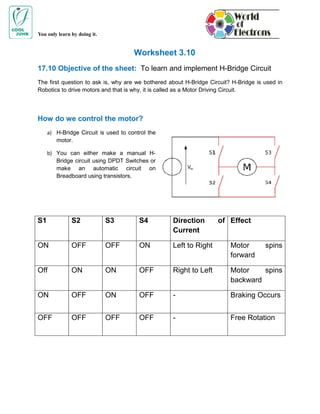
How do we control the motor?
a) H-Bridge Circuit is used to control the
motor.
b) You can either make a manual H-
Bridge circuit using DPDT Switches or
make an automatic circuit on
Breadboard using transistors.
S1 S2 S3 S4 Direction of Effect
Current
ON OFF OFF ON Left to Right Motor spins
forward
Off ON ON OFF Right to Left Motor spins
backward
ON OFF ON OFF - Braking Occurs
OFF OFF OFF OFF - Free Rotation
2. You only learn by doing it.
H-Bridge using transistors
Implement the following circuit on the project board. It is quite a complicated circuit. Refer
“Experiment Manual” for instructions.
Case 1: R2 should be grounded and R3 is given Vcc. No supply is given to R4 and R1.
Case 2: R1 should be grounded and R4 is given Vcc. No supply is given to R3 and R2.
3. You only learn by doing it.
Image Source: Robot Room
An H-Bridge Circuit is a simple arrangement of 4 transistors in such a way that allows for full
control over a DC motor. Observations:
a) Q2 and Q4: Q2 and Q4 are PNP Transistors. You will notice that emitter of both these
transistors is given positive voltage or Vcc. Hence, Q2 and Q4 provide positive supply to the
motors.
b) Q3 and Q1: Q3 and Q1 are NPN Transistors. You will notice that emitter of both these
transistors is grounded (negative supply). Hence, they connect motor to the ground.
c) R1 and R4: R1 and R4 are both 1K ohm resistors. They prevent too much current to pass
through the base of the Q1 and Q4 transistors. The value 1K is chosen in such a way that
Q1 and Q4 will be fully on or reach saturation stage. If we chose a lesser value than 1K
ohm, it will prevent the loss of power; however the motor will receive very less current. If we
chose a bigger value than 1K, it would waste more power.
4. You only learn by doing it.
d) D1 and D4: If motor stops in between or is about to stop, it may produce back emf (reverse
voltage) that can damage a transistor. So, diodes are used to dispersed or return energy
from the motor to the battery.
How H-Bridge Works
Just Remember this:
a) In a NPN Transistor, if base is given Vcc through a resistor and emitter is grounded, the
transistor will be on and is in saturation stage. However, when no supply is given to the
base, the transistor is off. You can connect one end of the motor to the collector end.
The motor terminal will receive negative supply from the transistor.
b) In a PNP Transistor, if base is grounded through a resistor and emitter is given Vcc, the
transistor will be on. When base is given Vcc, the transistor shall be in off state. You
can connect on end of the motor to the collector end. The motor terminal will receive
positive supply from the transistor.
c) Q1 and Q3 are on if R1 and R3 are given Vcc.
d) Q1 and Q3 are off if R1 and R3 are either grounded or given no supply
e) Q2 and Q4 are on if R2 and R4 are grounded.
f) Q2 and Q4 are off if R2 and R4 are given Vcc.
g) Study the following table
Q1 Q2 Q3 Q4 Result
Off On On Off Motor spins clockwise
On Off Off On Motor spins anti-clockwise
Off Off On On Motor breaks
Off Off Off Off Free Rotation