Uart 16550
•Als PPT, PDF herunterladen•
6 gefällt mir•7,224 views

The 16550 UART allows for asynchronous serial communication up to 1.5Mbps. It contains independent transmitter and receiver sections that allow for simplex, half-duplex, and full-duplex communication modes. The UART uses a programmable baud rate generator and 16-byte FIFO buffers to interface with processors. It is commonly used to control serial ports on PCs using two I/O address ranges. Programming involves initializing the line control register and baud rate generator, then performing the actual communication by reading and writing data using the FIFO and line status registers.

Empfohlen
Weitere ähnliche Inhalte
Was ist angesagt?
Was ist angesagt? (20)
Andere mochten auch
Ähnlich wie Uart 16550
Ähnlich wie Uart 16550 (20)
Kürzlich hochgeladen
Kürzlich hochgeladen (20)
Uart 16550
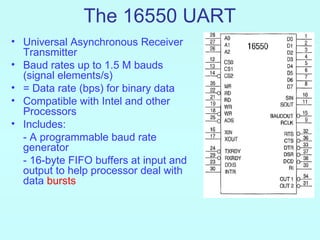
- 1. The 16550 UART • Universal Asynchronous Receiver Transmitter • Baud rates up to 1.5 M bauds (signal elements/s) • = Data rate (bps) for binary data • Compatible with Intel and other Processors • Includes: - A programmable baud rate generator - 16-byte FIFO buffers at input and output to help processor deal with data bursts
- 2. Asynchronous Serial Data Communication • Data sent asynchronously using the format illustrated below • We often use one start bit and one stop bit to frame the data, which is usually 8-data bits with or without parity Usually a byte of data
- 3. The 16550 UART: Functional Description • Totally independent Transmitter (TX) and Receiver (RX) Sections • This allows communication in the following modes: - Simplex: Only TX or RX is used 40 pin DIP (one direction all the time) - Half Duplex: TX then RX (two directions at different times) - Full Duplex: TX and RX simultaneously (two directions at the same time) • Can control a modem using six signals, e.g. #DSR (Data Set Ready) input, #DTR (Data Terminal Ready) output…. Here the UART is the data terminal and modem is the dataset.
- 4. The 16550 UART: Typical Configuration Serial to Parallel Or Parallel to Serial Converters Control µP 16-byte FIFO Input Buffer PS SIN Receiver UART Serial 16-byte FIFO Output Buffer PS Transmitter Comm. SOUT Link Data DMA Data Transfers: Memory UART Directly Without going through the µP Memory
- 5. The 16550 UART: Pin Assignments 3 I/O Address bits from Processor (Table 11-5) Chip Select Inputs Data bus to Processor (Multiple I/Ps) Master Reset (tie to µP Reset I/P) 40 pin DIP Read & Write Control inputs Serial data INput from RX from µP Serial data OUTput to TX (with complements for versatility Baud rate Clock output Address Strobe (not needed with Intels) Receiver Clock input Crystal or External Clock Input Modem Interface: TX ready for data. Put data into Inputs & Outputs UART by DMA Interrupt Processor User defined outputs RX ready with data. Take data from UART by DMA
- 6. UARTs in the PC • Used to control the COM ports of the PC - UART at I/O address 3F8-3FF: COM Port 0 - UART at I/O address 2F8-2FF: COM Port 2
- 7. Programming the UART Two Stages: a. Initialization Dialog: (Setup) - Follows RESET - Has two steps: 1. Program the line control register (Set asynchronous transmission parameters: # of stop, data, and parity bits, etc.) 2. Program the baud rate generator for the required baud rate b. Operation Dialog: (Actual Communication)
- 8. The 8 I/O Byte Locations on the UART A2 A1 A0 Function 0 0 0 Receiver buffer (read data from RX) and transmitter holding (write data to TX). Also write LS byte of baud rate divisor 0 0 1 Interrupt enable. Also write MS byte of baud rate divisor 0 1 0 Interrupt identification (read) and FIFO control Register (write) - Used for operation dialog programming 0 1 1 Line control Register (Write into the line control register to program asynchronous communication at initialization) 1 0 0 Modem control 1 0 1 Line status LSTAT (Read the line status register to see if TX or RX are ready and to check for errors ) 1 1 0 Modem status 1 1 1 Scratch
- 9. 1. Programming the Line Control Register a. Initialization I/O Address: A2 A1 A0 = 011 Dialog Programming Parity Control DL bit must be set See next slide Data Length = 5 bits before you can load the divisor Data Length > 5 bits for the baud generator See Table on next slide A break is a minimum of 2 frames of 0’s To allow programming The baud rate generator
- 10. The 3 Parity Control Bits in the Line Control Register ST P PE Function 0 0 0 No parity 0 0 1 Odd parity 0 1 0 No parity 0 1 1 Even parity 1 0 0 Undefined 1 0 1 Send/receive 1 (send 1 in place of the parity bit) 1 1 0 Undefined 1 1 1 Send/receive 0 (send 0 in place of the parity bit)
- 11. 2. Programming the Baud rate Generator • Baud rate is programmed by loading a 16-bit Baud Rate Divisor Value divisor for the crystal oscillator (or external input) 110 10,473 frequency into the I/O port addresses: 300 3840 {A2 A1 A0} = 000: LS Byte of divisor 1200 920 {A2 A1 A0} = 001: MS Byte of divisor 2400 480 4800 240 • Divisor value is determined by the Oscillator frequency and the baud rate required: 9600 120 19,200 60 Divisor = Oscillator frequency / (16 * Baud rate) 38,400 30 57,600 20 Table shows divisor values required for various 115,200 10 baud rates for osc frequency = 18.432 MHz
- 12. (Active Low)
- 13. ;Initialization dialog for Figure 11-45 ;Baud rate 9600, 7 bit data, odd parity, 1 stop bit LINE EQU 0F3H ; A2 A1 A0 = 011 for the Line Control Register LSB EQU 0F0H ; A2 A1 A0 = 000 for LSB of divisor MSB EQU 0F1H ; A2 A1 A0 = 001 for MSB of divisor FIFO EQU 0F2H ; A2 A1 A0 = 010 for the FIFO Control Register INIT PROC NEAR MOV AL,10001010B OUT LINE,AL ; Enable Baud rate programming See slide 108 ; program Baud 9600 ; Divisor = 120d (see Table on slide 110) MOV AL,120 ; LSB of divisor OUT LSB,AL MOV AL,0 ; MS Byte of divisor OUT MSB,AL MOV AL,00001010B ;program 7 bit data, odd Must write this OUT LINE,AL ;parity, 1 stop bit into FIFO Register ;(& disable baud rate programming?) to enable communication and operation dialog MOV AL,00000111B ;enable transmitter and receiver programming OUT FIFO,AL ;by writing into the FIFO control Reg. RET INIT ENDP
- 14. 16550 FIFO Control Register (Write) I/O Address: A2 A1 A0 = 010 Required to enable 1 1 1 actual communication (Operation Dialog)
- 15. b. Operation Dialog 16550 Line Status Register (LSTAT) Programming I/O Address: A2 A1 A0 = 101 Before reading data from receiver, ensure RX has data [DR (bit 1) = 1] Error status bits Any being 1 indicates An error Before writing data for transmission, Ensure TX is ready to take it [TH (bit 5) = 1]
- 16. ;A procedure that transmits the byte in AH serially ;via the 16650 UART LSTAT EQU 0F5H ; The Line status register (LSTAT) (A2 A1 A0 = 101) DATA EQU 0F0H ; TX/RX Data Register at (A2 A1 A0 = 000) SEND PROC NEAR USES AX .REPEAT ;test the TH bit (bit 5) in to see if TX is available IN AL,LSTAT TEST AL,20H ;20H is the mask for the TH bit .UNTIL !ZERO? MOV AL,AH OUT DATA,AL ;send data to TX (LSTAT) RET SEND ENDP
- 17. ; Procedure receives byte from UART into AL if no comm. error ; If error detected, it load Al with ‘?’ as an alert LSTAT EQU 0F5H ; The Line status register (LSTAT) (A2 A1 A0 = 101) DATA EQU 0F0H ; TX/RX Data Register at (A2 A1 A0 = 000) REVC PROC NEAR .REPEAT IN AL,LSTAT ;test DR bit TEST AL,1 .UNTIL !ZERO? TEST AL,0EH ;test for any error .IF ZERO? ;no error IN AL,DATA ;Read RX Data Register into AL .ELSE ;any error MOV AL,’?’ ;Put “?” in AL to indicate error .ENDIF RET RECV ENDP