The TIW Series paddle wheel flow meter has a lifetime warranty and provides highly accurate flow measurement from 0.3 to 33 ft/s. It has a digital pulse output and can be installed using various ANSI and DIN fittings to measure flow in pipes from 1/2 to 24 inches. The flow meter is available in PVC, PP, and PVDF materials to be chemically resistant for use in many liquid processes.
Boost Fertility New Invention Ups Success Rates.pdf
TIW Series Paddle Wheel Flow Meter.pdf
1. TIW SERIES
Paddle Wheel Flow Meter
**https://www.grc.nasa.gov/www/k-12/airplane/shaped.html
Flying Lead | Hirschmann QDIN Connection
Flow Range | 0.3 to 33 ft/s
Eprom Memory | Totalizer Value Will Not Be Lost
Retrofits into Signet® Type Fittings
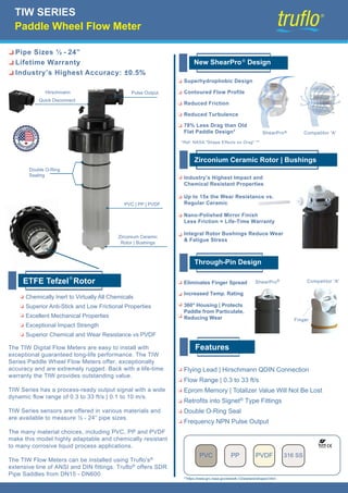
Double O-Ring Seal
Frequency NPN Pulse Output
PVC PP PVDF
ShearPro Competitor 'A'
*Ref: NASA "Shape Effects on Drag" **
Industry’s Highest Impact and
Chemical Resistant Properties
Up to 15x the Wear Resistance vs.
Regular Ceramic
Nano-Polished Mirror Finish
Less Friction = Life-Time Warranty
Integral Rotor Bushings Reduce Wear
& Fatigue Stress
Eliminates Finger Spread
Increased Temp. Rating
360° Housing | Protects
Paddle from Particulate,
Reducing Wear
Superhydrophobic Design
Contoured Flow Profile
Reduced Friction
Reduced Turbulence
78% Less Drag than Old
Flat Paddle Design* ®
Competitor 'A'
ShearPro®
New ShearPro Design
®
Zirconium Ceramic Rotor | Bushings
Through-Pin Design
Features
Chemically Inert to Virtually All Chemicals
Superior Anti-Stick and Low Frictional Properties
Excellent Mechanical Properties
Exceptional Impact Strength
Superior Chemical and Wear Resistance vs PVDF
ETFE T ®
efzel Rotor
Finger
The TIW Digital Flow Meters are easy to install with
exceptional guaranteed long-life performance. The TIW
Series Paddle Wheel Flow Meters offer, exceptionally
accuracy and are extremely rugged. Back with a life-time
warranty the TIW provides outstanding value.
TIW Series has a process-ready output signal with a wide
dynamic flow range of 0.3 to 33 ft/s | 0.1 to 10 m/s.
TIW Series sensors are offered in various materials and
are available to measure ½ - 24” pipe sizes.
The many material choices, including PVC, PP and PVDF
make this model highly adaptable and chemically resistant
to many corrosive liquid process applications.
The TIW Flow Meters can be installed using Truflo's®
extensive line of ANSI and DIN fittings. Truflo® offers SDR
Pipe Saddles from DN15 - DN600
Pipe Sizes ½ - 24”
Lifetime Warranty
Industry’s Highest Accuracy: ±0.5%
Double O-Ring
Sealing
PVC | PP | PVDF
Zirconium Ceramic
Rotor | Bushings
Hirschmann
Quick Disconnect
Pulse Output
316 SS
2. TIW SERIES
Paddle Wheel Flow Meter
See Temperature and Pressure Graphs for more information
Note: The Pressure/Temperature graphs are specifically for the Truflo® Flow Sensors.
During system design the specifications of all components must be considered.
Body Material
P - PVC
PP - PP
PF - PVDF
DIN Connection (Std)
Suffix 'F' for Lead Wire | 3m
S - ½"- 4" Pipe
L - 6"- 24" Pipe
FKM (Std)
Suffix 'E' For EPDM
Wire Connection Body Length Seals
PF S
TIW
Model Selection
Temperature | Pressure Graphs | Non-Shock
General
Wetted Materials
Electrical
Max. Temperature/Pressure Rating - Standard and Integral Sensor | Non-Shock
Operating Temperature
Operating Range
Pipe Size Range
Linearity
Repeatability
Standards and Approvals
0.3 to 33 ft/s
½ to 24"
0.1 to 10 m/s
DN15 to DN600
±0.5% of F.S @ 25°C | 77°F
±0.5% of F.S @ 25°C | 77°F
Sensor Body
O-Rings
Rotor Pin | Bushings
Paddle | Rotor
PVC (Dark) | PP (Pigmented) | PVDF (Natural)
FKM | EPDM* | FFKM*
Zirconium Ceramic | ZrO2
ETFE Tefzel
180 psi @ 68°F
40 psi @ 140°F
180 psi @ 68°F
40 psi @ 190°F
200 psi @ 68°F
40 psi @ 240°F
12.5 bar @ 20°C
2.7 bar @ 60°C
12.5 bar @ 20°C
2.7 bar @ 88°C
14 bar @ 20°C
2.7 bar @ 115°C
PVC
PP
PVDF
32°F to 140°F
-4°F to 190°F
-40°F to 240°F
0°C to 60°C
-20°C to 88°C
-40°C to 115°C
CE | FCC
RoHS Compliant
PVC
PP
PVDF
Frequency Pulse
Supply Voltage
Supply Current
49 Hz per m/s nominal
5 to 24 VDC ±10% regulated
<1.5 mA @ 3.3 to 6 VDC
15 Hz per ft/s nominal
<20 mA @ 6 to 24 VDC
®
68
0
20
40
60
80
100
120
140
160
180
200
220
104 140 175 212 248
20 40 60 80 100 120
0
1.4
2.8
4.1
5.5
6.9
8.3
9.7
11.0
12.4
13.8
15.2
°F
°C
bar psi
PVC PP PVDF
Optional*
S S