Digital Detectors for Industrial Applications-Nityanand Gopalika
•
5 gefällt mir•4,313 views

A case study on digital detectors performance study

Empfohlen
Weitere ähnliche Inhalte
Was ist angesagt?
Was ist angesagt? (20)
Ähnlich wie Digital Detectors for Industrial Applications-Nityanand Gopalika
Ähnlich wie Digital Detectors for Industrial Applications-Nityanand Gopalika (20)
Kürzlich hochgeladen
Kürzlich hochgeladen (20)
Digital Detectors for Industrial Applications-Nityanand Gopalika
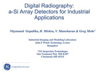
- 1. Digital Radiography: a-Si Array Detectors for Industrial Applications Nityanand Gopalika, D. Mishra, V. Manoharan & Greg Mohr* Industrial Imaging and Modeling Laboratory John F Welch Technology Center Bangalore *GE Inspection Technologies One Neumann Way MD K207 Cincinnati, OH 45215
- 2. Presentation Outline: • • • • • Technology Development Benefits of Digital Radiography Quantifying Image Quality Image Quality Metric for Digital Systems Comparison of Imaging Devices: CCD, CMOS and a-Si • Performance Study of Flat Panels
- 3. Technology Development NDT World Film radiography Productivity Resolution Image intensifiers Computed radiography Cost Size CCD technology Direct digital radiography Evolution of Direct Digital X-ray Detectors 3/ Industrial Imaging and Modeling Laboratory
- 4. Benefits of Digital Radiography Productivity • Faster response • Elimination of chemical processing • Automated inspection • Elimination of retakes Cost • Elimination film and consumables • ROI in two to three years Quality • Image processing and analysis • Reduces operators fatigue • Consistency Advanced Application • Volumetric CT for High Throughput Productivity and cost benefits 4/ Industrial Imaging and Modeling Laboratory
- 5. Quantifying Image Quality Increasing Contrast What is a good Physical Measure of Image Quality? Contrast-to-Noise Ratio Perceived Image Quality Decreasing Noise Measure of Image Quality 5/ Industrial Imaging and Modeling Laboratory
- 6. Image Quality Metric for Digital Systems MTF: Same Response to Signal and Noise 6/ Industrial Imaging and Modeling Laboratory
- 7. Image Quality Metric for Digital Systems MTF Limitations Contrast Limiting Spatial Resolution (LSR), MTF measured at high contrast • bar patterns » 100% input contrast MTF indicates fraction of signal that will be seen in image. Noise MTF measured under noiseless conditions. MTF transfers noise in addition to signal. Image noise can interfere with object detectability. Higher MTF Does Not Mean Better Imaging System 7/ Industrial Imaging and Modeling Laboratory
- 8. Image Quality Metric for Digital Systems Low Middle MTF: High SNR = 1 MTF High Middle Low Higher limiting resolution of smaller pixels may not provide better detectability in noisy images. High MTF; But Poor Performance 8/ Industrial Imaging and Modeling Laboratory
- 9. Image Quality Metric for Digital Systems • Quantum and electronic noise are unavoidable in digital imaging chain. • SNR can vary widely across systems • High SNR is key to better inspection power • To increase SNR often the only way is to increase radiation dose, unacceptable trade-off • Achieving high SNR at lower dose: better imaging system Traditional gauge used for quantifying image quality cannot be used as a stand alone metric. MTF is One Metric; But Not Enough 9/ Industrial Imaging and Modeling Laboratory
- 10. Image Quality Metric for Digital Systems DQE: Detective Quantum Efficiency DQE = SNR2 at detector output SNR2 at detector input SNR = signal-to-noise ratio Measure of SNR transmittance 10 / Industrial Imaging and Modeling Laboratory
- 11. Image Quality Metric for Digital Systems Input SNR2 proportional to radiation dose DQE • • α Image Quality Input Radiation Dose Traditional measures such as MTF, LSR are not sufficient to characterize detector performance Noise is a limiting factor for detectability, image processing, and advanced applications Doubling DQE means: • • Same output SNR (“image quality”) at half the dose 40% improvement in SNR at same dose Less Dose and Better Image 11 / Industrial Imaging and Modeling Laboratory
- 12. Image Quality Metric for Digital Systems “Object” SNR = 5 “Improved” DQE = 0.5 SNR = 3.5 “Standard” DQE = 0.25 SNR = 2.5 High DQE at Lower Dose 12 / Industrial Imaging and Modeling Laboratory
- 13. Image Quality Metric for Digital Systems Film GE Detector High DQE Better Detectability 13 / Industrial Imaging and Modeling Laboratory
- 14. Image Quality Metric for Digital Systems Detector Design Keeping DQE in Mind 14 / Industrial Imaging and Modeling Laboratory
- 15. Detector Design for High DQE The Detector Properties Pixel Size Sampling, Fill Factor, Aliasing Scintillator/ Coupling CsI, Lanex, Se lens/Direct Measurements and Requirements MTF High Resolution (for small object detection) Signal (S) Efficient X-Ray Conversion (for minimum exposure) Photodetector aSi, CCD, CMOS Readout One Image Quality Measure DQE 1 S 2 ⋅ MTF 2 DQE = Q NPS Noise (NPS) Low Noise (for clear visualization) Electronic Noise 15 / Industrial Imaging and Modeling Laboratory
- 16. Flat Panel Technology Direct Conversion (Se) Indirect Conversion (CsI) Photons Photons Cesium Iodide (CsI) Selenium Light Amorphous Silicon Panel Electrons Read Out Electronics Digital Data Electrons Read Out Electronics Digital Data Flat Panel Technology Variation 16 / Industrial Imaging and Modeling Laboratory
- 17. CsI vs. Se Cesium Iodide Selenium • • • • • Very high DQE; potential for high image quality at low dose Fluoro capable Advanced application capable Mature technology: 25-year history with Image Intensifiers • • • Direct conversion of X-Ray into electrical signals Currently not capable of fluoro Low X-Ray absorption High sensitivity to temperature Again Keep DQE in Mind!! 17 / Industrial Imaging and Modeling Laboratory
- 18. Point Spread Function for Different Detector Types Electrons Image Intensifiers CSI Flat panels Se Flat panels MTF is One Part of the Story, DQE is the Other BIG Part 18 / Industrial Imaging and Modeling Laboratory
- 19. CCD Technology Photons Scintillator Light Fiber Optic Taper CCD Electrons CCD Amorphous Silicon • • • • • Potentially high image quality at low dose (high DQE) Active Research on New Applications Designed for X-Ray from the start Compact packaging Very high development cost • • • • • CCDs are easily available Low development costs “Transition” technology to flat panel High CCD cost Tiling and design complexity 19 / Industrial Imaging and Modeling Laboratory
- 20. Silicon Imaging Devices, CCD, CMOS & a-Si Imager Dimensions • • • CCDs: CMOS: a-Si: 10 – 60-mm on a side 50-mm on a side 200 – 410-mm on a side Size governed by silicon process • CCDs and CMOS – 6” wafers • Multiple chips/wafer – yield • a-Si – Large area deposition/glass Pixel Dimensions • CCDs: 9 – 25 microns • CMOS: 40 – 50 microns • a-Si: 100 – 400 microns • Pixel size governed by architecture All will convert visible energies into an electronic charge 20 / Industrial Imaging and Modeling Laboratory
- 21. Silicon Imaging Devices, CCD, CMOS & a-Si Coupling device or Method Silicon Device Phosphor or Photoconductor Fiber optic coupler Requires 10X more Exposure CCD or CMOS Requires 100X more Exposure Lens Fiber optic scintillator and/or Shielding phosphor Glass Cooled CCD Camera 21 / Industrial Imaging and Modeling Laboratory
- 22. GE Digital X-Ray Detectors 3 Types of GE Digital X-Ray Panels All feature high efficiency & fast 14-bit readout Highest resolution (DXR-500) • 7” x 9” (19 cm x 23 cm) @ 100 micron • Over 20% MTF at 5 lp/mm Highest efficiency (DXR-250) • 16” x 16” (41 cm x 41 cm) @ 200 micron Fastest Imaging (DXR-250RT) • Up to 30 Hz • 8” x 8” (20 cm x 20 cm) @ 200 micron Panels Optimized for Different Applications 22 / Industrial Imaging and Modeling Laboratory
- 23. Performance Study: Radiation Exposure DXR-500 DR system Signal(ADC) 14000 12000 10000 8000 6000 4000 2000 0 0 5 10 15 20 25 30 35 Relative exposure Comparative study Industrial X-ray film Characteristics DXR-500 Digital Detector ( Medium speed) In the order of few mR to get 1.3 R to get Optical Speed signal level of 12000 density of 2 Useful minimum to Useful minimum to Dynamic range maximum exposure maximum exposure ratio 12 ratio 2 Typical Exposure ratio requirements Material Ti Steel X-ray tube Lattitude potential 3 to 20 mm 160 kV 1 to 10 mm 160 kV Subject contrast 12.7 7.28 Useful exposure range Min and Max exp ratio 2 Productivity: • High Speed (mR vs. R) • Minimized Rework • High Latitude Coverage Advantages • Less radiation field • Micro focus (Faster response enables high definition radiography) Detector Characteristics Suitable for Industrial Applications 23 / Industrial Imaging and Modeling Laboratory
- 24. Dynamic range Ti step wedge image 2 –20 mm 1 • • 2 • 3 • • 2& 3 window level adjusted High latitude coverage ~ 10 times > imageintensifier No blooming or saturation Window leveling No Lead masking Wide dynamic range enables- high latitude imaging 24 / Industrial Imaging and Modeling Laboratory
- 25. Artifacts Source:GE Health care Source:GE Health care Flat panel- no distortion Image Intensifier- distortion Flat panel > No distortion XII > No blooming > Uniform sensitivity over entire area > Brightness uniformity Source:GE Health care Brightness uniformity 25 / Industrial Imaging and Modeling Laboratory
- 26. Performance study-Spatial resolution FS = 1.8 mm FS = 0.4 mm Observation: • System can be designed to match with film MTF. • Digital detector with mini/micro focal tube outperforms film radiography with large focal spots. • DQE of DXR-500 is comparatively good. FS = 1.8mm System Design for Meeting Requirements FS = 0.4 mm 26 / Industrial Imaging and Modeling Laboratory
- 27. Detective quantum efficiency Source: GE healthcare DQE comparison- XII vs. DR Better defect detectability in useful spatial resolution range 27 / Industrial Imaging and Modeling Laboratory
- 28. Performance study-Noise response • Poisson distributed noise • Noise Quantum limited • Averaging of frames reduces noise Effect of no. of frames 5 frames Effect of no. of X-ray photons 1 mAs 10 frames 20 frames 5 mAs Quantum Limited Noise Performance 28 / Industrial Imaging and Modeling Laboratory
- 29. Performance study-IQI sensitivity Mat. – Ti Thick. – 25mm KVp – 120 mAs – 1.0 FS – 0.4 mm Mat. – Ti Thick. – 10mm KVp – 120 mAs – 1.0 FS – 0.4 mm Mat. – Al Thick. – 40 mm KVp – 120 mAs – 1.0 FS – 0.4 mm Mat. – SS Thick. – 10mm KVp– 140 mAs – 1.0 FS – 0.4 mm 2-1T sensitivity over range of thickness 29 / Industrial Imaging and Modeling Laboratory
- 30. Performance study-Imaging 2-2T Porosity Sensitivity Lack of penetration KVp – 125 mAs – 1.0 FS – 0.4 mm Mat. – CSI KVp – 125 Mat. – CS mAs – 1.0 FS – 0.4 mm 30 Range of applications with 2-1T sensitivity Imaging and Modeling Laboratory/ Industrial
- 31. Performance study-Imaging Object – IC KVp – 70 mAs – .5 FS – 10 microns Mag. – 50X Object – IC KVp – 70 mAs – .5 FS – 10 microns Mag. – 50X Object –ceramics KVp – 70 mAs – .5 FS – 10 microns Mag. – 50X Enable high definition radiography 31 / Industrial Imaging and Modeling Laboratory
- 32. Welding defects-Lack of penetration and spatter Material: CS Plate, 12 mm thk SW SI – Offset FS-0.4 mm SDD-700 mm KVp: 130, 2 mAs Filter: Cu –0.4 mm 32 / Industrial Imaging and Modeling Laboratory
- 33. Summary • System can be designed to meet image quality requirements • • Quantum limited noise performance Faster response and wide dynamic range • Real time (fluoro) • Range of applications with 2-1T sensitivity • • Enables high definition radiography Advanced image processing for image optimization 33 / Industrial Imaging and Modeling Laboratory