Angle and ramus fracture, simple
•
12 gefällt mir•1,889 views

Repositioning and fixation of simple, non displaced mandibular angle fractures by means of minimum exposure of the fracture site and fixation by wiring osteosynthesis.

Empfohlen
Weitere ähnliche Inhalte
Was ist angesagt?
Was ist angesagt? (20)
Andere mochten auch
Andere mochten auch (20)
Ähnlich wie Angle and ramus fracture, simple
Ähnlich wie Angle and ramus fracture, simple (20)
Kürzlich hochgeladen
Kürzlich hochgeladen (20)
Angle and ramus fracture, simple
- 1. Angle and ramus fracture, simple wire fixation
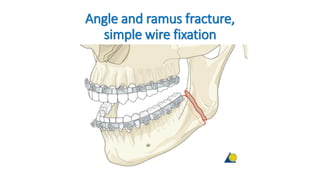
- 2. Intraosseous wire fixation of angle fractures is a nonrigid technique that requires 5-6 weeks of postoperative MMF. It is indicated when plate/screw fixation is not available and the mandibular ramus is likely to rotate upwards and forwards because of the attached muscles. In such instances, closed reduction may not be effective. The intraosseous wire will help to prevent rotation of the mandibular ramus.
- 3. The intraosseous wire must be placed to resist the upward and forward direction in which the ramus will tend to rotate. Therefore, it is prudent to place the hole through the proximal fragment superiorly to the hole in the distal fragment. It is not necessary for the intraosseous wire to engage both buccal and lingual cortices on each side of the fracture. It is only necessary to engage the buccal cortices with the wire. Because this is a nonrigid technique, 5-6 weeks of MMF must be applied after surgery. Principles
- 4. Arch bars are applied to the teeth and MMF is secured. The patient is monitored for positional changes of the mandibular ramus using x-rays. At 6 weeks MMF is released and fracture stability determined by manipulation. The patient is placed on a soft diet and if the occlusion maintains for a two-week period, the arch bars may be removed.
- 5. Exposure of fracture The fracture should be exposed and any extractions determined necessary be performed. Open reduction in dentate patients usually begins with fixation of the occlusion. However, MMF is not desirable when using intraosseous wire fixation until the wire is to be tightened. It is easier to drill the holes in the bone and to pass the wire while the patient’s jaws are open.
- 6. The “Vestibular” incision or “Ward modified” incision can be used for standard fracture fixation techniques. In order to more easily approach the operative field it is preferred to extend the mesial cutting into the vestibule with a release incision. The region of the mandibular angle & ramus can best be exposed by extending the standard vestibular incision in a superior direction up the ascending ramus. The incision can be altered depending on the area of the ramus/mandibular angle process that needs exposure and treatment. Intraoral approach to the mandibular angle & ramus Principles Vestibular incisions A) Vestibular incision B) “Ward” modified incision Oral contamination is not a contraindication for an intraoral incision.
- 7. Sensory buccal nerve The sensory buccal nerve crosses the upper anterior rim of the mandibular ascending ramus in the region of the coronoid notch. It is usually below the mucosa running above the temporalis muscle fibers. When the posterior vestibular incision is carried sharply along the bony rim, the buccal nerve is at risk of transsection resulting in numbness in the buccal mucosal region. Therefore, to protect the nerve, the posterior incision is to be extended bluntly as soon as the lower coronoid notch is reached.
- 9. Sensory buccal nerve Mental nerve The mental nerve is a branch of the fifth cranial nerve (trigeminal nerve). This nerve provides sensation to the anterior mandibular vestibule, lip and chin. When the incisionis extended posterior to the canine teeth, the mental nerve can be damaged. Keep the incision superior to the mental nerve in the body region. Particularly in the extended intraoral approach, care must be taken to protect the mental nerve in the anterior body region.
- 10. Mental nerve
- 11. photography of anatomical preparation photography of anatomical preparation showing
- 13. The bony attachments of the buccinator muscle run a course below the mucogingival junction opposite to the molars and along the oblique line ascending as the anterolateral rim of the ascending ramus. The attachments extend back into the pterygomandibular raphe. The buccinator is innervated by the buccal branch of the facial nerve. The muscle belongs to the mimetic muscle system and has a unique functional structure allowing for movement comparable to peristaltic motion. Its detachment can result in an impaired bolus transport. Reminder: The buccinator muscle belongs to the mimic muscle system and has a unique functional structure allowing for a movement comparable to a peristaltic motion. The deep fibers run in parallel bundles from the modiolus to the pterygomandibular raphe at the level of the occlusal plane (intercalar region) and account for the buccinator mechanism building up a ridge towards the occlusal plane. Its detachment can result in an impaired bolus transport out of the buccal space which can be annoying for the patient. The buccinator is innervated by the motor buccal branch of the facial nerve.
- 14. The lateral mucogingival vestibular incision transects the lower attachment of the buccinator muscle. Stripping the mucoperiosteal flap laterally dislocates the lower border of the muscle. To reattach the muscle, the sutures for wound closure in the lateral vestibular should not only be superficial. The suture should catch all layers (mucosa and muscle) as a safeguard for muscle reattachment. The buccinator is innervated by the motor buccal branch of the facial nerve.
- 15. The buccinator muscle belongs to the mimic muscle system and has a unique functional structure allowing for a movement comparable to a peristaltic motion. The deep fibers run in parallel bundles from the modiolus to the pterygomandibular raphe at the level of the occlusal plane (intercalar region) and account for the buccinator mechanism building up a ridge towards the occlusal plane. Its detachment can result in an impaired bolus transport out of the buccal space which is troublesome for the patient. Reminder:
- 17. Vestibular incision Unless contraindicated, infiltrate the area with a local anesthetic containing a vasoconstrictor. Make an incision through the mucosa in the vestibule approximately 5 mm away from the attached gingiva (in the mucogingival junction),extending up the external oblique ridge.
- 18. Step 1. Injection of Vasoconstrictor The oral mucosa, submucosa, and facial muscles are lushly vascularized. Submucosal injection of a vasoconstrictor can remarkably reduce the amount of hemorrhage during incision and dissection. Step 2. Incsion In the body and posterior portion of the mandible, the incision is placed 3 to 5 mm inferior to the mucogingival junction (see Fig. 8.10). Leaving unattached mucosa on the alveolus facilitates closure. The posterior extent of the incision is made over the external oblique ridge, traversing mucosa, submucosa, buccinator muscle, buccopharyngeal fascia, and periosteum (Fig. 8.5A).
- 19. Photograph showing incision location when vestibular approach is used to expose the ramus and posterior body of the mandible. Note that there is some unattached mucosa remaining along the attached gingiva to facilitate closure. The incision is usually no more superior than the occlusal plane of the mandibular teeth to help prevent herniation of the buccal fat pad into the surgical field, a nuisance during surgery. The buccal portion of the buccal fat pad is usually not more inferior than the level of the occlusal plane The incision is usually no more superior than the occlusal plane of the mandibular teeth to help prevent herniation of the buccal fat pad into the surgical field, a nuisance during surgery. The buccal portion of the buccal fat pad is usually not more inferior than the level of the occlusal plane (Fig. 8.4). Placement of the incision at this level also may spare the buccal artery and nerve, although their damage is more a nuisance than a clinical problem. If the buccal artery is severed, bleeding is easily controlled by coagulation.
- 20. The buccal fat pad consists of a main body and four extensions: buccal, pterygoid, pterygomandibular, and temporal. The body is centrally positioned. The buccal extension lies superficially within the cheek, while the pterygoid, pterygomandibular, and temporal extensions are more deeply situated. The buccal extension is the most superficial segment of the fat pad and imparts fullness to the cheek. It enters the cheek below the parotid duct and extends along the anterior border of the masseter as it descends into the mandibular retromolar region. It overlies the main portion of the buccinator muscle as it crosses the cheek. In the cheek, the fat pad is anterior to the ramus. Its caudal extension intraorally is on a plane tangential with the occlusal surface of the mandibular third molar (see Fig. 8.4). Its anterior limit is marked by the facial vessels, which are in the same plane as the buccal fat pad. The parotid duct lies superficial to the fat pad and then penetrates the fat pad and buccinator to enter the oral cavity opposite the second molar. The buccal extension of the fat pad is limited by the masseteric fascia. A deep extension of the masseteric fascia blends with the fascia along the lateral surface of the buccinator. This fascial layer lines the deep surface of the buccal fat that is in contact with the buccinator.
- 21. The buccal fat pad first described by Marie Bichat in 1801 is located in an extended three-dimensional compartment with its main mass or cheek portion overlying the posterolateral aspect of the buccinator muscle and the maxillary tuberosity, which is partly covered by the anterior border of the masseter muscle. The major processes of the fat pad stretch into deep temporal, pterygomaxillary and pterygoid region. The fat is distinct from facial fat and similar to orbital fat in consistency and its globule-like structure, to which it connects through the infraorbital fissure. The facial vessels run along the anterior border of the cheek portion. The fascial layers (capsule) enveloping the buccal fat pad on the medial surface next to the buccinator muscle are rarely ruptured in a subperiosteal dissection along the mandibular body and angle. However, when going up the ramus subsequent to a vertical division of the buccinator muscle anterior to the pterygomandibular raphe in order to reach beyond the coronoid notch the inner capsule of the fat pad can be breached leading to a herniation that will obstruct the vision in the surgical field.
- 22. Step 3. Subperiosteal Dissection of the Mandible Subperiosteal dissection of the mandibular body is relatively simple compared to that of the symphysis because there are fewer Sharpey fibers inserting into the bone. Dissection can then proceed posteriorly along the lateral surface of the mandibular body/ramus. The surgeon should stay within the periosteal envelope to prevent lacerating the facial vessels, which are just superficial to the periosteum (Fig. 8.2). Figure 8.2 Anatomic dissection of the mandibular body showing relation of facial vessels to bone. The only tissue between them is the periosteum.
- 23. Facial Vessels The facial artery and vein are usually not encountered during the mandibular vestibular approach unless dissection through the periosteum occurs in the region of the mandibular antegonial notch. The facial artery arises from the external carotid artery in the carotid triangle of the neck. At or close to its origin, it is crossed by the posterior belly of the digastric muscle, the stylohyoid muscles, and the hypoglossal nerve. In the submandibular triangle, the facial artery ascends deep to the submandibular gland, grooving its deep and superior aspect, and then passes superficially to reach the inferior border of the mandible. As the artery crosses the mandible at the anterior border of the masseter muscle, it is covered on its superficial surface by skin and platysma muscle, and its pulsations can be felt at this location.
- 24. Vessels The facial vessels cross the inferior border of the mandible at the level corresponding to the anterior border of the masseter muscle. The vessels are embedded in the lower extensions of the buccal fat pad.
- 25. Vessels Facial artery and vein
- 26. Facial artery and vein The artery is always located anterior to the vein. A periosteal layer separates the vascular bundle from the lateral bony surface of the mandible.
- 27. The facial vein is the drainage of the angular and ultimately labial vessels. It is usually located more posterior and superficial to the artery. Of surgical significance, however, is the fact that the facial artery and vein are close to the mandible in the region of the inferior border. The only structure that separates the vessels from the bone is the periosteum (see Fig. 8.2). Figure 8.2 Anatomic dissection of the mandibular body showing relation of facial vessels to bone. The only tissue between them is the periosteum.
- 28. Subperiosteal dissection of the ramus. Posteriorly, the incision leaves the crest at the second molar region and extends laterally to avoid the lingual nerve, which may be directly over the third molar area. Placing the incision over the ascending ramus helps to avoid the lingual nerve. Dissection can then proceed posteriorly along the lateral surface of the mandibular body/ramus. The surgeon should stay within the periosteal envelope to prevent lacerating the facial vessels, which are just superficial to the periosteum (Fig. 8.2).
- 29. Subperiosteal dissection along the anterior edge of the ascending ramus strips the buccinator attachments, allowing the muscle to retract upward, minimizing the chance of herniation of the buccal fat pad (Fig. 8.4). Temporalis muscle fibers may be stripped easily by inserting the sharp end of a periosteal elevator between the fibers and the bone as high on the coronoid process as possible, and stripping downward (see Fig. 8.13). A notched right-angle retractor(see Fig. 8.14) may be placed on the anterior border of the coronoid process to retract the mucosa, buccinator, and temporalis tendon superiorly during stripping. Stripping some of the tissue from the medial side of the ramus will widen the access. After stripping the upper one third of the coronoid process, a curved Kocher clamp can be used as a self-retaining retractor grasping the coronoid process. Figure 8.14 Notched right-angle retractor. The ‘‘V’’-shaped notch is positioned on the ascending ramus and the retractor is pulled superiorly to retract tissues.
- 30. While the buccal tissues are retracted laterally with a right- angle retractor, the masseter muscle is stripped from the lateral surface of the ramus (Fig. 8.13). Sweeping the periosteal elevator superoinferiorly strips the muscle cleanly from the bone. Although direct visualization may be poor, the posterior and inferior borders of the mandible are readily stripped of pterygomasseteric fibers using periosteal elevators, J- strippers, or both. Dissection can continue superiorly, exposing the condylar neck and the entire sigmoid notch. To maintain
- 31. exposure of the ramus, Bauer retractors (see Fig. 8.15) inserted into the sigmoid notch and/or under the inferior border are useful (see Fig. 8.16). The LaVasseur-Merrill retractor is another useful device that slides behind and clutches the posterior border of the mandible to hold the masseter in a lateral position. Figure 8.15 Bauer retractors. The flanges at right angle to the shaft are used to engage the sigmoid notch and/or inferior border of the mandible, allowing retraction of the masseter muscle. Figure 8.16 Exposure after insertion of Bauer retractors. Note the flange of one retractor is in the sigmoid notch and the flange of the other is under the inferior border of the mandible.
- 32. This clinical image shows the fracture exposed, reduced, and MMF secured.
- 33. The intraosseous wire must be placed to resist the upward and forward direction in which the ramus will tend to rotate. Therefore, it is prudent to place the hole through the proximal fragment superiorly to the hole in the distal fragment. It is not necessary for the intraosseous wire to engage both buccal and lingual cortices on each side of the fracture. It is only necessary to engage the buccal cortices with the wire. Because this is a nonrigid technique, 5–6 weeks of MMF must be applied after surgery.
- 34. A 1.5 mm hole is drilled through the buccal cortex of the distal fragment. A second hole, located more superiorly, is drilled through the buccal cortex of the proximal fragment. If the terminal molar is extracted as part of the procedure, the holes enter the socket. If no tooth is extracted, the holes enter the medullary space and exit into the fracture. The holes can be drilled with a drill inserted through the oral cavity or alternatively, a Steinmann pin can be inserted transcutaneously to drill the holes.
- 35. Applying internal wire fixation A 0.5 mm wire (24 gauge) is passed through the holes and preliminarily twisted together. Prior to final tightening of the wire, the patient must be placed into occlusion and secured with MMF. The intraosseous wire is then tightened, cut, and twisted down to the bone.
- 36. Case example Panoramic and PA x-rays show left simple angle fracture associated with ...
- 37. … an impacted third molar.
- 38. Because it is anticipated that the second molar might be removed in addition to the third molar the soft-tissue incision is made as demonstrated.
- 39. Subperiosteal dissection exposes the fracture and the impacted third molar.
- 40. The impacted third molar is being removed because it interfered with fracture reduction.
- 41. The second molar is also removed because there is a large bony defect along the posterior root.
- 42. After making two holes, the wire is then passed from the extraction site out the hole in the proximal fragment.
- 43. The wire is then preliminarily tightened. Prior to final tightening, the patient should be placed into MMF.
- 44. The wire has been tightened, cut, and bent down to lay against the bone.
- 45. To facilitate closure over the second molar extraction site, the flap is undermined with scissors.
- 46. Note that the flap has now been mobilized.
- 47. The flap has been closed over the extraction site.
- 48. MMF is secured and left in position for 5–6 weeks. Note this patient’s preexisting malocclusion.
- 49. Postoperative panoramic and PA x-rays show reduction of the fracture, ...
- 50. .. the position of the intraosseous wire, and MMF.
- 51. Closure of the intraoral incision After thoroughly irrigating the wound and checking for hemostasis the incision is closed using interrupted or running resorbable sutures. Wound closure
- 52. Step 4. Closure Closure is adequate in one layer, except in the anterior region. Closure is begun in the posterior areas with resorbable suture. The pass of the needle should grab mucosa, submucosa, the cut edge of the facial muscles, and the periosteum, if possible, The mucosa is then closed with a running resorbable suture. A suspension dressing, such as elastic tape, is useful for several days after the mandibular buccal vestibular approach has been performed, to prevent hematoma and to maintain the position of the repositioned facial muscles (Fig. 8.18F).
- 53. Surgical dressing An elastic pressure dressing covering the ramus/condylar process region helps support the soft tissues and prevent prevent hematoma formation.
- 54. Intraoral approach to condyle The lateral surface of the ramus and condylar process is exposed in a subperiosteal plane to visualize the fracture. Right- angled retractors and fiberoptic lighting would facilitate this procedure. The fracture must be reduced adequately before fixation is applied. The fixation can be done either by transbuccal or right-angled instrumentation. The surgeon has the option of treating the fracture through the intraoral approach under direct vision or may opt for endoscopic assistance. Exposure of fracture
- 55. Intraoral approach to condyle The image shows a clinical example of the transbuccal trocar instrumentation to reduce and fix a fracture of the condylar process.
- 56. Safe zones The safe zones for pin placement are located circumferentially around the whole continuity of the mandible along the lower and posterior borders and the condylar processes. There is one zone in the subcondylar neck that is crossed by the facial nerve trunk in an anterior-posterior direction which represents a high-risk zone for nerve injury. Therefore, this area should be avoided. The condylar process itself can be used for K-wires outside the joint capsule. The posterior border of the ramus and the bone in the lower border of the outer angle region have the thinnest cross section of the whole safe zone but the intrabony nerve structures are running in a curvature located superiorly and medially. Safe zones
- 57. The mandibular canal containing the inferior alveolar nerve limits the vertical height of the safe zone cranially in the mandibular body and angle. The vicinity of the mental foramen should be avoided due to variances in the course of the mandibular canal next to the bony opening. In the symphyseal area although there is a tiny continuation of the mandibular canal (incisal canal) the whole bone stock beneath the tooth apices is available for pin placement.
- 58. Bony cross sections and intraosseous structures •Tooth roots •Mandibular canal/inferior alveolar nerve/no man’s land