Ceramic Embedded multiband cellular antenna builds on the success of several SMD tri-band antennas, by extending functionality to cover all worldwide cellular bands between 800 MHz and 2200 MHz – GSM, CDMA, DCS, PCS, WCDMA, UMTS, HSPA, GPRS and EDGE.
GPRS UMTS Embedded Antenna Application Note Part II
1. Embedded Antenna Application Note George Negreanu
Part II, 09-12-2010 www.linkedin.com/in/gsmgps
GSM GPRS 3G Embedded Antenna Application Note
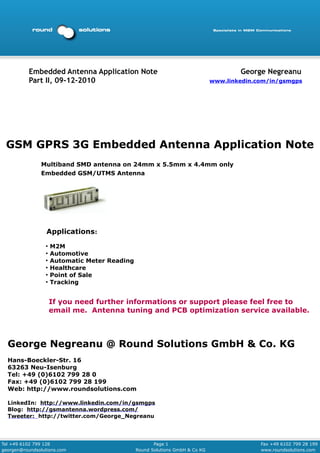
Multiband SMD antenna on 24mm x 5.5mm x 4.4mm only
Embedded GSM/UTMS Antenna
Applications:
●
M2M
●
Automotive
●
Automatic Meter Reading
●
Healthcare
●
Point of Sale
●
Tracking
If you need further informations or support please feel free to
email me. Antenna tuning and PCB optimization service available.
George Negreanu @ Round Solutions GmbH & Co. KG
Hans-Boeckler-Str. 16
63263 Neu-Isenburg
Tel: +49 (0)6102 799 28 0
Fax: +49 (0)6102 799 28 199
Web: http://www.roundsolutions.com
LinkedIn: http://www.linkedin.com/in/gsmgps
Blog: http://gsmantenna.wordpress.com/
Tweeter: http://twitter.com/George_Negreanu
Tel +49 6102 799 128 Page 1 Fax +49 6102 799 28 199
georgen@roundsolutions.com Round Solutions GmbH & Co KG www.roundsolutions.com
2. Embedded Antenna Application Note George Negreanu
Part II, 09-12-2010 www.linkedin.com/in/gsmgps
Table of Contents
1 Introduction 3
2 Mechanical Specification 4
3 Electrical Specification 4
4 Measurement 5
4.1 Electrical Characteristics 5
5 Radiation Characteristics 6
6 Gain Pattern Measurement Data 7
7 Soldering Recommendations 9
7.1 Land Pattern 9
7.2 Placing of antenna 9
8 Soldering Profile 11
9 Packing 11
10 Development Process Proposal 12
Tel +49 6102 799 128 Page 2 Fax +49 6102 799 28 199
georgen@roundsolutions.com Round Solutions GmbH & Co KG www.roundsolutions.com
3. Embedded Antenna Application Note George Negreanu
Part II, 09-12-2010 www.linkedin.com/in/gsmgps
1 Introduction
Multiband SMD antenna on 24 mm x 5.5 mm x 4.4 mm only
Application Note based on antenna ANT-GXE474 GSM GPRS and 3G
The ANT-GXE474 multiband cellular antenna builds on the success of
several SMD tri-band antennas, by extending functionality to cover all
worldwide cellular bands between 800 MHz and 2200 MHz – GSM, CDMA,
DCS, PCS, WCDMA, UMTS, HSPA, GPRS and EDGE.
This IFA antenna is particularly suited for mounting on the edge of a PCB.
It measures 24 mm x 5.5 mm x 4.4 mm and is delivered on tape and reel
for efficient and accurate assembly.
The ANT-GXE474 is also available as mirrored design (ANT-GXE474M) if
the standard design will not fulfil layout/alignment requirements.
If tuning is required it can be tuned for the device environment with no
need for new tooling. The antenna is robust enough to meet all
temperature and mechanical specifications required for automotive
environments.
Typical applications include automotive, remote monitoring, M2M,
telematics, telemedicine, AVL, utility metering, mobile devices, point-of-
sale, navigation, location based services and communication products.
Tel +49 6102 799 128 Page 3 Fax +49 6102 799 28 199
georgen@roundsolutions.com Round Solutions GmbH & Co KG www.roundsolutions.com
4. Embedded Antenna Application Note George Negreanu
Part II, 09-12-2010 www.linkedin.com/in/gsmgps
2 Mechanical specification
Electrode Silver
Dimensions in mm (L x W x H) 24.0 x 5.5 x 4.4
Operating Temperature -35 ~ +85
Unit: mm Tolerance 0.15 mm
3 Electrical Specifications
Item GSM850/900 GSM 1800 GSM 1900 UMTS 2100
Frequency
824 ~ 960 1710 ~ 1850 1850 ~ 1990 1920 ~ 2170
[MHz]
VSWR 3.0 : 1 max. 3.0 : 1 max. 3.0 : 1 max. 3.0 : 1 max.
Peak Gain 1.5 dBi 3.5 dBi 3.5 dBi 3.5 dBi
Min Eff [%] 45% 79% 87% 90%
Polarization Linear
Radiation
Omni-directional
Pattern
Nominal
50 Ohm
Impedance
Ground
106 mm x 45 mm
plane size
Matching
Tuning by changed ground plane / matching circuit as option
tuning
These values are measured on the matched reference test board.
Tel +49 6102 799 128 Page 4 Fax +49 6102 799 28 199
georgen@roundsolutions.com Round Solutions GmbH & Co KG www.roundsolutions.com
5. Embedded Antenna Application Note George Negreanu
Part II, 09-12-2010 www.linkedin.com/in/gsmgps
4 Measurement
Set for measurement with test board version
Board size: 114x45mm
Antenna Radiation the coordinate
system
[X axis: the axis of rotation]
4.1 Electrical Characteristic
Antenna matching on the reference test board
S11(VSWR) Quad Band (GSM850, DCS, PCS, UMTS)
Tel +49 6102 799 128 Page 5 Fax +49 6102 799 28 199
georgen@roundsolutions.com Round Solutions GmbH & Co KG www.roundsolutions.com
6. Embedded Antenna Application Note George Negreanu
Part II, 09-12-2010 www.linkedin.com/in/gsmgps
5 Radiation Characteristics
Measurement setup, 6 m x 3 m x 3 m Anechoic Chamber, Matching on the
standard test board (114 mm x 45 mm) ,Temperature 25 ºC / Humidity 50~55%
Tel +49 6102 799 128 Page 6 Fax +49 6102 799 28 199
georgen@roundsolutions.com Round Solutions GmbH & Co KG www.roundsolutions.com
7. Embedded Antenna Application Note George Negreanu
Part II, 09-12-2010 www.linkedin.com/in/gsmgps
6 Gain pattern measurement data
Tel +49 6102 799 128 Page 7 Fax +49 6102 799 28 199
georgen@roundsolutions.com Round Solutions GmbH & Co KG www.roundsolutions.com
8. Embedded Antenna Application Note George Negreanu
Part II, 09-12-2010 www.linkedin.com/in/gsmgps
Tel +49 6102 799 128 Page 8 Fax +49 6102 799 28 199
georgen@roundsolutions.com Round Solutions GmbH & Co KG www.roundsolutions.com
9. Embedded Antenna Application Note George Negreanu
Part II, 09-12-2010 www.linkedin.com/in/gsmgps
7 Soldering recommendations
7.1 Soldering Land Pattern
A 25
B 5.5
C 2.3
D 20.4
E 1.8
F 1.9
7.2 Placing of antenna
Thickness impedance(ohm)
(mm) Area1 Area2
0.8 66.89 44.56
1.0 65.01 50.01
1.6 61.42 60.49
Dimensions of PCB tracks are calculated on
PCB with FR4 1mm. If you use other thickness
of FR4 then the impedance of the PCB tracks
will be changed and mismatched.
The drawing above shows a 4 component
matching ciruit. For optimal performance a
5-components matching circuit is
recommended:
Tel +49 6102 799 128 Page 9 Fax +49 6102 799 28 199
georgen@roundsolutions.com Round Solutions GmbH & Co KG www.roundsolutions.com
10. Embedded Antenna Application Note George Negreanu
Part II, 09-12-2010 www.linkedin.com/in/gsmgps
C1:
C2:
C3: 3.6 pF (GJM Murata) 402
L1: N/A
L2: 0.5 pF (GJM Murata) 402
3.9 nH (WE-MK Würth) 402
1.8 pF (Tayo) 402 (towards C1)
Remarks: nH (WE-MK Würth)402 (toward C2)
2.7
• C1=3.6 pF (Murata GJM) interferes with the critical frequency 960
MHz. With smaller values the frequency can be shifted to higher
frequency
• L2 consists of 2 components (1.8 pF & 2.7nHthe upper band be
C3=0.5 pF (Murata GJM) optimises the middle of which should
placed as close as possible)
• (GSM1800, 1900, UMTS). The value can be between 0 und 1 pF
size of components (402) in mass production. It has to be the same
• Take care that you use same manufacturer, same value and same
than with your tested and measured prototype PCBs
• Take care that your prototypes and your mass production PCB
material is 100% the same
• The quality of matching circuit components influences the
performance of the matching circuit. We strongly recommend using
0402 type of SMD components.
3.6 pF (GJM Murata) 402
0.5 pF (GJM Murata) 402
3.9 nH (WE-MK Würth) 402
1.8 pF (Tayo) 402
2.7 nH (WE-MK Würth)402
Tel +49 6102 799 128 Page 10 Fax +49 6102 799 28 199
georgen@roundsolutions.com Round Solutions GmbH & Co KG www.roundsolutions.com
11. Embedded Antenna Application Note George Negreanu
Part II, 09-12-2010 www.linkedin.com/in/gsmgps
8 Soldering profile
This product is designed for reflow
soldering only. Do not use flow
(wave) soldering.
Use non-activated flux
(Cl content 0.2% max.)
Follow the recommended
soldering conditions to avoid
damage.
Reflow-cycle is max. 3 times.
9 Packing
Tape Dimension (unit: mm)
Surface resistance
1) Carrier tape : Max 10 11Ω
2) Cover tape : Max 10 11Ω
3) Reel : Max 10 11Ω
Tel +49 6102 799 128 Page 11 Fax +49 6102 799 28 199
georgen@roundsolutions.com Round Solutions GmbH & Co KG www.roundsolutions.com
12. Embedded Antenna Application Note George Negreanu
Part II, 09-12-2010 www.linkedin.com/in/gsmgps
Description of Reel
Material: Plastic reel, GPPS (General Purpose Poly Styrene) resin
10 Development process proposal
Design review of PCB layout and PCB tracks by Round Solutions
(PDF file with pictures of PCB layers, size of PCB (ground plane) and
pictures of product or graphics of the product
Sample PCB made by customer with same value of components
(C1, C2, L1, L2)
Prototype PCB with same value of components in final plastic
enclosure
Optimisation of PCB tracks and matching circuit by customer,
consulting partner of customer or Round Solutions
Production of a small lot of products and tests
Mass production
Tel +49 6102 799 128 Page 12 Fax +49 6102 799 28 199
georgen@roundsolutions.com Round Solutions GmbH & Co KG www.roundsolutions.com