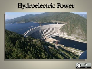
Hydro-Electric Power
•Als PPTX, PDF herunterladen•
45 gefällt mir•11,308 views

Hydroelectric power plants harness the kinetic energy of flowing water to generate electrical power. There are several types of hydroelectric power plants classified by their hydraulic characteristics and operating head. Run-of-river plants utilize minimum river flows without storage, while storage plants feature upstream reservoirs. Pumped storage plants pump water back uphill during off-peak hours. Tidal plants use the difference between high and low tides. Classification by head includes low-head (<15m), medium-head (15-60m), and high-head (>60m) schemes. The major components of a typical hydroelectric scheme are the intake, penstocks, turbines, generators, and powerhouse. Impulse turbines like Pelton wheels and reaction turbines

Empfohlen
Weitere ähnliche Inhalte
Was ist angesagt?
Was ist angesagt? (20)
Ähnlich wie Hydro-Electric Power
Ähnlich wie Hydro-Electric Power (20)
Mehr von GAURAV. H .TANDON
Mehr von GAURAV. H .TANDON (20)
Kürzlich hochgeladen
Kürzlich hochgeladen (20)
Hydro-Electric Power
- 2. Syllabus Hydroelectric Power Low, Medium and High head plants, Powerhouse components, Hydel schemes.
- 4. Hydro Electric Power • Hydropower or water power is power derived from the energy of falling water, which may be harnessed for useful purposes. Since ancient times, hydropower has been used for irrigation and the operation of various mechanical devices, such as watermills, sawmills, textile mills, dock cranes, and domestic lifts.
- 6. Hydro Electric Power • When a coil is rotated in a magnetic field, electricity is generated, thus in order to produce electrical energy, it is necessary that we should produce mechanical energy, which can be used to rotate the coil. The mechanical energy is produced by running a turbine by energy of fuels or flowing water. Thus when the energy of flowing water is used to run the turbine, then the electricity generated is called Hydroelectric power. This scheme is known as hydel scheme and the power station is known as hydel power station or hydroelectric power station.
- 8. Hydro Electric Power • In a Hydro power scheme a certain quality of water at a certain potential head, is essentially made to flow through the turbines. The head causing flow, runs the turbine blades, and thus producing electricity from the generator coupled to the turbine.
- 9. Classification of Hydel Plants • Classification of Hydro plants based on Hydraulic Characteristics. • On the basis of this characteristics, the hydro plants may be divided into the following types. • Run-off river plants • Storage plants • Pumped storage plants • Tidal plants
- 10. Run-off River Plants • Runoff river plants are those which utilizes the minimum flow in a river having no appreciable pondage on its upstream side. A weir or a barrage is some times constructed across a river simply to raise and maintain the water level at a pre- determined level within narrow limits of fluctuations, either solely for the power plants or for some other purpose where the power plant may be incidental. Such a scheme is essentially a low head scheme and may be suitable only on a perennial river having sufficient dry whether flow.
- 12. Storage Plants • A storage plant is essentially having an upstream storage reservoir of sufficient size, so as to permit sufficient carry-over storage from the monsoon season to the dry summer season, and thus to develop a firm flow substantially more than the minimum natural flow. In this scheme, a dam is constructed across the river, and the power house may be located at the foot of the dam.
- 13. Storage Plants
- 14. Pumped Storage Plants • A pumped storage plant generates power during peak hours, but during the off-peak hours, water is pumped back from the tail water pool to the head water pool for future use. The pumps are run by some secondary power from some other plants in the system. The plants is thus primarily meant for assisting an existing thermal plant or some hydel plant.
- 16. Tidal Plants • Tidal plants for generation of hydro electric power are the recent and modern advancements and essentially works on the principle that there is a rise in a sea water during high tide period and a fall during the low tide period. The water rises and falls during the day. The advantage of this rise and fall is taken in a tidal plant. In other words the difference between high and low tide level is utilized to generate power.
- 17. Tidal Plants • This is accomplished by constructing a basin separated from the ocean by a partition wall and installing turbines in openings through this wall. Water passes from the ocean to the basin drainage high tides, and thus running the turbines and generating electric power. During low tide, the water from the basin run back to the ocean which can again be utilized to generate electric power for either direction. Such a plants are useful where the tidal range is high.
- 18. Tidal Plants
- 19. Classification of Hydro power plant based on Operating Head of turbine • On the basis of operating head the plants may be divided into the following types: • (i) Low head Scheme ( Head < 15 m) • (ii) Medium Head Scheme ( Head varies between 15 to 60 m) • (iii) High head scheme (Head > 60 m)
- 20. Classification of Hydro power plant based on Operating Head of turbine • Low Head Scheme • A low head scheme is one which uses water head of less than 15 m or so. A runoff river plant is essentially a low head scheme. In this Scheme, a weir or a barrage is constructed to raise the water level , and the power house is constructed either in continuation with the barrage or at some distance downstream of the barrage, where water is taken to the power house through an intake canal.
- 21. Low Head Scheme
- 22. Low Head Scheme
- 23. Classification of Hydro power plant based on Operating Head of turbine • Medium Head Scheme • A medium head scheme is one which uses water head varying between 15 to 60 m or so. This scheme is thus essentially a dam reservoir scheme, although the dam height is mediocre. This scheme is having features somewhere between low head scheme and high head scheme.
- 25. Classification of Hydro power plant based on Operating Head of turbine • High Head Scheme • A high Head Scheme is the one which uses water head of more than 60 m or so. A dam of sufficient height is therefore, required to be constructed, so as to store water on the upstream side and to utilize this water throughout the year. High head schemes upto 1800 m have been developed. The common e.g. of such dams are bhakra dam in Punjab and Hoover dam in USA.
- 26. High Head Scheme
- 27. High Head Scheme
- 28. Principle Components of a Hydro- Electric Scheme. • A Hydro electric development scheme ordinarily includes a diversion structure. A conduit to carry water to the turbines, turbines and governing mechanisms, generator, control and switching apparatus, housing for the equipment, transformers and transmission lines to the distribution centres and a penstock gate, a forway, a surge tank, and other appurtenances may be required. A tail race channel from the power house back to the river must be provided, if the power house is situated at such a place that the draft tubes cannot discharge water directly into the river.
- 29. Principle Components of a Hydro- Electric Scheme. • No two power development schemes are exactly alike and each will have its unique problem of design and construction. The choice of a particular type of plant at a given site depends upon various factors, such as: • General available topography of the area • Available head • Available flow • Availability of other type of power station in the vicinity. • Requirement of power for industry, etc • Political influence of the area, etc.
- 30. Principle Components of a Hydro- Electric Scheme.
- 31. Principle Components of a Hydro- Electric Scheme. • The major components of a hydroelectric scheme are described below: • The Forway • A foreway is a storage basin or any other large body of water situated infront of intake. Its main function is to temporarily store the water which is rejected by the plant due to reduced load during off-peak hours, and also to meet the instantaneous increased demand when the load is suddenly increased. The foreway, therefore, absorbs the short interval variations in water demand and corresponding fluctuations in power load.
- 32. The Foreway • In many cases canal leads the water to the turbines, the canal itself may be large enough to absorb these flow variations. When the canal is long its section is sometimes enlarged at the ends, so as to provide necessary temporary storage. In many cases , when a reservoir is constructed by building dam, and the water is taken to the power house directly from the reservoir through penstocks, the reservoir itself acts as a foreway
- 33. The Forway
- 34. Principle Components of a Hydro- Electric Scheme • Intake Structures • The foreway is provided with some type of intake structure. To direct water into the penstocks. Various types of intakes are used depending upon the local conditions. • Intakes should be provided with trash racks so as to prevent the entry of debris. Into the penstocks, and thus to avoid the possible damage to the gates.
- 35. Intake Structures • A floating broom is often placed in the storage reservoir so as to trap as mush ice and floating debris as possible, and thus to avoid their entry into the canal. At places, where severe winters do occur, provisions is made so as to minimize the ice trouble in the foreway. The trash rack must be electrically heated, so as to prevent clinging of ice with them. Sometimes, an air-bubbler system which agitates the water in the vicinity of the trash rack and brings warmer water to the surface, is also used
- 36. Intake Structures • Besides Trash racks, other accessories of an intake structure are: • Rakes and trolley arrangements • Ice removal equipments such as a floating boom, electrical heating device for trash racks, etc. • Penstock closing gates with their hoisting mechanisms.
- 39. Principle Components of a Hydro- Electric Scheme • Penstock • Penstocks are the huge diameter pipes which carry water under pressure from the reservoir to the turbine. The structural design of a penstock is essentially similar to that of any other pipe, but because of the possibility of sudden load changes, design against water hammer is essential. Short length penstocks are generally designed to take extra pressure by providing heavier pipe wall. Slow-closing valve are then provided, so as to reduce these extra pressures. However in long penstock a surge tank is provided so as to absorb water high pressures and to provide water to meet sudden load increases.
- 40. Penstock • Penstock closing gates are usually provided at the entrance in the foreway. The gate can be closed to permit repair of penstock. An air vent and vent pipe connecting the top of penstock with open air, is provided downstream from the gates. Such a vent permits the entry of air into the penstock, as soon as the gates are closed and water is drawn off through the turbine wheels
- 41. Penstock
- 42. Penstock
- 43. Principle Components of a Hydro- Electric Scheme • The penstock should be located at such a level that sufficient water depth is provided above the penstock entrance in the foreway. If this is not so, and too little water depth is available, vortices and whirlpools will tend to form, which may carry air in the penstock and turbine wheels, and thus lowering efficiency of the turbine. • Sharp bends must be avoided in the penstocks, because they cause loss of head and require special anchorages.
- 44. Principle Components of a Hydro- Electric Scheme • Surge Tank or Surge Chamber • The simplest type of a surge chamber consists of a cylindrical chamber open to atmosphere and connected to the penstock as close to the power house as possible. • When the load is rejected by the power house turbines. When the load is rejected by the power house turbine, the water level in the surge chamber rises, and decelerates the flow upstream of it. But when additional load comes, the immediate demand is met by drawing water from the surge chamber, which accelerates the flow gradient and thus accelerates the flow in the reservoir. A surge tank therefore reduce the pressure fluctuations in the conduit pipe considerably, and thus prevents additional water hammer pressure from being exerted upon the wall of the conduit.
- 45. Principle Components of a Hydro- Electric Scheme • Various types of surge tanks such as (i) simple surge tank (ii) Throttled surge chamber (iii) Differential surge chamber (iv) Multiple surge chamber. • The main advantage of differential type of surge tank over simple tank lies in the fact that the retarding & accelerating heads are developed more quickly in differential types
- 46. Surge Tank or Surge Chamber
- 47. Surge Tank or Surge Chamber
- 48. Surge Tank or Surge Chamber
- 49. Principle Components of a Hydro- Electric Scheme • Hydraulic Turbines • Turbines are machines which convert hydraulic energy into mechanical energy. The mechanical energy so developed by the turbine is then used to generate electric energy by direct coupling of the shaft of the turbine with generator. • In general, a turbine consists of wheel which is provided with special designed blades or buckets. The water having large hydraulic energy is made to strike the runner, and thus cause it to rotate. This rotation of the turbine runner is passed on to the generator by coupling the generator and turbine together through the turbine shaft. This results in rotating the generator armature, and thus producing electrical power, called hydroelectric power.
- 51. Principle Components of a Hydro- Electric Scheme • Hydraulic Turbines may be of two classes: • (i) Impulse Turbines or Velocity Turbines and • (ii) Reaction turbines or Pressure turbines • These are discussed below: (i) Impulse Turbine. • The important example of an impulse type of turbine is Pelton’s wheel In such a turbine, all the available potential energy of water is converted into kinetic energy by passing the penstock water through a single nozzle. The water coming out of the nozzle in the form of free jet is made to strike a series of buckets mounted on the periphery of a wheel. This causes the wheel to revolve in open air, and water is in contact with only a part of the wheel at a time. • An impulse turbine is essentially a low speed turbine and is used for high heads of the order of 150 to 1000m. Since it works under high heads. Comparatively less quality of water. Since it works under high heads, comparatively less quantity of water is required. It is therefore used for high heads and low discharges.
- 52. Impulse Turbine.
- 54. Principle Components of a Hydro- Electric Scheme (ii) Reaction Turbine • The important example of reaction turbine are (i) Fancis turbine; and Kaplan turbine. A reaction turbine is one in which only a part of potential energy of water is converted into velocity head and the balance remains as pressure head. Thus the water entering the turbine possesses pressure as well as kinetic energy. The wheel is rotated under the action of both these forces. The water leaving the turbine also contains some pressure as well as velocity head. The pressure at the inlet is much higher than the pressure at the outlet. Since the entire flow takes place under pressure, a closing case is absolutely necessary, so as to prevent access of atmosphere air into the turbine. Since the water flows under pressure through such a turbine, the wheel of this turbine are submerged, and water enters all around the periphery of the wheel.
- 55. Kaplan Turbine
- 56. Kaplan Turbine
- 57. Francis Turbine
- 58. Francis Turbine
- 59. Difference Between Pelton’s and Francis Turbine • In a Pelton’s wheel, the total potential head is changed into kinetic head for affecting the motion of the runner; while in a francis wheel, only a part of it is converted. • Water strikes only a few buckets at a time in Pelton’s wheel while in francis turbine wheel the water flows like that in a closed conduit. The runner is always full of water, and thus all the blades are simultaneously stricken by water. • In Pelton’s wheel, the water falls freely to the atmosphere; while in Francis wheel, the water is taken upto the tailrace by means of a closed draft tube, and thus, the whole passage of water is totally enclosed.
- 60. Principle Components of a Hydro- Electric Scheme Power House • A power house is a building consisting of a substructure to support the hydraulic and electric equipment and a super structure to house and protect this equipment. For most of the plants which are equipped with reaction turbines, the substructure usually consists of a concrete block extending from the foundation to the generator floor with waterways formed within it. They are cast integrally while pouring concrete. • The super structure is a building which generally accommodates the generator and excitors on the ground floor, and the switch board and control room on the mezzanine floor. Vertical turbines are placed on the ground floor along side the generators. A travelling crane spanning the width of the power house, is generally provided in every power hose, so as to facilitate the lifting of heavy machines.
- 61. Power House
- 62. Power House
- 63. Merits & Demerits of Hydro Electric Power Merits • Once a dam is constructed, electricity can be produced at a constant rate. • If electricity is not needed, the sluice gates can be shut, stopping electricity generation. The water can be saved for use another time when electricity demand is high. • Dams are designed to last many decades and so can contribute to the generation of electricity for many years / decades.
- 64. Merits & Demerits of Hydro Electric Power • The Reservoir that forms behind the dam can be used for water sports and leisure / pleasure activities. Often large dams become tourist attractions in their own right. • The Reservoir water can be used for other purposes such as irrigation. • Minimum operating staff is required for the operation of hydro power plant. • Non Polluting and hence environmental friendly energy is produced. • Low cost of energy generation & maintenance.
- 65. Merits & Demerits of Hydro Electric Power Demerits • Land acquisition is the major problem as construction of dam causes large submergence of land. Many political, regional, and social hurdles comes in the process of land acquisition • Hydro- Power project takes long time for clearance. • Rehabilitation and resettlement of displaced people is a major problem associated to any hydropower project. • Large scale initial investment is required.
- 66. Merits & Demerits of Hydro Electric Power • The high cost of dam construction means that they must operate for many decades to become profitable. • The Submergence of large areas of land means that the natural environment is destroyed. • The building of large dams can cause serious geological damage.
- 67. Merits & Demerits of Hydro Electric Power • Although modern planning and design of dams is good, in the past old dams have been known to be breached this has led to deaths and flooding. • Dams built blocking the progress of a river in one country usually means that the water supply from the same river in the following country is out of their control. This can lead to serious problems between neighboring countries. • Building a large dam alters the natural water table level.
- 68. References • Irrigation Engineering & Hydraulic Structures – Prof. Santosh Kumar Garg – Khanna Publishers • Internet Websites
- 69. THANKS
- 70. “Water links us to our neighbour in a way more profound and complex than any other.” » John Thorson