

Empfohlen
Weitere ähnliche Inhalte
Was ist angesagt?
Was ist angesagt? (20)
Ähnlich wie Cofferdams
Ähnlich wie Cofferdams (20)
Mehr von GAURAV. H .TANDON
Mehr von GAURAV. H .TANDON (20)
Kürzlich hochgeladen
Kürzlich hochgeladen (20)
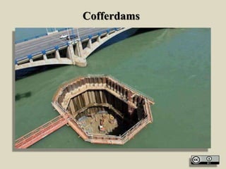
Cofferdams
- 1. Cofferdams
- 2. Topics • Coffer Dams: Definition, uses, selection of coffer dams, types of coffer dams, design features of coffer dams; leakage prevention, economic height.
- 3. Cofferdams
- 4. Cofferdams • “A cofferdam is a temporary structure designed to keep water and/or soil out of the excavation in which a bridge pier or other structure is built.” - Standard Handbook of Heavy Construction
- 5. Cofferdams • Cofferdams are temporary enclosures to keep out water and soil so as to permit dewatering and construction of the permanent facility (structure) in the dry.
- 6. Cofferdams
- 7. Cofferdams • Because cofferdams are typically constructed under adverse conditions in a marine environment, and because significant deformations of elements may occur at various stages of construction, it is difficult to maintain close tolerances. • Ample provisions must be made for deviations in dimensions so that the finished structure may be constructed according to plan.
- 8. Cofferdams
- 9. Cofferdams • The loads imposed on the cofferdam structure by construction equipment and operations must be considered, both during installation of the cofferdam and during construction of the structure itself. • Removal of the cofferdam must be planned and executed with the same degree of care as its installation, on a stage-by-stage basis.
- 10. Cofferdams
- 11. Cofferdams • In cofferdam construction, safety is a paramount concern, since workers will be exposed to the hazard of flooding and collapse.
- 12. Safety Requires • good design • proper construction • verification that the structure is being constructed as planned • monitoring the behaviour of the cofferdam and surrounding area • provision of adequate access • light and ventilation, and • attention to safe practices on the part of all workers and supervisors.
- 13. Cofferdams
- 14. Cofferdams • Types of Cofferdam • Braced • Earth-Type • Timber Crib • Double-Walled Sheet Pile • Cellular
- 16. Timber Crib
- 18. Braced Cofferdam
- 19. Cofferdams • Advantages of Cofferdam • Allow excavation and construction of structures in otherwise poor environment • Provides safe environment to work • Contractors typically have design responsibility • Steel sheet piles are easily installed and removed • Materials can typically be reused on other projects
- 20. Cofferdams
- 21. Cofferdams Items needed for Installation • Pile driving hammer • Vibratory or Impact • Crane of sufficient size • Steel sheet piles are typically used • H-piles and/or wide-flange beams for Wales and stringers • Barges may be required
- 22. Cofferdams Barges Wales, Struts, Pile Arrangements
- 23. Cofferdams Types Of Imposed Loads • Hydrostatic Pressure • The maximum probable height outside the cofferdam during construction and the water height inside the cofferdam during various stages of construction need to be considered.
- 24. These result in the net design pressure shown below
- 25. Cofferdams Types Of Imposed Loads • Forces due to Soil Loads • The soils impose forces, both locally on the wall of the cofferdam and globally upon the structure as a whole. These forces are additive to the hydrostatic forces. • Lateral force on sheet-pile walls, causes bending in the sheets
- 26. Cofferdams Types Of Imposed Loads
- 27. Current Forces on Structure • Current Forces on Structure • With a typical cofferdam, the current force consists not only the force acting on the normal projection of the cofferdam but also on the drag force acting along the sides.
- 28. Wave Forces • Wave Forces • Waves acting on a cofferdam are usually the result of local winds acting over a restricted fetch and hence are of short wavelength and limited to height. • Waves can also be produced by passing boats and ships, especially in a restricted waterway
- 29. Wave Forces
- 30. Ice forces • Ice forces • These are of two types: • The force exerted by the expansion of a closed-in solidly frozen-over area of water surface (static ice force) and the forces exerted by the moving ice on breakup (dynamic ice force).
- 31. Ice forces
- 32. Cofferdams Types Of Imposed Loads • Seismic Loads • These have not been normally considered in design of temporary structures in the past. For very large, important, and deep cofferdams in highly seismically active areas, seismic evaluation should be performed. • Accidental loads • These are the loads usually caused by construction equipment working alongside the cofferdam and impacting on it under the action of waves
- 33. Cofferdams Types Of Imposed Loads • Scour • Scour of the river bottom or seafloor along the cofferdam may take place owing to river currents, tidal currents, or wave-induced currents. Some of the most serious and disastrous cases have occurred when these currents have acted concurrently. • A very practical method of preventing scour is to deposit a blanket of crushed rock or heavy gravel around the cofferdam, either before or immediately after the cofferdam sheet piles are set. A more sophisticated method is to lay a mattress of filter fabric, covering it with rock to hold it in place.
- 34. Cofferdam Components Cofferdam Components • Sheet piling • Bracing frame • Concrete seal • Bearing piles
- 35. Sheet Piling
- 36. Bracing frame
- 38. Cofferdams • The typical cofferdam, such as a bridge pier, consists of sheet piles set around a bracing frame and driven into the soil sufficiently far to develop vertical and lateral support and to cut off the flow of soil and, in some cases the flow of water.
- 39. Cofferdams
- 40. Cofferdams • The structure inside may be founded directly on rock or firm soil or may require pile foundations. In the latter case, these generally extend well below the cofferdam. • In order to dewater the cofferdam, the bottom must be stable and able to resist hydrostatic uplift. Placement of an underwater concrete seal course is the fastest and most common method.
- 41. Cofferdams
- 42. Cofferdams • An underwater concrete seal course may then be placed prior to dewatering in order to seal off the water, resist its pressure, and also to act as a slab to brace against the inward movement of the sheet piles in order to mobilize their resistance to uplift under the hydrostatic pressure.
- 43. Cofferdams
- 44. Cofferdams Construction Sequence • For a typical cofferdam, such as for a bridge pier, the construction procedure follow the listed pattern. • Pre-dredge to remove soil or soft sediments
- 45. Cofferdams Construction Sequence • Drive temporary support piles • Temporarily erect bracing frame on the support piles.
- 46. Cofferdams Construction Sequence • Set steel sheet piles, starting at all four corners and meeting at the center of each side. • Drive sheet piles to grade. • Block between bracing frame and sheets, and provide ties for sheet piles at the top as necessary.
- 47. Cofferdams Construction Sequence • Excavate inside the grade or slightly below grade, while leaving the cofferdam full of water.
- 48. Cofferdams Construction Sequence • Drive bearing piles. • Place rock fill as a levelling and support
- 49. Cofferdams Construction Sequence • Place Tremie Concrete Seal.
- 50. Cofferdams Construction Sequence • Tremie concrete seal.
- 51. Cofferdams Construction Sequence • Tremie concrete seal.
- 52. Cofferdams Construction Sequence Check blocking between bracing and sheets. • De-watering. • Construct new structure
- 53. Cofferdams
- 54. Cofferdams Construction Sequence • Construct new structure. • Flood cofferdam.
- 55. Cofferdams Construction Sequence • Remove sheet piles. • Remove bracing. • Backfill
- 56. Cofferdams • Cofferdams • Braced Cofferdam Construction • Install Wale and Strut System for Framework /Template
- 57. Cofferdams
- 58. Cofferdams • Braced Cofferdam Construction • Install Wale and Strut System for Framework /Template
- 59. Cofferdams
- 60. Cofferdams
- 61. Design Features of Cofferdams • The design of a cofferdam depends on various factors such as • Hydrostatic head of water • Dimensions of the area to be covered by the cofferdam • Subsoil Conditions • Fluctuations of outside water level • Possibility of erosion • Floating logs, etc.
- 62. Design Features of Cofferdams • As it is, sometimes not possible to determine accurately the forces due to these factors, the worst condition should be assumed in the design of the cofferdam to prevent its failure. • It is thus, clear that a purely theoretically designed cofferdam may fail for factors unaccounted in its design. • It has, therefore, become necessary to combine practical knowledge or experience with the theoretical aspect in the design of a cofferdam.
- 63. Design Features of Cofferdams • The various thumb-rules for width and depth of cofferdam are as follows: • For H < 3 m, W = W • H > 3, W= 3 + ½ (H-3) • Where, • W= Width of cofferdam in metres • H= Height of water above river bed in metre.
- 64. Prevention of Leakage in Cofferdams • The water enters the cofferdam in the two ways, namely, by leakage through the sheet piling and by under flow. • The measures employed to prevent the leakage in a cofferdam are as follows: • If the entry of water is through the fissures or cracks of the rock, it can be stopped by pumping cement grout through pipes of about 10 cm in diameter. • The material such as clay, sand, ashes, etc. may be damped all round the cofferdam to reduce the quantity of entering water.
- 65. Prevention of Leakage in Cofferdams
- 66. Prevention of Leakage in Cofferdams • Leakage in case of a single wall cofferdam may be prevented by placing a V-shaped wooden trough outside each joint and filling it with puddle. • The interlocks of steel sheet piles may be provided with sufficient quantity of grease before driving. Fine materials carried by water will stick and it will make the joints effective in preventing leakage of water. • If the leakage is of serious nature, it is reduced by providing tarpaulin which is canvas coated tar. The canvas is placed over the area of leakage and it should be seen that it is not disturbed from its position by the force.
- 67. Prevention of Leakage in Cofferdams
- 68. References • Cofferdam • https://en.wikipedia.org/wiki/Cofferdam • Cofferdam • http://www.cv.titech.ac.jp/~courses/atce2/Lesson4.pdf • Cofferdams • http://courses.washington.edu/cm510/cofferdams.pdf • How The Cofferdam Process Works • https://www.damitdams.com/how-a-cofferdam-works/ • Types Of Cofferdams • https://theconstructor.org/water-resources/types-of- cofferdams-construction-details/13807/
- 69. Thanks…