
Empfohlen
Empfohlen
Weitere ähnliche Inhalte
Andere mochten auch
Ähnlich wie VEM CASE STUDIES - PREMIX SYSTEM Optimization
Ähnlich wie VEM CASE STUDIES - PREMIX SYSTEM Optimization (20)
Kürzlich hochgeladen
Kürzlich hochgeladen (20)
VEM CASE STUDIES - PREMIX SYSTEM Optimization
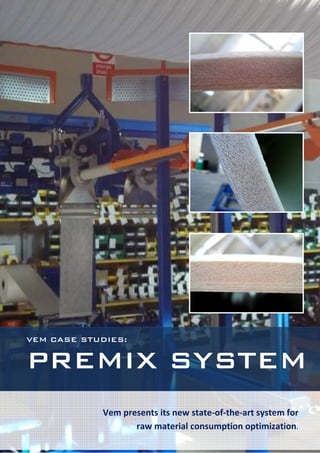
- 1. VEM CASE STUDIES: PREMIX SYSTEM Vem presents its new state-of-the-art system for 1 VEM CASE STUDIES – raw material consumption optimization. PREMIX SYSTEM
- 2. FOREWORD This technology was developed to reduce resin consumption in the core, as well as improving the mixing of resin and sand, especially when the sand granulometry is not exactly to VEM’s specifications. The premix system is convenient for the production of pipe with a minimum wall thickness of 10mm. The premix pipe does not Photo 1: China premix in production, first release. have the same design as that of a standard pipe: there is no chop in the core and there OUR TESTS st are three different resin dosing systems: 1 The first test was performed in a plant in China skin, premix mortar core and finally the 2nd in 2009 with the first version of premix skin. machine, visible in photo no. 1 above. The mortar core is made of a polypropylene The pipe produced was ND800 NP6 ST10000 veil that contains the resin mixed with the and the laboratory test results were aligned to sand; afterwards the premix “sausage” is the pipe design program. The composition was wound onto the mandrel. in accordance with the pipe design expected The premixing machine has two different data, as indicated in the following table: extruders, depending on the wall thickness. The second one is useful when the core thickness is > 25 mm, for example: STANDARD SAND PREMIX RAW MATERIALS SYSTEM(%) SYSTEM(%) - ND 2000 NP 10 SN 10.000 (25,87mm) - ND 2300 NP 10 SN 7.500 (25,46mm) Sand 54 66 - ND 3000 NP 10 SN 5.000 (26,50mm) Hoop 7.9 7.4 The old release had the static mixer fixed on Chop 6.8 2.9 the premix structure. As you can see from the Resin 30.4 23.6 picture, the device was designed to guarantee Total resin 27.13 22.14 the minimum gap from extruder output and Kg/m the pipe on production. 2 VEM CASE STUDIES – PREMIX SYSTEM
- 3. The variation from design was: L.O.I DEV (%) Resin 1.1 Sand 0.5 Chop -0.8 Hoop -2,85 Photo 2: Turkey release premix The second test was performed in Turkey L.O.I. DEV (%) where a ND1300 NP6 SN2500 was produced. Resin 0,43 The system was stable enough to produce a Sand 1,96 very well compacted pipe core, thanks to a Chop 0,02 second compaction roller together with Hoop -2,85 controlled vibration. Stiffness respected the design values, namely 3365,58Pa at 5% of deflection. The following tables and pictures explain the above: RAW STANDARD SAND PREMIX SYSTEM(%) SYSTEM(%) MATERIALS Sand 40 47 Hoop 20 20.2 Chop 9.3 6.5 Resin 30.3 25.4 Total resin 40 35 Kg/m Photo set 3: see the optimum compaction thanks to the second compaction roller and vibration 3 VEM CASE STUDIES – PREMIX SYSTEM
- 4. A third test was done in Turkey on DN2000 The last test was performed in Syria, where a NP6 SN2500 and the L.O.I. result showed good ND1200 NP6 SN10.000 pipe was made. The values from a composition point of view and production was very smooth and the variation from design: laboratory results showed successful values. L.O.I. DEV (%) Resin 1,55 Sand -1,66 Chop -2,22 Hoop 2,23 VEM decided to further develop the Photo 4: Syrian version, premix on trolley and premix guide technology to obtain a more user friendly system: The 2010 release is more user friendly from an 1) Use of a different veil: larger and installation point of view: installation and stronger. removal can be performed in less than 1 hour 2) Use of a forming mouth piece to close thanks to the fast connections and mechanical the sausage and an auto-tensioning facilities. device to make the process stable. 3) Changing of premix position: easier to put it into operation. From a production point of view, the ND1200 4) Chopper plate conveyors. NP6 SN10.000 pipe was designed as shown 5) Use of a larger core area and a second below, where we have also indicated the compaction roller. expected and actual values: 6) Changing of static mixer position from premix structure to the chopper bridge. 4 VEM CASE STUDIES – PREMIX SYSTEM
- 5. PIPE DESIGN ACTUAL EXPECTED Resin LOI 23 23,72 (%) Sand (%) 64,7 64,71 Hoop 9,3 9,94 (%) Photo 5: well compacted core Chop (%) 2,9 3,56 Thickness Mm 23,84 23,23 CONCLUSIONS Stiffness 5% Pa 10000 10605 deflection The premixing system allows the production of Axial tensile N/mm 280 354 an extremely competitive pipe thanks to a Hoop tensile N/mm 1448 1669 reduced consumption of resin, approximately between 15 and 20% in the core, depending Circumference mm at elongation on 6,4 2,5 on the pipe recipe, with good mechanical test 1xNP Hydrotest results. mm at 14 5,7 2xNP Since the case studies carried out in Turkey and Syria, VEM continued to develop the premixing system and we are proud to now show you a photo of the latest version: The good compaction of the mortar core is shown in the photo number 5. A combination of pressure compaction roller, gravity roller and vibration in different points contributed to this excellent result. Photo set 6: Premix last release, 2011 version 5 VEM CASE STUDIES – PREMIX SYSTEM