Delhi Call Girls Saket 9711199171 ☎✔👌✔ Whatsapp Hard And Sexy Vip Call
Terex telelift gladiator agrilift 359 telescopic handler service repair manual
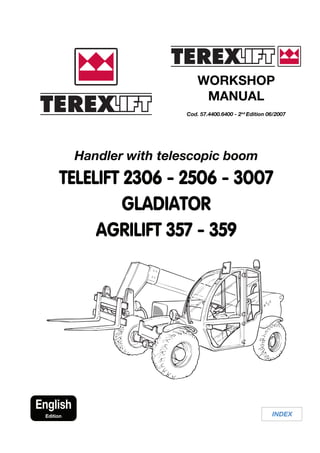
1. WORKSHOP
MANUAL
Cod. 57.4400.6400 - 2nd
Edition 06/2007
INDEX
English
Edition
Handler with telescopic boom
TELELIFT 2306 - 2506 - 3007
GLADIATOR
AGRILIFT 357 - 359
2. Document 57.4400.6400 - 2nd
Edition 06/2007 INDEX
5
TELELIFT Series
CONTENTS
MANUAL CONTENTS
Sect. A GENERAL INFORMATION
Sect. B SAFETY REGULATIONS
Sect. C TECHNICAL OPERATION DATA
Sect. D CHECKS AND ADJUSTMENTS
Sect. E DISMANTLING AND REASSEMBLY
Sect. F TROUBLESHOOTING
Sect. G CARRARO AXLE ASSEMBLY/DISMANTLING (valid for Telelift 2306 - Gladiator)
Sect. G DANA AXLE ASSEMBLY/DISMANTLING (valid for Telelift 2506 - 3007)
Sect. H PERKINS ENGINE MAINTENANCE (valid for Telelift 2306 - Gladiator)
Sect. H DEUTZ ENGINE MAINTENANCE (valid for Telelift 2506 - 3007)
Sect. I REPAIR INSTRUCTIONS - REXROTH PUMP (valid for Telelift 2306 - 2506 - 3007 -
Gladiator)
Sect. L REPAIR INSTRUCTIONS - REXROTH MOTOR (valid for Telelift 2306 - 2506 - 3007
- Gladiator)
Sect. M COMPACT PLUS TRANSMISSION (valid for Agrilift 357 - 359)
3. Document 57.4400.6400 - 2nd
Edition 06/2007 INDEX
6
Date Previous denomination Present denomination Notes
TELELIFT Series
MACHINE CORRESPONDENCE
4. Document 57.4400.6400 - 1st
Edition 05/2004
INDEX
A
1
TELELIFT Series
GENERAL INFORMATION
Section A
GENERAL INFORMATION
SECTION INDEX
A.01 Introduction ......................................................................................... page 2
A.02 Symbols used in the manual ....................................................................... 3
A.03 Abbreviations................................................................................................ 4
A.04 Units of measure .......................................................................................... 5
A.05 Minimum workshop equipment .................................................................. 6
A.06 Special tools and equipment ...................................................................... 7
A.07 Bolt and nut tightening torques .................................................................. 11
A.08 Drill diameters for threads .......................................................................... 13
A.09 Fitting tightening torques ............................................................................ 14
A.10 Threadlockers, thread sealants and gaskets ............................................ 16
A.11 Hoisting instructions.................................................................................... 17
A.12 Weight list of the main parts ....................................................................... 18
A.13 Advice to renew flexible hoses ................................................................... 19
A.14 Repair interventions, welds and weld materials ....................................... 21
A.15 Weld material................................................................................................ 23
A.16 Checks with liquid penetrants .................................................................... 24
A.17 Checks with magnetoscope ....................................................................... 25
A.18 Refilling and product specifications........................................................... 26
A.19 Machine paint coulours ............................................................................... 26
A.20 Lists of recommended spare parts ............................................................ 27
5. Document 57.4400.6400 - 1st
Edition 05/2004
INDEX
A
2
TELELIFT Series
GENERAL INFORMATION
A.01 INTRODUCTION
This manual has been prepared to provide information
about the routine and extraordinary maintenance of the
main units of the machine in a safe and proper way.
STRICTLY COMPLY WITH THE INSTRUCTIONS
GIVEN IN THIS MANUAL!
READ AND UNDERSTAND THIS MANUAL
BEFORE CARRYING OUT ANY INTERVENTION
ON THE MACHINE.
If you are unsure about anything after the reading of
this manual, address to TEREXLIFT Assistance
Service: addresses, phone and fax numbers are
printed in the cover and in the title-page of this
manual.
Keep this manual in the workshop at all times and read
it before carrying out any extraordinary maintenance job.
6. Document 57.4400.6400 - 1st
Edition 05/2004
INDEX
A
3
TELELIFT Series
GENERAL INFORMATION
A.02 SYMBOLS USED IN THE MANUAL
In this manual, any important information starts with a
SPECIAL SYMBOL.
Symbols are also used to direct the reader's attention to
special technical information about the tools to use, the
tightening torques, etc.
There are six safety symbols in this manual, always
combined with keywords that class the situations
according to their degree of dangerousness.
The symbols are always followed by a text explaining the
situation taken into account, the attention to be paid to
such situation, the method and the behaviour to be
adopted.Ifnecessary,itstressesprohibitionsorprovides
instructions to prevent dangers.
Sometimes, it can be followed by illustrations.
The safety symbols are the following:
DANGER
Draws the attention to situations that involve your
own as well as the others’ safety and that can result
in serious or lethal injury.
ELECTRICAL
DANGER
Draws the attention to electrical risks that involve
your own as well as the others’ safety and that can
result in serious injury or lethal injury.
CAUTION
Draws the attention either to situations that involve
your own as well as the others’ safety and that can
result in minor or moderate injury; or to situations
that affect the machine efficiency.
ATTENTION
Draws the attention either to situations that involve
your own as well as the others’ safety and that can
result in minor or moderate injury; or to situations
that affect the machine efficiency.
IMPORTANT
Draws the attention to important technical
information or practical advice that allows for a safer
and more efficient use of the machine.
PROTECT THE
ENVIRONMENT
Drawstheattentiontoimportantenvironment-related
information.
Indicates the number of people needed
for the job
Time expected to do the intervention
(except in case of troubles)
Special tools needed for the job
Weight of the unit to be handled
Tightening torque of bolts and screws
Inspection needed
7. Document 57.4400.6400 - 1st
Edition 05/2004
INDEX
A
4
TELELIFT Series
GENERAL INFORMATION
A.03 ABBREVIATIONS
Abbreviation Definition
Tab. Table
Pag. Page
Sect. Section
Dwg. Drawing
Ref. Reference
CLS Concrete
Mach. Machine
Fig. Figure
Ph. Photo
T.O. Technical Office
T.A.S. Technical Assistance Service
8. Document 57.4400.6400 - 1st
Edition 05/2004
INDEX
A
5
TELELIFT Series
GENERAL INFORMATION
A.04 UNITS OF MEASURE
1 FORCE
The unit of measure of force is the Newton (N)
For the conversion:
1 N = 0.1019 kg
1 kg = 9.81 N
2 POWER
The unit of measure of power is the kilowatt (kW).
Other units of measure used are:
CV Horsepower
HP Horsepower
For the conversion:
1 kW = 1.36 CV
1 kW = 1.34 HP
1 CV = 0.736 kW
1 CV = 0.986 HP
1 HP = 0.746 kW
1 HP = 1.014 CV
3 TORQUE
The unit of measure of power is the Newton
metre (Nm).
For the conversion:
1 Nm = 0.1019 kgm
1 kgm = 9.81 Nm
1 kgm = 10 Nm
NOTE:
For simplicity, the Nm unit is converted
according to the ratio 10 Nm = 1 kgm
4 SPECIFIC CONSUMPTION
The specific consumption is expressed in g/kWh
(grams per kilowatt-hour). Another unit of
measure used is: g/HPh (grams per horsepower-
hour)
For the conversion:
1 g/kWh = 0.736 g/CVh
1 g/CVh = 1.36 g/kWh
5 PRESSURE
The unit of measure of pressure is the kPa
(kilopascal). Other units of measure used are:
kg/cm2
kilogram per square centimetre
Atm Technical atmosphere
psi Pound per square inch
For the conversion:
1 kg/cm2
= 1 Atm
1 kg/cm2
= 98.1 kPa
1 kg/cm2
= 0.981 bar
1 kg/cm2
= 1 bar
1 kg/cm2
= 14.22 psi
1 bar = 100 kPa
1 bar = 1.02 kg/cm2
1 bar = 14.51 psi
1 psi = 6.9 kPa
1 psi = 0.069 bar
1 psi = 0.0703 kg/cm2
1 kPa = 0.145 psi
1 kPa = 0.0102 kg/cm2
1 kPa = 0.01 bar
NOTE:
For simplicity, the bar unit is converted
according to the ratio 1 bar = 1 kg/cm2
6 CONVERSION OF SOME METRIC UNITS OF
MEASURE INTO IMPERIAL UNITS OF
MEASURE
0,1 mm = 3.937 mils
1 mm = 0.039 inch
1 m = 3.281 ft
1 km = 0.621 miles
1 cm3
= 0.061 cu. in.
1 g = 0.035 oz.
1 kg = 2.205 lbs.
1 t = 1.102 short ton
1 t = 0.9842 long ton
0°C = 32°F
Note: in case of differences of temperature
1°C = 1.8°F
9. Document 57.4400.6400 - 1st
Edition 05/2004
INDEX
A
6
TELELIFT Series
GENERAL INFORMATION
A.05 WORKSHOP EQUIPMENT
IMPORTANT
The list below indicates the minimum equipment
necessary for servicing the vehicle.
Standard tools
• 6 to 41 mm box wrench set
• 6 to 41 mm socket wrench set
• 2 to 10 mm Allen wrench set
• External circlip pliers - ø 10÷60 mm
• Internal circlip pliers - ø 20÷200 mm
• Two-leg pullers - ø 25÷200 mm
• Three-leg pullers - ø 50÷400 mm
• American cutters
• Scissors
• Screwdriver set
• Hammer set
• Mallets with plastic plugs
• Combination pliers
• Wire nippers
• Nylon collar pliers
• Wire cutter
• Wire strippers
• Shears
• Cutting nippers
• Hand-saw
• Cutter
• Slotted screw driver set - ø 2.5 ÷ 10 mm
• Crosshead screw driver set - ø 2.5 ÷ 10 mm
• Adjustable self-locking pliers
• Ring nut spanner
• Wrench set for hydraulic cylinders
• Drift bolt set
• Chisel set
• Punch
• Funnel
• Funnel with flexible extension
• Calibrated measuring beaker
• Crowbar
• Fluid collecting tanks
• Pliers for internal cylinder seals
Fittings for plugging disconnected pipes
• 1/4" gas male plug
• 3/8" gas male plug
• 1/2" gas male plug
• 1" gas male plug
• 1" 1/4 gas male plug
• 1" 1/2 gas male plug
• 1/4" gas female plug
• 3/8" gas female plug
• 1/2" gas female plug
• 1" gas female plug
• 1" 1/4 gas female plug
• 1" 1/2 gas female plug
Sealing material
• Teflon tape
• Loctite sealant
• Loctite threadlocker
Equipment and instrumentation
• Measure instruments: metre, gauge, micrometres
• Compressor with compressed air system
• Hydraulic circuit test bench for pressures up to 400
bar
• Pressure gauges 0-60 bar / 0-240 bar / 0-600 bar
• Ammeter
• Digital tester
• Hourmeter
• Hydrometer for checking the battery charge
• Thermometer for oil temperature check
• Lamp/indicator for checking hydraulic circuit leaks
• Painting system
• Steam cleaner
• Forklift and/or pallet lift
• Stackable wooden planks and/or pallets
• Electric welding machine
• Cylinder and blowpipe
• Hoisting means with 5000 kg payload
• Textile bridles
• Two-/three-leg chains with hooks
• Pneumatic screwdriver
• Water level
• Bench drilling machine
• Portable electric drill
• Set of helical bits
• Set of screw taps and threaders
• Battery charger
• Adjustable stands
Consumable material
• Oils
• Greases
• Rags for cleaning
Personal protection equipment
• Goggles
• Gloves
• Ear-protectors
• Shoes
• Overall
10. Document 57.4400.6400 - 1st
Edition 05/2004
INDEX
A
7
TELELIFT Series
GENERAL INFORMATION
A.06 SPECIAL TOOLS AND EQUIPMENT
PART# DESCRIPTION
Pressuregaugeforcheckingthehydraulicoillowpressure
- 0÷60 bar
Pressure gauge for checking the hydraulic oil medium
pressure 0÷240 bar
Pressuregaugeforcheckingthehydraulicoilhighpressure
0÷600 bar
Amperometric detector
Electronic hourmeter
Tester for electric values
11. Document 57.4400.6400 - 1st
Edition 05/2004
INDEX
A
8
TELELIFT Series
GENERAL INFORMATION
PART# DESCRIPTION
Clock / chronometer
Hydrometer for battery charge
Lamp/indicator for hydraulic circuit leaks
Lamp/indicator for electric circuit
Thermometerforcheckingthefreezingpointoftheradiator
coolant
12. Document 57.4400.6400 - 1st
Edition 05/2004
INDEX
A
9
TELELIFT Series
GENERAL INFORMATION
PART# DESCRIPTION
Dwg.01 Wooden block for supporting the lifting jack
Telelift 2506 - X=450 mm
Telelift 3007 - X=550 mm
Dwg.02 Fixed supporting stands for boom
Wrench for internal seals
Dwg.03 Wrench for boom sliding shoes
180
900
1000
4000
100
70
15
30
100
20 sp.3
65
3
40
35/45 150
ø 60 X
30
ø 200
13. Document 57.4400.6400 - 1st
Edition 05/2004
INDEX
A
10
TELELIFT Series
GENERAL INFORMATION
PART# DESCRIPTION
Tester -pressurizer for accumulators
Dynamometric wrench for load cell screws
14. Thank you very much for
your reading. Please Click
Here. Then Get COMPLETE
MANUAL. NO WAITING
NOTE:
If there is no response to
click on the link above,
please download the PDF
document first and then
click on it.
17. Document 57.4400.6400 - 1st
Edition 05/2004
INDEX
A
13
TELELIFT Series
GENERAL INFORMATION
A.08 DRILL DIAMETERS FOR THREADS
Thread DRILL DIAMETER DRILL BIT
x pitch LIMITS DIAMETER
max min
M 4 x 0.7 3.42 3.24 3.30
x 0.5 3.60 3.46 3.50
M 5 x 0.8 4.33 4.13 4.20
x 0.5 4.60 4.46 4.50
M 6 x 1 5.15 4.92 5.00
x 0.75 5.38 5.19 5.20
M 8 x 1.25 6.91 6.65 6.80
x 1 7.15 6.92 7.00
M 10 x 1.5 8.87 8.38 8.50
x 1.25 9.38 9.19 9.20
M 12 x 1.75 10.44 10.10 10.20
x 1.5 10.68 10.38 10.50
M 14 x 2 12.21 11.83 12.00
x 1.5 12.68 12.38 12.50
M 16 x 2 14.21 13.84 14.00
x 1.5 14.68 14.38 14.50
M 18 x 2.5 15.74 15.29 15.50
x 1.5 16.68 16.38 16.50
M 20 x 2.5 17.74 17.29 17.50
x 1.5 18.68 18.38 18.50
M 22 x 2.5 19.74 19.29 19.50
x 1.5 20.68 20.38 20.50
M 24 x 3 21.25 20.75 21.00
x 2 22.21 21.83 22.00
M 27 x 3 24.25 23.75 24.00
x 2 25.21 24.83 25.00
M 30 x 3.5 26.77 26.21 26.50
x 3 27.25 26.75 27.00
M 33 x 3.5 27.77 29.21 29.50
x 2 31.21 30.83 31.00
M 36 x 4 32.27 31.65 32.00
x 3 33.25 32.75 33.00
M 39 x 4 35.27 34.67 35.00
x 3 36.25 35.75 36.00
18. Document 57.4400.6400 - 1st
Edition 05/2004
INDEX
A
14
TELELIFT Series
GENERAL INFORMATION
A.09 STANDARD TIGHTENING TORQUES FOR
FITTING SEALS
■ 60° CONICAL SEALS
Thread TIGHTENING
diameter TORQUES (0+10%)
60° CONICAL
SEALS
inc. mm Nm
G 1/8" 15
G 1/4" M 10 x 1 20
9/16"-18 25
11/16"-16 40
13/16"-16 55
3/4"-16 62
1"-14 80
7/8"-14 80
1.1/16"-12 110
1.3/16"-12 115
1.5/16"-12 160
1.7/16"-12 130
1.11/16"-12 190
1.5/8"-12 225
1.7/8"-12 270
2"-12 245
2.1/4"-12 360
■ FRONT O-LOK (Parker) SEALS
Thread TIGHTENING
diameter TORQUES (0+10%)
FRONT O-LOK
(Parker) SEALS
inc. mm Nm
9/16"-18 25
11/16"-16 40
13/16"-16 55
1"-14 80
1.3/16"-12 115
1.7/16"-12 130
1.11/16"-12 190
2"-12 245
■ 37° COUNTER-SUNK CONICAL SEALS (JIC)
Thread TIGHTENING
diameter TORQUES (0+10%)
37° CONICAL
SEALS (JIC)
inc. mm Nm
7/16"-20 M10x1 15
1/2"-20 M12x1.5 20
9/16"-18 M14x1.5 28
M16x1.5 62
3/4"-16 M18x1.5 62
7/8"-14 M22x1.5 80
1.1/16"-12 M27x2 110
1.3/16"-12 141
1.5/16"-12 M33x2 160
1.5/8"-12 M42x2 225
1.7/8"-12 M48x2 270
2.1/4"-12 M10x1 360