SlideShare ist ein Scribd-Unternehmen logo
1 von 44
Downloaden Sie, um offline zu lesen
1
New Product
SYSMAC CP-series CP1E CPU Units
CP1E-E@@D@-@
CP1E-N@@D@-@/NA20D@-@
The CP1E Package PLCs: Economical, Easy to use, and Efficient
■The E-type Basic CPU Units provide cost
performance and easy application with only basic
functionality.
■The N and NA-types Application CPU Units support
Programmable Terminal connection, position control,
and inverter connection
Features
• Programming, setting, and monitoring with CX-Programmer.
• Easy connection with computers using commercially available USB cables
• With E30/40, N30/40/60 or NA20 CPU Units, Add I/O by Connecting Expansion I/O Units.
• With E30/40, N30/40/60 or NA20 CPU Units, Add Analog I/O or Temperature Inputs by Connecting Expansion Units.
• Quick-response inputs
• Input interrupts
• Complete High-speed Counter Functionality.
• Versatile pulse control for Transistor Output for N14/20/30/40/60 or NA20 CPU Units.
• PWM Outputs for Transistor Output for N14/20/30/40/60 or NA20 CPU Units.
• Built-in RS-232C Port for N/NA-type CPU Units.
• Mounting Serial Option Boards or Ethernet Option Board to N30/40/60 or NA20 CPU Units.
• Built-in analog I/O, two inputs and one output, for NA-type CPU Units.
CP1E-E20DR-A CP1E-N40DR-A
CP1E-E@@D@-@ CP1E-N@@D@-@/NA20D@-@
2
System Configuration
Basic System Configuration Using an E-type CPU Unit
Basic System Configuration Using an N/NA-type CPU Unit
Personal computer
CP1E-E30DR-A
CP1E-E40DR-A
CP1E-E10D@-@
CP1E-E14DR-A
CP1E-E20DR-A
Support Software
CX-Programmer
IBM PC/AT or equivalent
CP1E CPU Unit Expansion I/O Units Expansion Units
20 or 40 I/O Points
8 inputs
8 outputs
16 outputs
32 outputs
Up to 3 Units can be connected
CP1W-CN811
CP1E CPU Unit
Expansion Units and
Expansion I/O Units
I/O Connecting Cable
When a two level layout is created by expansion and distance is required
DIN Track
Analog I/O
Analog inputs
Analog outputs
Temperature sensors
CompoBus/S I/O Link Unit
CP1E PLCs are supported by
CP1W-CIF41 version 2.0 or higher.
CP1E-N30D -
CP1E-N40D -
CP1E-N60D -
CP1E-NA20D -
CP1E-N14D -
CP1E-N20D -
CP1E CPU Unit Expansion I/O Units Expansion Units
20 or 40 I/O Points
8 inputs
8 outputs
16 outputs
32 outputs
Analog I/O
Analog inputs
Analog outputs
Temperature sensors
CompoBus/S I/O Link Unit
Up to 3 Units can be connected
DIN Track
CP1W-CN811
CP1E CPU Unit
Expansion Units and
Expansion I/O Units I/O Connecting Cable
Personal computer
IBM PC/AT or
equivalent
Built in RS-232C
COMM
RS-232C Option Board
CP1W-CIF01
COMM
RS-422A/485 Option Board
CP1W-CIF11
CP1W-CIF12
Or Or
Battery
CP1W-BAT01
When a two level layout is created by expansion and distance is required
(NT Link/HOST Link)
General component
(No-protocol mode)
(Modbus-RTU)
CP-series PLC or
CJ1M PLC
(Serial PLC Link)
Host computer
(Host Link)
Programmable
Terminal (PT)
*The CP1W-DAM01 LCD Option Board can not be used.
Inverter
Support Software
CX-Programmer
Ethernet Option Board
CP1W-CIF41
IP ADDRESS:
SUBNET MASK:
COMM ERR
10BASE-T
100BASE-TX
CP1E-E@@D@-@ CP1E-N@@D@-@/NA20D@-@
3
Ordering Information
International Standards
• The standards are abbreviated as follows: U: UL, U1: UL (Class I Division 2 Products for Hazardous Locations), C: CSA, UC: cULus,
UC1: cULus (Class I Division 2 Products for Hazardous Locations), CU: cUL, N: NK, L: Lloyd, and CE: EC Directives.
• Contact your OMRON representative for further details and applicable conditions for these standards.
E-type CP1E CPU Units (Basic Models)
Note: There are no accessories included with E-type CP1E CPU Units. A Battery (CP1W-BAT01) cannot be used.
Product
name
Specifications External
power
supply
(24 VDC)
(A)
Current
consumption (A)
Model Standards
Power
Supply
Inputs Outputs
Output
type
Program
capacity
Data
memory
capacity
5 V 24 V
E-type
CPU Units
with 10 I/O
Points 100 to 240
VAC
6 4
Relay
2K
steps
2K
words
-- 0.08 0.04 CP1E-E10DR-A
UC1, N,
L, CE
Transistor
(sinking)
-- 0.11 -- CP1E-E10DT-A
Transistor
(sourcing)
-- 0.11 -- CP1E-E10DT1-A
24 VDC
Relay -- 0.08 0.04 CP1E-E10DR-D
Transistor
(sinking)
-- 0.11 -- CP1E-E10DT-D
Transistor
(sourcing)
-- 0.11 -- CP1E-E10DT1-D
E-type
CPU Units
with 14 I/O
Points
100 to 240
VAC
8 6 Relay 2K steps 2K words -- 0.16 0.07 CP1E-E14DR-A
UC1, N,
L, CE
E-type
CPU Units
with 20 I/O
Points 100 to 240
VAC
12 8 Relay 2K steps 2K words -- 0.17 0.08 CP1E-E20DR-A
UC1, N,
L, CE
E-type
CPU Units
with 30 I/O
Points 100 to 240
VAC
18 12 Relay 2K steps 2K words 0.30 0.17 0.07 CP1E-E30DR-A
UC1, N,
L, CE
E-type
CPU Units
with 40 I/O
Points 100 to 240
VAC
24 16 Relay 2K steps 2K words 0.30 0.17 0.09 CP1E-E40DR-A
UC1, N,
L, CE
CP1E-E@@D@-@ CP1E-N@@D@-@/NA20D@-@
4
N/NA-type CP1E CPU Units (Application Models)
Product
name
Specifications External
power
supply
(24 VDC)
(A)
Current
consumption (A)
Model Standards
Power
Supply
Inputs Outputs
Output
type
Program
capacity
Data
memory
capacity
5 V 24 V
N-type
CPU Units
with 14 I/O
Points
100 to 240
VAC
8 6
Relay
8K
steps
8K
words
-- 0.17 0.07 CP1E-N14DR-A
UC1, N,
L, CE
Transistor
(sinking)
-- 0.22 0.02 CP1E-N14DT-A
Transistor
(sourcing)
-- 0.22 0.02 CP1E-N14DT1-A
24 VDC
Relay -- 0.17 0.07 CP1E-N14DR-D
Transistor
(sinking)
-- 0.22 0.02 CP1E-N14DT-D
Transistor
(sourcing)
-- 0.22 0.02 CP1E-N14DT1-D
N-type
CPU Units
with 20 I/O
Points
100 to 240
VAC
12 8
Relay
8K steps 8K words
-- 0.18 0.08 CP1E-N20DR-A
UC1, N,
L, CE
Transistor
(sinking)
-- 0.23 0.02 CP1E-N20DT-A
Transistor
(sourcing)
-- 0.23 0.02 CP1E-N20DT1-A
24 VDC
Relay -- 0.18 0.08 CP1E-N20DR-D
Transistor
(sinking)
-- 0.23 0.02 CP1E-N20DT-D
Transistor
(sourcing)
-- 0.23 0.02 CP1E-N20DT1-D
N-type
CPU Units
with 30 I/O
Points 100 to 240
VAC
18 12
Relay
8K steps 8K words
0.30 0.21 0.07 CP1E-N30DR-A
UC1, N,
L, CE
Transistor
(sinking)
0.30 0.27 0.02 CP1E-N30DT-A
Transistor
(sourcing)
0.30 0.27 0.02 CP1E-N30DT1-A
24 VDC
Relay -- 0.21 0.07 CP1E-N30DR-D
Transistor
(sinking)
-- 0.27 0.02 CP1E-N30DT-D
Transistor
(sourcing)
-- 0.27 0.02 CP1E-N30DT1-D
N-type
CPU Units
with 40 I/O
Points
100 to 240
VAC
24 16
Relay
8K steps 8K words
0.30 0.21 0.09 CP1E-N40DR-A
UC1, N,
L, CE
Transistor
(sinking)
0.30 0.31 0.02 CP1E-N40DT-A
Transistor
(sourcing)
0.30 0.31 0.02 CP1E-N40DT1-A
24 VDC
Relay -- 0.21 0.09 CP1E-N40DR-D
Transistor
(sinking)
-- 0.31 0.02 CP1E-N40DT-D
Transistor
(sourcing)
-- 0.31 0.02 CP1E-N40DT1-D
N-type
CPU Units
with 60 I/O
Points
100 to 240
VAC
36 24
Relay
8K
steps
8K
words
0.30 0.21 0.13 CP1E-N60DR-A
UC1, N,
L, CE
Transistor
(sinking)
0.30 0.31 0.02 CP1E-N60DT-A
Transistor
(sourcing)
0.30 0.31 0.02 CP1E-N60DT1-A
24 VDC
Relay -- 0.21 0.13 CP1E-N60DR-D
Transistor
(sinking)
-- 0.31 0.02 CP1E-N60DT-D
Transistor
(sourcing)
-- 0.31 0.02 CP1E-N60DT1-D
CP1E-E@@D@-@ CP1E-N@@D@-@/NA20D@-@
5
Note: There are no accessories included with N/NA-type CP1E CPU Units. RS-232C connectors for the built-in RS-232C port and the Battery
(CP1W-BAT01) are not included.
NA-type
CPU Units
with 20 I/O
Points
(Built-in
analog)
100 to 240
VAC
12
(Built-in
analog
inputs: 2)
8
(Built-in
analog
outputs: 1)
Relay
8K
steps
8K
words
0.30 0.18 0.11 CP1E-NA20DR-A
UC1, N,
L, CE
24 VDC
Transistor
(sinking)
-- 0.23 0.09 CP1E-NA20DT-D
Transistor
(sourcing)
-- 0.23 0.09 CP1E-NA20DT1-D
Battery Set For N/NA-type CP1E CPU Units
Note: Mount a Battery to an N/NA-type CPU Unit if the data in the following areas must be
backed up for power interruptions.
• DM Area (D) (except backed up words in the DM Area), Holding Area (H), Counter Completion Flags (C),
Counter Present Values (C), Auxiliary Area (A), and Clock Function
(Use batteries within two years of manufacture.)
CP1W-BAT01 CE
Product
name
Specifications External
power
supply
(24 VDC)
(A)
Current
consumption (A)
Model Standards
Power
Supply
Inputs Outputs
Output
type
Program
capacity
Data
memory
capacity
5 V 24 V
CP1E-E@@D@-@ CP1E-N@@D@-@/NA20D@-@
6
Options (for CP1E N30/40/60 or NA20 CPU Units)
The Options cannot be used for CP1E N14/20 CPU Units and all E-type CPU Units.
Note: It is not possible to use a CP-series Ethernet Option Board version 1.0 (CP1W-CIF41), LCD Option Board (CP1W-DAM01), or Memory Card
(CP1W-ME05M) with a CP1E CPU Unit.
Programming Devices
Note: 1. The E20, E30, E40, N20, N30 and N40 CPU Units are supported by CX-Programmer version 8.2 or higher.
The E10, E14, N14, N60, and NA20 CPU Units are supported by CX-Programmer version 9.03 or higher.
When Micro PLC Edition CX-Programmer is used, you need version 9.03 or higher.
2. The CX-One and CX-One Lite cannot be simultaneously installed on the same computer.
* 1 Multi licenses are available for the CX-One (3, 10, 30 or 50 licenses).
* 2 The CX-One is also available on CD (CXONE-AL@@C-V4).
The following tables lists the Support Software that can be installed from CX-One
Note: For details, refer to the CX-One Catalog (Cat. No. R134).
Product name Specifications Model Standards
RS-232C Option Board
One RS-232C Option Board can be mounted to the Option Board slot.
For CP1E N30/40/60 or NA20 CPU Units only.
One RS-232C connector is included.
CP1W-CIF01
UC1, N,
L, CERS-422A/485 Option Board
One RS-422A/485 Option Board can be mounted to the Option Board slot.
For CP1E N30/40/60 or NA20 CPU Units only.
CP1W-CIF11
RS-422A/485 Isolated-type
Option Board
CP1W-CIF12
UC1, N,
L, CE
Ethernet Option Board One Ethernet Option Board can be mounted to the Option Board slot.
CP1E CPU Units are supported by CP1W-CIF41 version 2.0 or higher.
For CP1E N30/40/60 or NA20 CPU Units only.
When using CP1W-CIF41, CX-Programmer version 9.12 or higher is required.
CP1W-CIF41
UC1, N,
L, CE
Product name
Specifications
Model StandardsNumber of
licenses
Media
FA Integrated Tool Package
CX-One Lite
Ver.4.@
CX-One Lite is a subset of the complete CX-One package that
provides only the Support Software required for micro PLC
applications.
CX-One Lite runs on the following OS.
Windows 2000 (Service Pack 4 or higher), XP, Vista, or 7
Note: Except for 64-bit version.
CX-One Lite Ver. 4.@ includes Micro PLC Edition CX-
Programmer Ver.9.@.
1 license CD CXONE-LT01C-V4 --
FA Integrated Tool Package
CX-One
Package Ver. 4.@
CX-One is a comprehensive software package that integrates
Support Software for OMRON PLCs and components. CX-
One runs on the following OS.
OS: Windows 2000 (Service Pack 4 or higher), XP, Vista, or 7
Note: Except for 64-bit version.
CX-One Ver. 4.@ includes CX-Programmer Ver. 9.@.
1 license *1 DVD*2 CXONE-AL01D-V4 --
Support Software in CX-One
CX-One Lite
Ver.4.@
CX-One
Ver.4.@
Support Software in CX-One
CX-One Lite
Ver.4.@
CX-One
Ver.4.@
Micro PLC Edition CX-Programmer Ver.9.@ Yes No CX-Drive Ver.1.@ Yes Yes
CX-Programmer Ver.9.@ No Yes CX-Process Tool Ver.5.@ No Yes
CX-Integrator Ver.2.@ Yes Yes Faceplate Auto-Builder for NS Ver.3.@ No Yes
Switch Box Utility Ver.1.@ Yes Yes CX-Designer Ver.3.@ Yes Yes
CX-Protocol Ver.1.@ No Yes NV-Designer Ver.1.@ Yes Yes
CX-Simulator Ver.1.@ Yes Yes CX-Thermo Ver.4.@ Yes Yes
CX-Position Ver.2.@ No Yes CX-ConfiguratorFDT Ver.1.@ Yes Yes
CX-Motion-NCF Ver.1.@ No Yes CX-FLnet Ver.1.@ No Yes
CX-Motion-MCH Ver.2.@ No Yes Network Configurator Ver.3.@ Yes Yes
CX-Motion Ver.2.@ No Yes CX-Server Ver.4.@ Yes Yes
CP1E-E@@D@-@ CP1E-N@@D@-@/NA20D@-@
7
Expansion I/O Units and Expansion Units (for CP1E E30/40, N30/40/60, or NA20 CPU Units)
CP1E E10/14/20 or N14/20 CPU Units do not support Expansion I/O Units and Expansion Units.
I/O Connecting Cable
Note: An I/O Connecting Cable (approx. 6 cm) for horizontal connection is provided with CP1W Expansion I/O Units and Expansion Units.
Unit type Product name
Specifications
Current
consumption (A) Model Standards
Inputs Outputs Output type 5 V 24 V
CP1W
Expansion I/O
Units
Input Unit
8 -- -- 0.018 -- CP1W-8ED
U, C, N, L, CEOutput Units
-- 8
Relay 0.026 0.044 CP1W-8ER
Transistor
(sinking)
0.075 -- CP1W-8ET
Transistor
(sourcing)
0.075 -- CP1W-8ET1
-- 16
Relay 0.042 0.090 CP1W-16ER
N, L, CE
Transistor
(sinking)
0.076 -- CP1W-16ET
Transistor
(sourcing)
0.076 -- CP1W-16ET1
-- 32
Relay 0.049 0.131 CP1W-32ER
N, L, CE
Transistor
(sinking)
0.113 -- CP1W-32ET
Transistor
(sourcing)
0.113 -- CP1W-32ET1
I/O Units
12 8
Relay 0.103 0.044 CP1W-20EDR1
U, C, N, L, CE
Transistor
(sinking)
0.130 -- CP1W-20EDT
Transistor
(sourcing)
0.130 -- CP1W-20EDT1
24 16
Relay 0.080 0.090 CP1W-40EDR
N, L, CE
Transistor
(sinking)
0.160 -- CP1W-40EDT
Transistor
(sourcing)
0.160 -- CP1W-40EDT1
CP1W
Expansion
Units
Analog Input Unit
4 analog inputs
Input range: 0 to 5 V, 1 to 5 V, 0 to 10 V, ±10 V,
0 to 20 mA, or 4 to 20 mA.
Resolution: 1/6000
0.100 0.090 CP1W-AD041 UC1, N, L, CE
Analog Output Unit
2 analog outputs
Output range: 1 to 5 V, 0 to 10 V, ±10 V,
0 to 20 mA, or 4 to 20 mA.
Resolution: 1/6000
0.040 0.095
CP1W-DA021
UC1, CE
4 analog outputs
Output range: 1 to 5 V, 0 to 10 V, ±10 V,
0 to 20 mA, or 4 to 20 mA.
Resolution: 1/6000
0.080 0.124 CP1W-DA041 UC1, N, L, CE
Analog I/O Unit 2 analog inputs and 1 analog output
Input range: 0 to 5 V, 1 to 5 V, 0 to 10 V, ±10 V,
0 to 20 mA, or 4 to 20 mA.
Output range: 1 to 5 V, 0 to 10 V, ±10 V,
0 to 20 mA, or 4 to 20 mA.
Resolution: 1/6000
0.083 0.110 CP1W-MAD11
U, C, N, L, CE
Temperature
Sensor Unit
2 temperature sensor inputs
Sensor type: Thermocouple (J or K)
0.040 0.059 CP1W-TS001
4 temperature sensor inputs
Sensor type: Thermocouple (J or K)
0.040 0.059 CP1W-TS002
2 temperature sensor inputs
Sensor type: Platinum resistance thermometer
(Pt100 or JPt100)
0.054 0.073 CP1W-TS101
4 temperature sensor inputs
Sensor type: Platinum resistance thermometer
(Pt100 or JPt100)
0.054 0.073 CP1W-TS102
CompoBus/S
I/O Link Unit
CompoBus/S slave
8 inputs and 8 outputs
0.029 -- CP1W-SRT21
Product name Specifications Model Standards
I/O Connecting Cable
80 cm (for CP1W Expansion I/O Units and Expansion Units)
Only one I/O Connecting Cable can be used in each PLC.
CP1W-CN811 UC1, N, L, CE
CP1E-E@@D@-@ CP1E-N@@D@-@/NA20D@-@
8
General Specifications
* 1 Total of 110 mm with mounting brackets.
* 2 Excluding cables.
* 3 Use the external power supply to power input devices. Do not use it to drive output devices.
* 4 This is the rated value for the maximum system configuration. Use the following formula to calculate power consumption for CPU Units with
DC power.
Formula: DC power consumption = (5V current consumption ✕ 5 V/70% (internal power efficiency) + 24V current consumption) ✕ 1.1(current
fluctuation factor)
The above calculation results show that a DC power supply with a greater capacity is required.
Type AC power supply models DC power supply models
Model CP1E-@@@D@-A CP1E-@@@D@-D
Enclosure Mounted in a panel
Dimensions (H × D × W)
CPU Unit with 10 I/O points (CP1E-E10D@-@): 90mm *1 ×85mm *2 × 66 mm
CPU Unit with 14 or 20 I/O points (CP1E-@14D@-@/@20D@-@): 90mm *1 × 85mm *2 × 86 mm
CPU Unit with 30 I/O points (CP1E-@30D@-@): 90mm *1 × 85mm *2 × 130 mm
CPU Unit with 40 I/O points (CP1E-@40D@-@): 90mm *1 × 85mm *2 × 150 mm
CPU Unit with 60 I/O points (CP1E-N60D@-@): 90mm *1 ×85mm *2 × 195 mm
CPU Unit with 20 I/O points and built-in analog (CP1E-NA20D@-@): 90mm *1 ×85mm *2 × 130 mm
Weight
CPU Unit with 10 I/O points (CP1E-E10D@-@): 300g max.
CPU Unit with 14 I/O points (CP1E-@14D@-@): 360g max.
CPU Unit with 20 I/O points (CP1E-@20D@-@): 370g max.
CPU Unit with 30 I/O points (CP1E-@30D@-@): 600g max.
CPU Unit with 40 I/O points (CP1E-@40D@-@): 660g max.
CPU Unit with 60 I/O points (CP1E-N60D@-@): 850g max.
CPU Unit with 20 I/O points and built-in analog (CP1E-NA20D@-@): 680g max.
Electrical
specifications
Supply voltage 100 to 240 VAC 50/60 Hz 24 VDC
Operating voltage
range
85 to 264 VAC 20.4 to 26.4 VDC
Power consumption
15 VA/100 VAC max.
25 VA/240 VAC max.
(CP1E-E10D@-A/@14D@-A/@20D@-A)
9 W max. (CP1E-E10D@-D)
13 W max. (CP1E-N14D@-D/N20D@-D)
50 VA/100 VAC max.
70 VA/240 VAC max.
(CP1E-NA20D@-A/@30D@-A/@40D@-A/N60D@-A)
20 W max.
(CP1E-NA20D@-D/N30D@-D/N40D@-D/N60D@-D) *4
Inrush current
120 VAC, 20 A for 8 ms max. for cold start at room
temperature
240 VAC, 40 A for 8 ms max. for cold start at room
temperature
24 VDC, 30 A for 20 ms max. for cold start at room
temperature
External power supply
*3
Not provided.
(CP1E-E10D@-A/@14D@-A/@20D@-A)
24 VDC, 300 mA
(CP1E-NA20D@-A/@30D@-A/@40D@-A/N60D@-A)
Not provided
Insulation resistance
20 MΩ min. (at 500 VDC) between the external AC
terminals and GR terminals
Except between DC primary current and DC
secondary current
Dielectric strength
2,300 VAC 50/60Hz for 1 min between AC external
and GR terminals Leakage current: 5 mA max.
Except between DC primary current and DC
secondary current
Power OFF detection
time
10 ms min. 2 ms min.
Application
environment
Ambient operating
temperature
0 to 55 °C
Ambient humidity 10% to 90%
Atmosphere No corrosive gas.
Ambient storage
temperature
-20 to 75 °C (excluding battery)
Altitude 2,000 m max.
Pollution degree 2 or less: Conforms to JIS B3502 and IEC 61131-2.
Noise resistance 2 kV on power supply line (Conforms to IEC61000-4-4.)
Overvoltage category Category II: Conforms to JIS B3502 and IEC 61131-2.
EMC Immunity Level Zone B
Vibration resistance
Conforms to JIS 60068-2-6.
5 to 8.4 Hz with 3.5-mm amplitude, 8.4 to 150 Hz
Acceleration of 9.8 m/s2
for 100 min in X, Y, and Z directions (10 sweeps of 10 min each = 100 min total)
Shock resistance
Conforms to JIS 60068-2-27.
147 m/s2
, 3 times in X, Y, and Z directions
Terminal block Fixed (not removable)
Terminal screw size M3
Applicable standards Conforms to EC Directive
Grounding method Ground to 100 Ω or less.
CP1E-E@@D@-@ CP1E-N@@D@-@/NA20D@-@
9
Performance Specifications
Item CP1E-@@D@-@
CP1E-N@@D@-@
CP1E-NA@@D@-@
Program capacity
2 K steps (8 Kbytes) including the symbol table,
comments, and program indices of the CX-Programmer
8 K steps (32 Kbytes) including the symbol table,
comments, and program indices of the CX-Programmer
Control method Stored program method
I/O control method Cyclic scan with immediate refreshing
Program language Ladder diagram
Instructions Approximately 200
Processing
speed
Overhead processing time 0.4 ms
Instruction execution times
Basic instructions (LD): 1.19 µs min.
Special instructions (MOV): 7.9 µs min.
Number of CP1W-series Expansion Units
connected
CP1E-E10D@-@/@14D@-@/@20D@-@: None
CP1E-@30D@-@/@40D@-@/N60D@-@/NA20D@-@: 3 units
Maximum number of I/O points
CP1E-E10D@-@ : 10
CP1E-@14D@-@ : 14
CP1E-@20D@-@ : 20
CP1E-@30D@-@ : 150 (30 built in, 40 × 3 expansion)
CP1E-@40D@-@ : 160 (40 built in, 40 × 3 expansion)
CP1E-N60D@-@ : 180 (60 built in, 40 × 3 expansion)
CP1E-NA20D@-@: 140 (20 built in, 40 × 3 expansion)
Built-in I/O
CP1E-E10D@-@ : 10 (6 inputs, 4 outputs)
CP1E-@14D@-@ : 14 (8 inputs, 6 outputs)
CP1E-@20D@-@ : 20 (12 inputs, 8 outputs)
CP1E-@30D@-@ : 30 (18 inputs, 12 outputs)
CP1E-@40D@-@ : 40 (24 inputs, 16 outputs)
CP1E-N60D@-@ : 60 (36 inputs, 24 outputs)
CP1E-NA20D@-@: 20 (12 inputs, 8 outputs)
Built-in input
functions
High-speed
counters
High-speed
counter mode/
maximum
frequency
Incremental Pulse Inputs
10 kHz: 6 counters
5 counters (only for 10 I/O points)
Up/Down Inputs
10 kHz: 2 counters
Pulse + Direction Inputs
10 kHz: 2 counters
Differential Phase Inputs (4x)
5 kHz: 2 counters
Incremental Pulse Inputs
100 kHz: 2 counters,10 kHz: 4 counters
Up/Down Inputs
100 kHz: 1 counters,10 kHz: 1 counters
Pulse + Direction Inputs
100 kHz: 2 counters
Differential Phase Inputs (4x)
50 kHz: 1 counter, 5 kHz: 1 counter
Counting
mode
Linear mode
Ring mode
Count value 32 bits
Counter reset
modes
Phase Z and software reset (excluding increment pulse input)
Software reset
Control
method
Target Matching
Range Comparison
Input interrupts
6 inputs (4 inputs only for 10 I/O points)
Interrupt input pulse width: 50 µs min.
Quick-response Inputs
6 inputs (4 inputs only for 10 I/O points)
Input pulse width: 50 µs min.
Normal input
Input
constants
Delays can be set in the PLC Setup (0 to 32 ms, default: 8 ms).
Set values: 0, 1, 2, 4, 8, 16, or 32 ms
Built-in output
functions
Pulse outputs
(Models with
transistor
outputs only)
Pulse output
method and
output
frequency
Pulse output function not included
Pulse + Direction Mode
1 Hz to 100 kHz: 2 outputs
Output mode
Continuous mode (for speed control)
Independent mode (for position control)
Number of
output pulses
Relative coordinates: 0000 0000 to 7FFF FFFF hex
(0 to 2147483647)
Absolute coordinates: 8000 0000 to 7FFF FFFF hex
(-2147483647 to 2147483647)
Acceleration/
deceleration
curves
Trapezoidal acceleration and deceleration
(Cannot perform S-curve acceleration and
deceleration.)
Changing SVs
during
instruction
execution
Only target position can be changed.
Origin
searches
Included
Pulse outputs
(Models with
transistor
outputs only)
Frequency
PWM output function not included
2.0 to 6,553.5 Hz (in increments of 0.1 Hz) with 1 output
or 2 Hz to 32,000 Hz (in increments of 1 Hz) with 1 output
Duty factor
0.0% to 100.0% (in increments of 0.1%)
Accuracy: +1%/-0% at 2 Hz to 10,000 Hz and
+5%/-0% at 10,000 Hz to 32,000 kHz
Output mode Continuous Mode
Built-in analog
Analog input
Analog function not included
Setting range: 0 to 6,000 (2 channels only for NA-type)
Analog output Setting range: 0 to 6,000 (1 channels only for NA-type)
Analog adjusters 2 adjusters (Setting range: 0 to 255)
CP1E-E@@D@-@ CP1E-N@@D@-@/NA20D@-@
10
Item CP1E-E@@D@-@
CP1E-N@@D@-@
CP1E-NA@@D@-@
Communications
B-type Peripheral USB Port Conforming to USB 2.0 B type connector
Transmission
distance
5 m max.
Built-in RS-232C port
No built-in RS-232C port
Interface: Conforms to EIA RS-232C.
Communications
method
Half duplex
synchronization Start-stop
Baud rate 1.2, 2.4, 4.8, 9.6, 19.2, 38.4, 57.6, or 115.2 kbps
Transmission
distance
15 m max.
Supported
protocol
• Host Link
• 1:N NT Link
• No-protocol mode
• Serial PLC Links (master, slave)
• Modbus-RTU Easy Master
Serial Option port
Option Board cannot be mounted.
1 port (Option Board can be mounted only to N30/40/
60 and NA20 CPU Units.)
Mountable
Option Boards
• One RS-232C port: CP1W-CIF01
• One RS-422A/485 port (not isolated): CP1W-CIF11
• One RS-422A/485 port (isolated): CP1W-CIF12
• One Ethernet port: CP1W-CIF41
Communications
method
Depends on Option Board.
synchronization Depends on Option Board.
Baud rate 1.2, 2.4, 4.8, 9.6, 19.2, 38.4, 57.6, or 115.2 kbps
Compatible
protocols
• Host Link
• 1:N NT Link
• No-protocol mode
• Serial PLC Links (master, slave)
• Modbus-RTU Easy Master
Number of tasks
17
• One cyclic execution task
• One scheduled interrupt task (always interrupt task 1)
• Six input interrupt tasks (interrupt tasks 2 to 7)
• Sixteen high-speed counter interrupt tasks (interrupt tasks 1 to 16)
Maximum subroutine number 128
Maximum jump number 128
Scheduled interrupt tasks 1 interrupt task
Clock
Clock function not included.
The time of error occurrence displays 01-01-01
01:01:01 Sunday
Included.
Accuracy (monthly deviation):
-4.5 min to -0.5 min at ambient temperature of 55o
C,
-2.0 min to +2.0 min at ambient temperature of 25o
C,
-2.5 min to +1.5 min at ambient temperature of 0o
C
Memory
backup
Built-in EEPROM
Ladder programs and parameters are automatically saved to built-in EEPROM
A section of the Data Memory Area can be saved to the built-in EEPROM.
Battery backup With
CP1W-BAT01 Battery
(Sold separately)
Battery cannot be mounted.
CP1W-BAT01 can be used.
Maximum battery service life: 5 years
Backup Time
Guaranteed value (ambient temperature: 55o
C):
13,000 hours (approx. 1.5 years)
Effective value (ambient temperature: 25o
C):
43,000 hours (approx. 5 years)
CIO Area
Input Bits 1,600 bits (100 words): CIO 0.00 to CIO 99.15 (CIO 00 to CIO 99)
Output Bits 1,600 bits (100 words): CIO 100.00 to CIO 199.15 (CIO 100 to CIO 199)
Serial PLC Link Words 1,440 bits (90 words): CIO 200.00 to CIO 289.15 (words CIO 200 to CIO 289)
Work Area (W) 1,600 bits (100 words): W0.00 to W99.15 (W0 to W99)
Holding Area (H)
800 bits (50 words): H0.00 to H49.15 (H0 to H49)
Bits in this area maintain their ON/OFF status when operating mode is changed.
Auxiliary Area (A)
Read-only: 7,168 bits (448 words) A0 to A447
Read/write: 4,896 bits (306 words) in words A448 to A753
Temporary Relay Area (TR) (TR Area) 16 bits: TR0 to TR15
Timer Area (T) 256 timer numbers (T0 to T255 (separate from counters))
Counter Area (C) 256 counter numbers (C0 to C255 (separate from timers))
Data Memory Area (D)
2 Kwords: D0 to D2047
Of these, 1,500 words can be saved to the backup
memory (built-in EEPROM) using settings in the
Auxiliary Area.
8 Kwords: D0 to D8191
Of these, 7,000 words can be saved to the backup
memory (built-in EEP-ROM) using settings in the
Auxiliary Area
Operating modes
PROGRAM mode: Program execution is stopped.
Preparations can be executed prior to program execution in this mode.
MONITOR mode: Programs are executed.
Some operations, such as online editing, and changes to present values in I/O memory, are
enabled in this mode.
RUN mode: Programs are executed.
This is the normal operating mode.
CP1E-E@@D@-@ CP1E-N@@D@-@/NA20D@-@
11
Function Specifications
Function Function description
Cycle time
management
Minimum cycle time Makes the cycle time consistent.
Monitoring the cycle time Monitors the cycle time.
CPU Unit
built-in
functions
Inputs
High-speed
counter
inputs
High-speed pulse inputs
High-speed pulses from devices such as a rotary encoder are counted.
The counted values are stored in the Auxiliary Area.
Interrupt tasks can be executed when target is reached or by range comparison.
Input pulse frequency
measurement
The frequency of pulses input by the PRV instruction is measured.
Interrupt inputs
Relevant interrupt tasks are executed during the cycle when the CPU Unit built-in inputs
turn ON or turn OFF.
Quick-response inputs
Inputs can be read without being affected by cycle time.
Use the quick-response inputs to read signals shorter than the cycle time.
Normal
inputs
I/O
refreshing
Cyclic
refreshing
The CPU Unit’s built-in I/O are cyclically refreshed.
Immediate
refreshing
I/O refreshing by immediate refreshing instructions
Input response times
Input constants can be set for Basic I/O Units.
The response time can be increased to reduce the effects of chattering and noise at input
contacts. The response time can be decreased to enable detecting shorter input pulses.
Outputs
Pulse
outputs
(Models
with
transistor
outputs
only)
Pulse control
A pulse signal is output and positioning or speed control is performed with a servo driver
that accepts a pulse input.
Continuous mode for speed control or independent mode for position control can be used.
There are functions for changing to positioning during speed control and for changing the
target value during positioning.
Origin positioning Origin searches and origin returns
PWM outputs
(Models with transistor outputs only)
Pulses for which the duty ratio (ratio between ON time and OFF time during one pulse
cycle) can be set are output.
Normal
outputs
Load OFF function
All of the outputs on the CPU Unit’s I/O can be turned OFF when an error occurs in RUN
or MONITOR mode.
Built-in
analog
Analog input Convert analog signal into digital value range from 0 to 6,000.
Analog output Convert digital value range from 0 to 6,000 into analog signal.
Expansion
I/O Units
and
Expansion
Units
Functions
supported
by both
Expansion
I/O Unit and
Expansion
Unit
I/O
refreshing
Cyclic refreshing The Expansion I/O Units and Expansion Units are cyclically refreshed.
Refreshing by IORF I/O refreshing by IORF instruction
Load OFF function
All of the outputs on Expansion I/O Units and Expansion Units are turned OFF (0000 hex)
when an error occurs in RUN or MONITOR mode.
Expansion
I/O Units
Input response times
The response time can be increased to reduce the effects of chattering and noise at input
contacts. The response time can be decreased to enable detecting shorter input pulses.
Expansion
Units
Unit error detection
Errors in Expansion Units are detected. The CPU Unit is notified that the Expansion Unit
stopped due to an error.
Memory
management
functions
Holding I/O memory when changing operating modes
The status of I/O memory can be held when the operating mode is changed.
The forced-set/reset status can be held when the operating mode is changed.
Automatic backup to the backup memory
(built-in EEPROM)
Automatic backup of ladder programs and parameter area to the backup memory
(built-in EEPROM)
Communic
ations
Peripheral
USB port
Peripheral bus (toolbus) For communications with programming device (CX-Programmer).
Serial port (N/NA-type only) --
Host Link (SYSWAY) communications
Host Link commands can be sent from a PT or a computer to read/write I/O memory, and
perform other operations for PLC.
No-protocol communications
I/O instructions for communications ports (TXD/RXD instructions) can be used for data
transfer with peripheral devices such as bar code readers.
NT Link communications
I/O memory in the PLC can be allocated and directly linked to various PT functions,
including status control areas, status notification areas, touch switches, lamps, memory
tables, and other objects.
Serial PLC Links
Up to ten words per Unit can be shared by up to nine CPU Units, including one Polling Unit
and eight Polled Units.
Note: Programmable Terminal (PT) cannot be connected.
Modbus-RTU Easy Master function
Modbus-RTU commands are sent by the Modbus-RTU Master function. Modbus slaves,
such as inverters, can be easily controlled with serial communications.
Interrupt
Scheduled interrupts Tasks can be executed at a specified interval (1.0 ms min., Unit: 0.1 ms).
Interrupt inputs Interrupt tasks are processed when the built-in input turns ON or OFF.
High-speed counter interrupts
This function counts input pulses with the CPU Unit’s built-in high-speed counter and
executes an interrupt task when the count reaches the preset value or falls within a preset
range (target value or zone comparison).
CP1E-E@@D@-@ CP1E-N@@D@-@/NA20D@-@
12
Function Function description
Power supply
management
Memory protection
Holding Area data, DM Area data, Counter Completion Flags, and counter present values
are held even when power is turned OFF.
This function can be used only with an N/NA-type CPU Unit and only when the Battery Set
(sold separately) is mounted.
Number of power interruptions counter The number of times power has been interrupted is counted.
Debugging
Online editing The program can be changed during operation in MONITOR mode or PROGRAM mode.
Force-set/reset Specified bits can be set or reset.
Differentiate monitoring ON/OFF changes in specified bits can be monitored.
Storing the stop position at errors The location and task number where execution stopped for a program error is recorded.
Program check
The programs can be checked for items such as no END instruction and FALS/FAL errors
at startup.
Self-diagnosis
and restoration
Error Log Details and the time of occurrence of error codes predefined by the CPU Unit are stored.
CPU error detection CPU Unit WDT errors are detected.
User-defined failure diagnosis
Errors can be generated for user-specified conditions:
Non-fatal errors (FAL) and fatal errors (FALS).
Load OFF function
The built-in outputs, Expansion I/O Unit outputs, and Expansion Unit outputs are turned
OFF.
Non-fatal error
detection
System FAL error detection
(User-defined non-fatal error)
This function generates a non-fatal (FAL) error when the user-defined conditions are met
in program.
Backup memory error detection
This function detects when data in the backup memory (built-in EEPROM) that stores the
ladder program is corrupted.
PLC Setup error detection This function detects setting errors in the PLC Setup.
Option Board errors This function detects when the Option Board is malfunctioning or disconnected.
Battery error detection
(N/NA-type CPU Units only)
This function detects when the battery voltage is low or the battery is disconnected.
Note: This function is valid only when a battery is mounted and the Do not detect battery
error Check Box is cleared in the PLC Setup.
Built-in analog error
This function detects when a built-in analog I/O error occurs and stops the operation of built-
in analog I/O.
Fatal Error
Detection
Memory error detection This function detects errors that occur in memory of the CPU Unit.
I/O bus error detection
This function detects errors that occur during data transfer between the CPU Unit and
another Unit.
Too Many I/O Points Error
Detection
This function detects when more than the maximum number of CP1W Expansion I/O Units
and Expansion Units are connected to the PLC.
Program error detection
This function detects when there is an error in the program.
See the following for details.
Instruction processing error
detection
This function detects an error when the given data value is invalid when executing an
instruction, or execution of instruction between tasks was attempted.
Indirect DM addressing BCD
error
This function detects an error when an indirect DM address in BCD mode is not BCD.
Illegal area access error
detection
This function detects an error when an attempt is made to access an illegal area with an
instruction operand.
No END error detection This function detects an error when there is no END instruction at the end of the program.
Task error detection
The execution condition for an interrupt task was met but there is no interrupt task with the
specified number.
overflow error detection
This function detects an error when too many differentiated instructions are entered or
deleted during online editing (131,072 times or more).
Invalid instruction error
detection
This function detects an error when an attempt is made to execute an instruction that is not
defined in the system.
User program area overflow
error detection
This function detects an error when instruction data is stored after the last address in user
program area.
Cycle time exceeded error
detection
This function monitors the cycle time (10 to 1,000 ms) and stops the operation when the set
value is exceeded.
System FALS error detection
(user-defined fatal error)
This function generates a fatal (FALS) error when the user-defined conditions are met in
program.
Maintenance Automatic online connection via network
This function enables automatically connecting to the PLC online when the CX-Programmer
is directly connected by a serial connection (peripheral USB port or serial port).
Security
functions
Read protection using password
This function protects user memory.
Read protection: Set a password using the CX-Programmer.
Overwrite protection is not provided.
Write protection from FINS commands This function prohibits writing by using FINS commands sent over the network.
CP1E-E@@D@-@ CP1E-N@@D@-@/NA20D@-@
13
Internal Memory in the CPU Units
CPU Unit Memory Backup Structure
The internal memory in the CPU Unit consists of built-in RAM and built-in EEPROM. The built-in RAM is used as execution memory and the built-
in EEPROM is used as backup memory.
●Precautions for Correct Use
Create a system and write the ladder programs so that problems will not occur in the system if the data in these area may be unstable.
• Data in areas such as the DM area (D), Holding Area (H), the Counter Present Values (C) and the status of Counter Completion Flags (C), which
is retained by the battery, may be unstable when the power supply is turned off (Except for the DM area that are retained by the built-in EEP-
ROM using the Auxilliary Area bit.)
• The error log, and clock data (N/NA-type CPU Unit only) in the Auxiliary Area will become unstable. Other words and bits in the Auxiliary Area
will be cleared to their default values.
The built-in capacitor’s backup time varies with the ambient temperature as shown in the following graph.
CPU Unit
Built-in EEPROM Built-in RAM
Backup memory
User Program Area
(Backup)
PLC Setup PLC Setup
DM Area DM Area
User Program Area
I/O Memory Areas
Data is retained even if the power
supply is interrupted for longer
than the backup time of the built-in
capacitor.
Execution Memory
Automatic backup
Read at startup
Automatic backup
Read at startup
Backup using bit in Auxiliary Area
DM Area data read at startup
If a CP1W-BAT01 Battery (sold
separately) is mounted to an N/NA-type
CPU Unit, which is normally backed up
by a built-in capacitor, data will be
backed up by the battery.
Area where data is backed up
even if the power supply is
interrupted for longer than the
back-up time of the built-in
capacitor.
Area where data is cleared if
the power supply is
interrupted for longer than the
back-up time of the built-in
capacitor.
Backuptimeofbuilt-incapacitor
50 hours
40 hours
25 hours
20 hours
9 hours
7 hours
CP1E E-type CPU Unit
CP1E N/NA-type CPU Unit
Ambient temperature
25 40 60
CP1E-E@@D@-@ CP1E-N@@D@-@/NA20D@-@
14
I/O Memory Areas
Data can be read and written to I/O memory from the ladder programs. I/O memory consists of an area for I/O with external devices, user areas,
and system areas.
I/O Memory Areas
Name No. of bits Word addresses Remarks
CIO Area
Input Bits 1,600 bits (100 words) CIO 0 to CIO 99 For NA-type, CIO90, CIO91 is occupied by analog input 0, 1.
Output Bits 1,600 bits (100 words) CIO 100 to CIO 199 For NA-type, CIO190 is occupied by analog output 0.
Serial PLC Link Words 1,440 bits (90 words) CIO 200 to CIO 289 --
Work Area (W) 1,600 bits (100 words) W0 to W99 --
Holding Area (H) 800 bits (50 words) H0 to H49
Data in this area is retained during power interruptions if a
Battery Set (sold separately) is mounted to an N/NA-type CPU
Unit.
Data Memory Area (D)
E-type CPU Unit 2K words D0 to D2047
Data in specified words of the DM Area can be retained in the
built-in EEPROM in the backup memory by using a bit in the
Auxiliary Area.
Applicable words: D0 to D1499
(One word can be specified at a time.)
N/NA-type CPU Unit 8K words D0 to D8191
Data in specified words of the DM Area can be retained in the
built-in EEPROM in the backup memory by using a bit in the
Auxiliary Area.
Applicable words: D0 to D6999
(One word can be specified at a time.)
Timer Area (T)
Present values 256
T0 to T255
--
Timer Completion Flags 256 --
Counter Area (C)
Present values 256
C0 to C255
Data in this area is retained during power interruptions if a
Battery Set (sold separately) is mounted to an N/NA-type CPU
Unit.
Counter Completion Flags 256 --
Auxiliary Area (A)
Read only 7168 bits (448 words) A0 to A447 Data in this area is retained during power interruptions if a
Battery Set (sold separately) is mounted to an N/NA-type CPU
Unit.Read-write 4,896 bits (306 words) A448 to A753
Input bits (starting from CIO 0)
User Areas
Holding Area (H)
DM Area (D)
Timer Area (T)
Counter Area (C)
Output bits (starting from CIO 100)
Work Area (W)
System Areas
Auxiliary Area
(A)
Condition Flags
Clock Pulses
CP1E-E@@D@-@ CP1E-N@@D@-@/NA20D@-@
15
Backing Up and Restoring DM Area Data
The contents of the DM Area (D) will become unstable if the power supply is interrupted for longer than the backup time of the built-in capacitor
(50 hours for an E-type CPU Unit, 40 hours for an N/NA-type CPU Unit without a Battery).
The contents of the specified words in the DM Area data can be backed up from RAM to the built-in EEPROM backup memory during operation
by turning ON a bit in the Auxiliary Area. The number of DM Area words to back up is specified in the Number of CH of DM for backup Box in the
PLC Setup. If the Restore D0- from backup memory Check Box is selected in the PLC Setup, the backup data will automatically be restored to
RAM when the power is turned back ON so that data is not lost even if power is interrupted.
Conditions for Executing Backup
Specified words starting from D0 in the RAM can be saved to the built-in EEPROM backup memory by turning ON A751.15.
(These words are called the DM backup words and the data is called the DM backup data.)
A751.15 (DM Backup Save Start Bit) can be used in any operating mode (RUN, MONITOR, or PROGRAM mode).
Words That Can Be Backed Up
• E-type CP1E CPU Units: D0 to D1499
• N/NA-type CP1E CPU Units: D0 to D6999
Number of Words To Back Up
The number of words to back up starting from D0 is set in the Number of CH of DM for backup Box in the Startup Data Read Area in the PLC Setup.
Restoring DM Backup Data to RAM When Power Is Turned ON
The DM backup data can be restored to RAM when power is turned ON by selecting the Restore D0- from backup memory Check Box in the
Startup Data Read Area in the PLC Setup.
The DM backup data will be read from the backup memory even if the Clear retained memory area (HR/DM/CNT) Check Box is selected in the
PLC Setup.
D0
D(n-1)
Built-in RAM
CP1E CPU Unit
A751.15 (DM Backup Save Start Bit) turned ON
DM Area (D)
Data backed up
Built-in EEPROM Backup Memory
DM backup data
Specified number of words
Specify the number of words starting
from D0 in the Number of CH of DM
for backup Box in the Startup Data
Read Area in PLC Setup.
DM backup data is restored to the RAM when power supply is
turned ON again if the Restore D0- from backup memory Check
Box is selected in the Startup Data Read Area in the PLC Setup.
Data restored
CP1E-E@@D@-@ CP1E-N@@D@-@/NA20D@-@
16
Built-in Inputs
Terminal Arrangements
●Input Terminal Arrangement for CPU Unit with 10 I/O Points
AC power supply models
DC power supply models
●Input Terminal Arrangement for CPU Unit with 14 I/O Points
AC power supply models
DC power supply models
●Input Terminal Arrangement for CPU Unit with 20 I/O Points
AC power supply models
DC power supply models
●Input Terminal Arrangement for CPU Unit with 30 I/O Points
AC power supply models
DC power supply models
CIO 0
L1 L2/N COM 01 03 05
00 02 04NC
+ − COM 01 03 05
00 02 04NC
CIO 0
CIO 0
L1 L2/N COM 01 03 05 07 NC NC
00 02 04 06 NC NCNC
+ − COM 01 03 05 07 NC NC
00 02 04 06 NC NCNC
CIO 0
CIO 0
L1 L2/N COM 01 03 05 07 09 11
00 02 04 06 08 10NC
CIO 0
+ − COM 01 03 05 07 09 11
00 02 04 06 08 10NC
L1 L2/N COM
NC
01 03 05 07 09 11
00 02 04 06 08 10
01 03 05
00 02 04
CIO 0 CIO 1
+ − COM
NC NC
01 03 05 07 09 11
00 02 04 06 08 10
01 03 05
00 02 04
CIO 0 CIO 1
CP1E-E@@D@-@ CP1E-N@@D@-@/NA20D@-@
17
●Input Terminal Arrangement for CPU Unit with 40 I/O Points
AC power supply models
DC power supply models
●Input Terminal Arrangement for CPU Unit with 60 I/O Points
AC power supply models
DC power supply models
●Input Terminal Arrangement for CPU Unit with 20 I/O Points and Built-in Analog
AC power supply models
DC power supply models
L1 L2/N COM 01 03 05
00 02 04
07 09 11
06 08 10
01 03 05
00 02 04
07 09 11
06 08 10
CIO 0 CIO 1
+ − COM
NC
01 03 05
00 02 04
07 09 11
06 08 10
01 03 05
00 02 04
07 09 11
06 08 10
CIO 0 CIO 1
L1 L2/N COM 01 03 05
00 02 04
07 09 11
06 08 10
01 03 05
00 02 04
07 09 11
06 08 10
01 03 05
00 02 04
07 09 11
06 08 10
CIO 0 CIO 1 CIO 2
CIO 0 CIO 1 CIO 2
01 03 05 07 09 11
04 08
01 03 05 07 09 11
00 0000 02 04 06 08 10
01 03 05 07 09 11
02 04 06 08 10NC
+ −
02
COM
06 10
L1 L2/N COM
COM1
01 03 05 07 09 11
00 02 04 06 08 10
I IN0 AG I IN1
VIN0 COM0 VIN1
CIO 0 CIO 90 CIO 91
CIO 0 CIO 90 CIO 91
+ - COM
COM1
01 03 05 07 09 11
00NC 02 04 06 08 10
I IN0 AG I IN1
VIN0 COM0 VIN1
CP1E-E@@D@-@ CP1E-N@@D@-@/NA20D@-@
18
Allocating Built-in Inputs to Functions
Input terminals are allocated functions by setting parameters in the PLC Setup. Set the PLC Setup so that each terminal is used for only one function.
CPU Unit with
I/O Points
Input terminal block
Settings in PLC Setup
Interrupt input setting on
Built-in Input Tab Page
High-speed counter 0 to 3 setting on
Built-in Input Tab Page
Origin search settings on Pulse
Output 0/1 Tab Page
Terminal
block
label
Terminal
number
Normal Interrupt Quick
Single-phase
(increment
pulse input)
Two-phase
(differential
phase x4 or
up/down)
Two-phase
(pulse/
direction)
CPU Unit with
20 to 60 points
CPU Unit with
14 I/O pointsNormal
input
Input
interrupt
Quick-
response
input
10
CIO 0
00
Normal
input 0
-- --
Counter 0,
increment input
Counter 0, phase
A or up input
Counter 0,
pulse input
-- --
01
Normal
input 1
-- --
Counter 1,
increment input
Counter 0, phase
B or down input
Counter 1,
pulse input
-- --
02
Normal
input 2
Interrupt
input 2
Quick-response
input 2
Counter 2,
increment input
Counter 1, phase
A or up input
Counter 0,
direction
-- --
03
Normal
input 3
Interrupt
input 3
Quick-response
input 3
--
Counter 1, phase
B or down input
Counter 1,
direction
--
Pulse 0, Origin
proximity input
signal
04
Normal
input 4
Interrupt
input 4
Quick-response
input 4
Counter 3,
increment input
Counter 0, phase
Z or reset input
Counter 0,
reset input
-- --
05
Normal
input 5
Interrupt
input 5
Quick-response
input 5
Counter 4,
increment input
Counter 1, phase
Z or reset input
Counter 1,
reset input
--
Pulse 1, Origin
proximity input
signal
14
06
Normal
input 6
Interrupt
input 6
Quick-response
input 6
Counter 5,
increment input
-- --
Pulse 0: Origin
input signal
Pulse 0, Origin
input signal
07
Normal
input 7
Interrupt
input 7
Quick-response
input 7
-- -- --
Pulse 1: Origin
input signal
Pulse 1, Origin
input signal
20
08
Normal
input 8
-- -- -- -- -- -- --
09
Normal
input 9
-- -- -- -- -- -- --
10
Normal
input 10
-- -- -- -- --
Pulse 0: Origin
proximity input signal
--
11
Normal
input 11
-- -- -- -- --
Pulse 1: Origin
proximity input signal
--
30
CIO 1
00 to 05
Normal
input 12
to17
-- -- -- -- -- -- --
40 06 to 11
Normal
input 18
to 23
-- -- -- -- -- -- --
60 CIO 2 00 to 11
Normal
input 24
to 35
-- -- -- -- -- -- --
These functions are supported only by
N/NA-type CPU Units with transistor
outputs.
CP1E-E@@D@-@ CP1E-N@@D@-@/NA20D@-@
19
Built-in Outputs
Terminal Arrangements
●Output Terminal Arrangement for CPU Unit
with 10 I/O Points
AC power supply model
DC power supply model
●Output Terminal Arrangement for CPU Unit
with 14 I/O Points
AC power supply model
DC power supply model
●Output Terminal Arrangement for CPU Unit with 20 I/O Points
AC power supply model
DC power supply model
●Output Terminal Arrangement for CPU Unit with 30 I/O Points
AC power supply model DC power supply model
●Output Terminal Arrangement for CPU Unit with 40 I/O Points
AC power supply model
DC power supply model
●Output Terminal Arrangement for CPU Unit with 60 I/O Points
AC power supply model
DC power supply model
●Output Terminal Arrangement for CPU Unit with 20 I/O Points and Built-in Analog
AC power supply model DC power supply model
00 01 02 03
COM COM NC COM NC
CIO 100
00 01 02 03
COM COM NC COM
04 05 NC
NCCOMNC
CIO 100
00 01 02 03
COM COM NC COM
04 05 07
06COMNC
CIO 100
00 01 02 04 05 07 00
03 06
02
01 03
+
- COM COMCOM COM COM
CIO 100 CIO 101
00 01 02 04 05 07 00
03 06
02
01 03
NC
NC COM COMCOM COM COM
CIO 100 CIO 101
+ 00 01
07
02 03 04 06 00 01
COM COM 05 07 COM
03 04 06
02 05COMCOMCOM-
CIO 100 CIO 101
CIO 100 CIO 101
NC 00 01
07
02 03 04 06 00 01
COM COM 05 07 COM
03 04 06
02 05COMCOMCOMNC
CIO 101CIO 100 CIO 102
+ 00 01 02 04 05 07 00 02 04 05 07
COMCOM- COM 03 COM 06 COM 01 03 COM 06
00
COM
02
01
04
03
05
COM
07
06
CIO 101CIO 100 CIO 102
NC 00 01 02 04 05 07 00 02 04 05 07
COMCOMNC COM 03 COM 06 COM 01 03 COM 06
00
COM
02
01
04
03
05
COM
07
06
CIO 100 CIO 190
00 01 02 04 05 07 NC
03 06
IOUT0
VOUT0 COM0
+
− COM COMCOM COM NC
CIO 100 CIO 190
0201 04 05 07 NC IOUT000
COM COM COM COM NCNC
NC
03 06 VOUT0 COM0
CP1E-E@@D@-@ CP1E-N@@D@-@/NA20D@-@
20
Allocating Built-in Output Terminals to Functions
Output terminals are allocated functions by setting parameters in the PLC Setup. Set the PLC Setup so that each terminal is used for only one function.
CPU Unit with
I/O points
Output terminal
block
Other than those
shown right
When a pulse output instruction
(SPED, ACC, PLS2, or ORG) is
executed
Setting in PLC Setup
When the PWM
instruction is executedOrigin search setting on
Pulse Output 0/1 Tab Page
Terminal
block label
Terminal
number
Normal output
Fixed duty ratio pulse output
Variable duty ratio
pulse output
Pulse + direction Use PWM output
10
CIO 100
00 Normal output 0 Pulse output 0 (pulse) -- --
01 Normal output 1 Pulse output 1 (pulse) -- PWM output 0
02 Normal output 2 Pulse output 0 (direction) -- --
03 Normal output 3 Pulse output 1 (direction) -- --
14
04 Normal output 4 --
Pulse 0: Error counter reset
output
--
05 Normal output 5 --
Pulse 1: Error counter reset
output
--
20
06 Normal output 6 -- -- --
07 Normal output 7 -- -- --
30
CIO 101
00 to 03 Normal output 8 to 11 -- -- --
40 04 to 07 Normal output 12 to 15 -- -- --
60 CIO 102 00 to 07 Normal output 16 to 23 -- -- --
These functions are supported only by N/NA-type CPU Units with transistor outputs.
CP1E-E@@D@-@ CP1E-N@@D@-@/NA20D@-@
21
I/O Specifications for CPU Units
Input Specifications
* 1 The bits that can be used depend on the model of CPU Unit.
* 2 The response time is the delay caused by hardware. The delay set in the PLC Setup (0 to 32 ms, default: 8 ms) for a normal input must be
added to this value.
Item Specification
Input type
High-speed counter inputs or Normal
Inputs
High-speed counter inputs, interrupt
input, quick-response inputs, or Normal
Inputs
Normal inputs
Input bits CIO 0.00 to CIO 0.01 CIO 0.02 to CIO 0.07 *1
CIO 0.08 to CIO 0.11,
CIO 1.00 to CIO 1.11 and
CIO 2.00 to CIO 2.11 *1
Input voltage 24 VDC, +10%, -15%
Applicable sensors 2-wire and 3-wire sensors
Input Impedance 3.3 kΩ 3.3 kΩ 4.8 kΩ
Input current 7.5 mA typical 7.5 mA typical 5 mA typical
ON voltage/current 3 mA min. at 17.0 VDC min. 3 mA min. at 17.0 VDC min. 3 mA min. at 14.4 VDC min.
OFF voltage/current 1 mA max. at 5.0 VDC max. 1 mA max. at 5.0 VDC max. 1 mA max. at 5.0 VDC max.
ON response time *2
E-type CPU Unit: 50 µs min.
N/NA-type CPU Unit: 2.5 µs min.
50 µs max. 1 ms max.
OFF response time *2
E-type CPU Unit: 50 µs min.
N/NA-type CPU Unit: 2.5 µs min.
50 µs max. 1 ms max.
Circuit configuration
E-type CPU Unit N/NA-type CPU Unit
Input 0.00 to 0.07
Input 0.08 to 0.11, 1.00 to 1.11
Input 0.00 to 0.01
Input 0.02 to 0.07
Inputs CIO 0.08 to CIO 0.11, CIO 1.00 to CIO 1.11 and
CIO 2.00 to CIO 2.11
Input indicator
IN
IN
COM
3.3kΩ
910Ω
1000pF
Internal
circuits
Internal
circuits
IN
IN
COM
4.8kΩ
750Ω
Input indicator
IN
IN
COM
3.3kΩ
4.3kΩ
1000pF
Input indicator
Internal
circuits
IN
IN
COM
910Ω
1000pF
3.3kΩ
Input indicator
Internal
circuits
IN
IN
COM
750Ω
4.8kΩ Internal
circuits
Input indicator
ON
OFF
ON
OFF
ON
OFF
T1 T2 T3 T4
T1, T2, T3, T4: 2.5 μs min.
90%
50%
10%
90%
50%
10%
90%
50%
10%
2.5 μs
min.
2.5 μs
min.
20.0 μs min.10.0 μs min.
Up/down input mode Differential phase mode
Pulse plus direction input mode,
Increment mode
N/NA-type: 0.00/0.01 N/NA-type: 0.00/0.01
ON
OFF
ON
OFF
ON
OFF
T1 T2 T3 T4
T1, T2, T3, T4: 50 μs min.
90%
50%
10%
90%
50%
10%
90%
50%
10%
50 μs
min.
50 μs
min.
200 μs min.100 μs min.
E-type: 0.00 to 0.07
N/NA-type: 0.02 to 0.07
E-type: 0.00 to 0.03
N/NA-type: 0.02/0.03
CP1E-E@@D@-@ CP1E-N@@D@-@/NA20D@-@
22
Output Specifications
●Output Specifications for Relay Outputs
Estimating the Service Life of Relays
Under normal conditions, the service life of output contacts is as shown above. The service life of relays is as shown in the following diagram as a guideline
Relationship between Continuous Simultaneous ON Rate and Ambient Temperature
There are restrictions on the power supply voltage and output load current imposed by the ambient temperature. Make sure that the power supply
voltage and output load current are within the following ranges.
Note: The above restrictions apply to the relay output load current from the CPU Unit even if Expansion I/O Units are not connected.
Item Specification
Maximum switching capacity
250 VAC/2 A (cosφ = 1)
2 A, 24 VDC (4 A/common)
Minimum switching capacity 5 VDC, 10 mA
Service life of
relay
Electrical
Resistive load 200,000 operations (24 VDC)
Inductive load 70,000 operations (250 VAC, cosφ = 0.4)
Mechanical 20,000,000 operations
ON delay 15 ms max.
OFF response time 15 ms max.
Circuit configuration
CP1E-@@DR-@
CP1E-N14DR-D/CP1E-N20DR-D CP1E-N30DR-D CP1E-N40DR-D
CP1E-@14DR-A/CP1E-@20DR-A/CP1E-N20DT@-@ CP1E-NA20DR-A CP1E-N60DR-D
Output indicator
Internal
circuits
COM
OUT
OUT
250 VAC, 2A,
24 VDC, 2 A
max.
30-VDC/250-VAC
resistive load
125-VAC resistive load
125 VAC cosφ= 0.4
250 VAC cosφ= 0.4/
30 VDC, τ = 7ms
Contact current (A)
Life(x10
4
)
300
500
700
1000
200
100
50
70
30
20
5
7
3
2
10
0.1 0.2 0.3 0.5 0.7 1 2 3 5 7 10
1
50%
100%
55˚C45
0%
Power voltage
21.6 VDC
Power voltage
20.4 VDC
Ambient temperature
40
50%
0%
100%
35 45 55˚C
Power voltage
21.6 VDC
Power voltage
20.4 VDC
Ambient temperature
30 45 50
50%
100%
55˚C
0%
Power voltage
21.6 VDC
Power voltage
20.4 VDC
Ambient temperature
50%
100%
55˚C50
0%
Ambient temperature
80%
100%
55°C
0%
50
Ambient temperature
50%
100%
55˚C45
0%
Power voltage
21.6 VDC
Power voltage
20.4 VDC
Ambient temperature
40
CP1E-E@@D@-@ CP1E-N@@D@-@/NA20D@-@
23
●Output Specifications for Transistor Outputs (Sinking or Sourcing)
Normal Outputs
Note: Do not connect a load to an output terminal or apply a voltage in excess of the maximum switching capacity.
* 1 Also do not exceed 0.9 A for the total for CIO 100.00 to CIO 100.03. (CIO 100.00 to CIO 100.03 is different common.)
* 2 The bits that can be used depend on the model of CPU Unit.
Pulse Outputs (CIO 100.00 and CIO 100.01)
Note: 1. The load for the above values is assumed to be the resistance load, and does not take into account the impedance for the connecting
cable to the load.
2. Due to distortions in pulse waveforms resulting from connecting cable impedance, the pulse widths in actual operation may be smaller
than the values shown above.
3. The OFF and ON refer to the output transistor. The output transistor is ON at level “L”.
PWM Output (CIO 100.01)
Note: The OFF and ON refer to the output transistor. The output transistor is ON at level “L”.
Item
Specification
CIO 100.00 and CIO 100.01
CIO 100.02 to CIO 100.07, CIO 101.00 to CIO 101.07
and CIO 102.00 to CIO 102.07 *2
Maximum switching capacity
0.3 A/output, 0.9 A/common *1
4.5 to 30 VDC
CP1E-E10D@-@: 0.9 A/Unit CP1E-N14D@-@: 1.5 A/Unit CP1E-N20D@-@: 1.8 A/Unit CP1E-N30D@-@: 2.7 A/Unit
CP1E-N40D@-@: 3.6 A/Unit CP1E-N60D@-@: 5.4 A/Unit CP1E-NA20D@-@: 1.8 A/Unit
Minimum switching capacity 1 mA 4.5 to 30 VDC
Leakage current 0.1mA max.
Residual voltage
E-type CPU Unit: 1.5 V max.
N/NA-type CPU Unit: 0.6 V max.
1.5V max.
ON response time 0.1 ms max. 0.1 ms max.
OFF response time
E-type CPU Unit: 1 ms max.
N/NA-type CPU Unit: 0.1 ms max.
1 ms max.
Fuse Not provided.
Circuit configuration
N/NA-type CPU Unit:
Normal outputs CIO 100.00 to CIO 100.01 (sinking)
N/NA-type CPU Unit:
Normal outputs CIO 100.00 to CIO 100.01 (sourcing)
E-type CPU Unit:
Normal outputs CIO 100.00 to CIO 100.03 (sinking)
N/NA-type CPU Unit:
Normal outputs CIO 100.02 to CIO 102.07 (sinking)
E-type CPU Unit:
Normal outputs CIO 100.01 to CIO 100.03 (sourcing)
N/NA-type CPU Unit:
Normal outputs CIO 100.02 to CIO 102.07 (sourcing)
Item Specification
Maximum switching capacity 100 mA/4.5 to 26.4 VDC
Minimum switching capacity 7 mA/4.5 to 26.4 VDC
Maximum output frequency 100 kHz
Output waveform
Item Specification
Maximum switching capacity 30 mA/4.5 to 26.4 VDC
Maximum output frequency 32 kHz
PWM output accuracy
For ON duty +1%, .0%:10 kHz output
For ON duty +5%, .0%: 0 to 32 kHz output
Output waveform
OUT
OUT
~
COM(–)
L
L
Internal
circuits
Internal
circuits
24 VDC,
4.5 to 30
VDC
Internal
circuits
OUT
OUT
L
L
COM(+)
Internal
circuits
24 VDC,
4.5 to 30
VDC
~
OUT
OUT
COM(–)
L
L
24 VDC,
4.5 to 30
VDC
Internal
circuits
~
OUT
OUT
COM(+)
L
L
24 VDC,
4.5 to 30
VDC
Internal
circuits
~
4µs min. 2µs min.
OFF 90%
ON 10%
T ON duty= × 100%
T
tON
tON
OFF
ON
CP1E-E@@D@-@ CP1E-N@@D@-@/NA20D@-@
24
Built-in Analog I/O (NA-type CPU Units)
●Analog Input Specifications
●Analog Output Specifications
* In 0 to 20 mA mode, accuracy cannot be ensured at 0.2 mA or less.
●Shared I/O Specifications
Item Voltage input Current input
Number of inputs 2 inputs (Allocated 2 words: CIO 90 to CIO 91.)
Input signal range 0 to 5 V, 1 to 5 V, 0 to 10 V, or -10 to 10 V 0 to 20 mA or 4 to 20 mA
Max. rated input ±15 V ±30 mA
External input impedance 1 MΩ min. Approx. 250Ω
Resolution 1/6000
Overall accuracy
At 25°C ±0.3% full scale ±0.4% full scale
0 to 55°C ±0.6% full scale ±0.8% full scale
A/D conversion data
-10 to +10 V F448 to 0BB8 hex FS
Other ranges 0000 to 1770 hex FS
Averaging function Supported (Set for individual inputs in the PLC Setup.)
Open-circuit detection function Supported (Value when disconnected: 8000 hex)
Item Voltage output Current output
Number of outputs 1 output (Allocated 1 word: CIO 190.)
Output signal range 0 to 5 V, 1 to 5 V, 0 to 10 V, or -10 to 10 V 0 to 20 mA or 4 to 20 mA
Allowable external output load resistance 1 kΩ min. 600Ω max.
External input impedance 0.5Ωmax. ---
Resolution 1/6000
Overall accuracy
At 25°C ±0.4% full scale *
0 to 55°C ±0.8% full scale *
D/A conversion data
-10 to +10 V F448 to 0BB8 hex FS
Other ranges 0000 to 1770 hex FS
Item Specification
Conversion time 2 ms/point (6 ms total for 2 analog inputs and 1 analog output.)
Isolation method
Photocoupler isolation between analog I/O terminals and internal circuits.
No isolation between analog I/O signals.
CP1E-E@@D@-@ CP1E-N@@D@-@/NA20D@-@
25
Specifications of Expansion I/O Units and Expansion Units
Expandable CPU Units
• Expansion I/O Units and Expansion Units cannot be connected to E10/14/20 or N14/20 CPU Units.
• A total of up to three Expansion I/O Units and Expansion Units can be connected to an E30/40, N30/40/60 or NA20 CPU Unit.
●CP1E E10/14/20 or N14/20 CPU Unit
●CP1E E30/40, N30/40/60 or NA20 CPU Unit
Connection Methods
Connection cables for the Expansion I/O Units and Expansion Units are used to connect the Units. The length can be extended by using a CP1W-
CN811 I/O Connection Cable (length: 800 m).
Maximum Number of I/O Points for an Expanded System
Restrictions on External Power Supply Capacity
The following restrictions apply when using the CPU Unit’s external power supply.
●AC-power-supply E30/40, N30/40/60 or NA20 CPU Unit
The power supply capacity is restricted for AC-power-supply E30/40, N30/40/60 or NA20 CPU Units. It may not be possible to use the full 300 mA
of the external power supply, though a CPU Unit can connect any CP-series Expansion I/O Unit or Expansion Unit.
The entire 300 mA from the external power supply can be used if Expansion Units and Expansion I/O Units are not connected.
Refer to the CP1E CPU Unit Hardware Manual (Cat. No. W479) for details.
●AC-power-supply or DC-power-supply E10/14/20, N14/20 CPU Unit
There is no external power supply on AC-power-supply or DC-power-supply E10/14/20, N14/20 CPU Units.
CPU Unit
Built-in I/O on CPU Unit Built-in Analog Total number of
Expansion I/O Units and
Expansion Units that can
be connected
Number of inputs: 24
Number of outputs: 16
Total number of I/O points when three CP1W-40ED@
Expansion I/O Units are connected
Total
Number of
inputs
Number of
outputs
AD DA Total
Number of
inputs
Number of
outputs
CP1E-E10D@-@ 10 6 4
None None
Not possible.
10 6 4
CP1E-@14D@-@ 14 8 6 14 8 6
CP1E-@20D@-@ 20 12 8 20 12 8
CP1E-@30D@-@ 30 18 12
3 Units maximum
150 90 60
CP1E-@40D@-@ 40 24 16 160 96 64
CP1E-N60D@-@ 60 36 24 180 108 72
CP1E-NA20D@-@ 20 12 8 2 1 140 84 56
CP-series Expansion Units and Expansion I/O
Units cannot be connected.
A total of up to three CP-series Expansion I/O Units
and Expansion Units can be connected.
CH
NC
NC
NC
NC
NC
NC
COM
COM COM COM COM COM COM03 06 01 03 06
00 02 04 06 08 10
00 01 02 04 05 07 00 02 04 05 07
00 02 04 06 08 10
01 03 05 07 09 11 01 03 05 07 09 11
IN
40EDR
OUT
CH CH
CH CH EXP
CH
CH
CH
111009080706050403020100
111009080706050403020100
0706050403020100
0706050403020100
CH
NC
NC
NC
NC
NC
NC
COM
COM COM COM COM COM COM03 06 01 03 06
00 02 04 06 08 10
00 01 02 04 05 07 00 02 04 05 07
00 02 04 06 08 10
01 03 05 07 09 11 01 03 05 07 09 11
IN
40EDR
OUT
CH CH
CH CH EXP
CH
CH
CH
111009080706050403020100
111009080706050403020100
0706050403020100
0706050403020100
CH
NC
NC
NC
NC
NC
NC
COM
COM COM COM COM COM COM03 06 01 03 06
00 02 04 06 08 10
00 01 02 04 05 07 00 02 04 05 07
00 02 04 06 08 10
01 03 05 07 09 11 01 03 05 07 09 11
IN
40EDR
OUT
CH CH
CH CH EXP
CH
CH
CH
111009080706050403020100
111009080706050403020100
0706050403020100
0706050403020100
CP1E-E@@D@-@ CP1E-N@@D@-@/NA20D@-@
26
Specifications of Expansion I/O Units
●Input Specifications (CP1W-40EDR/40EDT/40EDT1/20EDR1/20EDT/20EDT1/8ED)
Note: Do not apply voltage in excess of the rated voltage to the input terminal.
* The response time is the hardware delay value. The delay set in the PLC Setup (0 to 32 ms, default: 8 ms) must be added to this value. For the
CP1W-40EDR/EDT/EDT1, a fixed value of 16 ms must be added.
●Output Specifications
Relay Outputs (CP1W-40EDR/32ER/20EDR1/16ER/8ER)
Note: 1. Estimating the Service Life of Relays
The service life of output contacts is as shown in the following diagram.
Item Specification
Input voltage 24 VDC +10%/-15%
Input impedance 4.7 kΩ
Input current 5 mA typical
ON voltage 14.4 VDC min.
OFF voltage 5.0 VDC max.
ON delay 1 ms max. *
OFF delay 1 ms max. *
Circuit configuration
Item Specification
Max. switching capacity
2 A, 250 VAC (cosφ = 1),
2 A, 24 VDC (4 A/common)
Min. switching capacity 5 VDC, 10 mA
Service life of
relay
(See note.)
Electrical
Resistive load 150,000 operations (24 VDC)
Inductive load 100,000 operations (240 VAC, cosφ = 0.4)
Mechanical 20,000,000 operations
ON delay 15 ms max.
OFF delay 15 ms max.
Circuit configuration
v
IN
IN
COM
4.7 kΩ
750Ω
Input LED
Internal
circuits
COM
OUT
OUT
Output LED
Internal
circuits
Maximum
250 VAC: 2 A
24 VDC: 2 A
300
200
100
50
30
20
5
3
2
10
0.1 0.2 0.3 0.5 0.7 1 2 3 5
Life(×104
)
Contact current (A)
120 VAC resistive load
24 VDC τ = 7 ms
120 VAC cosφ = 0.4
240 VAC cosφ = 0.4
24 VDC/240 VAC resistive load
Switching rate: 1,800 operations/hour
CP1E-E@@D@-@ CP1E-N@@D@-@/NA20D@-@
27
2. Restrictions of CP1W-16ER/32ER
Limit the output load current to satisfy the following derating curve.
3. CP1W-32ER’s maximum number of simultaneously ON output points is 24 (75%).
Relation between Number of ON Outputs and Ambient Temperature (CP1W-32ER)
4. According to the ambient temperature, there are restrictions on power supply voltage and output load current for the CPU Units
connected with the Expansion I/O Units (CP1W-8ER/16ER/20EDR1/32ER/40EDR). Use the PLC in the range of the power supply
voltage and output load current as show below.
The ambient temperature is restricted for the power-supply CPU Units (CP1E-N/NA@@@@-@). Derating curve of the output load current
for Expansion I/O Units (CP1W-8ER/16ER/20EDR1/32ER/40EDR).
Connected to CP1E-N30DR-D Connected to CP1E-N40DR-D Connected to CP1E-N30DT@-D Connected to CP1E-N40DT@-D
Connected to
CP1E-N60DR-D/CP1E-N60DT@-D
Connected to CP1E-NA20DT@-D Connected to CP1E-NA20DR-A
100
50
5543
Ambient temperature(˚C)
Outputloadcurrent(%)
0
Ambient temperature (˚C)
55
Numberofinputs
ONsimultaneously(%)
75
0
50%
100%
55°C4535
0%
Power voltage:
21.6 VDC
Power voltage:
20.4 VDC
Ambient temperature
50%
100%
55°C4530
0%
50
Power
voltage:
21.6 VDC
Power
voltage:
20.4 VDC
Ambient temperature
50%
100%
55°C4535
0%
Power voltage:
21.6 VDC
Power voltage:
20.4 VDC
Ambient temperature
50%
100%
55°C4535
0%
Power
voltage:
21.6 VDC
Power
voltage:
20.4 VDC
Ambient temperature
50%
100%
55°C45
0%
40
Power voltage:
21.6 VDC
Power voltage:
20.4 VDC
Ambient temperature
50%
100%
55°C45
0%
40
Power voltage:
21.6 VDC
Power voltage:
20.4 VDC
Ambient temperature
80%
100%
55°C
0%
50
Ambient temperature
CP1E-E@@D@-@ CP1E-N@@D@-@/NA20D@-@
28
●Transistor Outputs (Sinking or Sourcing)
*1 If the ambient temperature is maintained below 50°C, up to 0.9 A/common can be used.
*2 The fuse cannot be replaced by the user. Replace the Unit if the fuse breaks due to an short-circuit or overcurrent.
*3 Do not connect a load to an output terminal or apply a voltage in excess of the maximum switching capacity.
Item
Specification
CP1W-40EDT
CP1W-40EDT1
CP1W-32ET
CP1W-32ET1
CP1W-20EDT
CP1W-20EDT1
CP1W-16ET
CP1W-16ET1
CP1W-8ET
CP1W-8ET1
Max. switching capacity
*1
4.5 to 30 VDC
0.3 A/output
4.5 to 30 VDC
0.3 A/output
24 VDC +10%/-5%
0.3 A/output
4.5 to 30 VDC
0.3 A/output
4.5 to 30 VDC
0.3 A/output
0.9 A/common
3.6 A/Unit
0.9 A/common
7.2 A/Unit
0.9 A/common
1.8 A/Unit
0.9 A/common
3.6 A/Unit
0.9 A/common
1.8 A/Unit
Leakage current 0.1 mA max. 0.1 mA max. 0.1 mA max. 0.1 mA max. 0.1 mA max.
Residual voltage 1.5 V max. 1.5 V max. 1.5 V max. 1.5 V max. 1.5 V max.
ON delay 0.1 ms max. 0.1 ms max. 0.1 ms. 0.1 ms max. 0.1 ms max.
OFF delay
1 ms max.
24 VDC +10%/-5%
5 to 300 mA
1 ms max.
24 VDC +10%/-5%
5 to 300 mA
1 ms max.
24 VDC +10%/-5%
5 to 300 mA
1 ms max.
24 VDC +10%/-5%
5 to 300 mA
1 ms max.
24 VDC +10%/-5%
5 to 300 mA
Max. number of
Simultaneously ON
Points of Output
16 pts (100%) 24 pts (75%) 8 pts (100%) 16 pts (100%) 8 pts (100%)
Fuse *2 1 fuse/common
Circuit configuration
COM (−)
OUT
OUT
L
L
COM (+)
OUT
OUT
L
L
Sinking Outputs Sourcing Outputs
Output LED
Output LED
Internal
circuits
Internal
circuits
24 VDC/4.5
to 30 VDC
24 VDC/4.5
to 30 VDC
0.9
0.8
(A)
0 (°C)50 55
Ambient temperature
Totalcurrentforcommon
CP1E-E@@D@-@ CP1E-N@@D@-@/NA20D@-@
29
Specifications of Expansion Units
●Analog Input Units
●Analog Output Units
Model CP1W-AD041
Item Voltage Input Current Input
Number of inputs 4 inputs (4 words allocated)
Input signal range
0 to 5 VDC, 1 to 5 VDC,
0 to 10 VDC, or –10 to 10 VDC
0 to 20 mA or 4 to 20 mA
Max. rated input ±15 V ±30 mA
External input impedance 1 MΩ min. Approx. 250 Ω
Resolution 1/6000 (full scale)
Overall accuracy
25°C 0.3% full scale 0.4% full scale
0 to 55°C 0.6% full scale 0.8% full scale
A/D conversion data
16-bit binary (4-digit hexadecimal)
Full scale for –10 to 10 V: F448 to 0BB8 Hex
Full scale for other ranges: 0000 to 1770 Hex
Averaging function Supported (Set in output words n+1 and n+2.)
Open-circuit detection function Supported
Conversion time 2 ms/point (8 ms/all points)
Isolation method Photocoupler isolation between analog I/O terminals and internal circuits. No isolation between analog I/O signals.
Current consumption 5 VDC: 100 mA max.; 24 VDC: 90 mA max.
Model CP1W-DA021/CP1W-DA041
Item Voltage Output Current Output
Analog
output
section
Number of outputs
CP1W-DA021: 2 outputs (2 words allocated)
CP1W-DA041: 4 outputs (4 words allocated)
Output signal range 1 to 5 VDC, 0 to 10 VDC, or –10 to 10 VDC 0 to 20 mA or 4 to 20 mA
External output allowable
load resistance
2 kΩ min. 350 Ω max.
External output impedance 0.5 Ω max. ---
Resolution 1/6000 (full scale)
Overall
accuracy
25°C 0.4% full scale
0 to 55°C 0.8% full scale
D/A conversion data
16-bit binary (4-digit hexadecimal)
Full scale for –10 to 10 V: F448 to 0BB8 Hex
Full scale for other ranges: 0000 to 1770 Hex
Conversion time
CP1W-DA021: 2 ms/point (4 ms/all points)
CP1W-DA041: 2 ms/point (8 ms/all points)
Isolation method Photocoupler isolation between analog I/O terminals and internal circuits. No isolation between analog I/O signals.
Current consumption
CP1W-DA021: 5 VDC: 40 mA max.; 24 VDC: 95 mA max.
CP1W-DA041: 5 VDC: 80 mA max.; 24 VDC: 124 mA max.
CP1E-E@@D@-@ CP1E-N@@D@-@/NA20D@-@
30
●Analog I/O Units
●Temperature Sensors Units
* Accuracy for a K-type sensor at -100°C or less is ±4°C ±1 digit max.
The rotary switch is used to set the temperature range.
●CompoBus/S I/O Link Unit
Model CP1W-MAD11
Item Voltage I/O Current I/O
Analog Input
Section
Number of inputs 2 inputs (2 words allocated)
Input signal range
0 to 5 VDC, 1 to 5 VDC,
0 to 10 VDC, or −10 to 10 VDC
0 to 20 mA or 4 to 20 mA
Max. rated input ±15 V ±30 mA
External input impedance 1 MΩ min. Approx. 250 Ω
Resolution 1/6000 (full scale)
Overall accuracy
25°C 0.3% full scale 0.4% full scale
0 to 55°C 0.6% full scale 0.8% full scale
A/D conversion data
16-bit binary (4-digit hexadecimal)
Full scale for −10 to 10 V: F448 to 0BB8 hex
Full scale for other ranges: 0000 to 1770 hex
Averaging function Supported (Settable for individual inputs via DIP switch)
Open-circuit detection function Supported
Analog Output
Section
Number of outputs 1 output (1 word allocated)
Output signal range
1 to 5 VDC, 0 to 10 VDC, or
−10 to 10 VDC,
0 to 20 mA or 4 to 20 mA
Allowable external output load resistance 1 kΩ min. 600 Ω max.
External output impedance 0.5 Ω max.
Resolution 1/6000 (full scale)
Overall accuracy
25°C 0.4% full scale
0 to 55°C 0.8% full scale
Set data (D/A conversion)
16-bit binary (4-digit hexadecimal)
Full scale for −10 to 10 V: F448 to 0BB8 hex
Full scale for other ranges: 0000 to 1770 hex
Conversion time 2 ms/point (6 ms/all points)
Isolation method
Photocoupler isolation between analog I/O terminals and internal circuits.
No isolation between analog I/O signals.
Current consumption 5 VDC: 83 mA max., 24 VDC: 110 mA max.
Item CP1W-TS001 CP1W-TS002 CP1W-TS101 CP1W-TS102
Temperature sensors
Thermocouples Platinum resistance thermometer
Switchable between K and J, but same type must be used for
all inputs.
Switchable between Pt100 and JPt100, but same type must
be used for all inputs.
Number of inputs 2 4 2 4
Allocated input words 2 4 2 4
Accuracy
(The larger of ±0.5% of converted value or ±2°C) ±1 digit
max. *
(The larger of ±0.5% of converted value or ±1°C) ±1 digit
max.
Conversion time 250 ms for 2 or 4 input points
Converted temperature data 16-bit binary data (4-digit hexadecimal)
Isolation Photocouplers between all temperature input signals
Current consumption 5 VDC: 40 mA max., 24 VDC: 59 mA max. 5 VDC: 54 mA max., 24 VDC: 73 mA max.
Setting
CP1W-TS001/TS002 CP1W-TS101/TS102
Input type Range (°C) Range (°F) Input type Range (°C) Range (°F)
0
K
−200 to 1,300 −300 to 2,300 Pt100 −200.0 to 650.0 −300.0 to 1,200.0
1 0.0 to 500.0 0.0 to 900.0 JPt100 −200.0 to 650.0 −300.0 to 1,200.0
2
J
−100 to 850 −100 to 1,500 ---
Cannot be set.3 0.0 to 400.0 0.0 to 750.0 ---
4 to F --- Cannot be set. ---
Model number CP1W-SRT21
Master/slave CompoBus/S Slave
Number of I/O points 8 input points, 8 output points
Number of words allocated in CPU
Unit I/O memory
1 input word, 1 output word
Node number setting
Set using the DIP switch
(Set before turning on the CPU Unit’s power supply.)
CP1E-E@@D@-@ CP1E-N@@D@-@/NA20D@-@
31
External Interfaces
The CP1E CPU Units provide the following external interfaces.
E10/14/20 or N14/20 CPU Units
Note: Terminal Block (Fixed)
E30/40, N30/40/60 or NA20 CPU Units
Note: Terminal Block (Fixed)
Serial Communications Port for N/NA-type CPU Units
The Serial Communication Port can be used for a CP1E N/NA-type CPU Unit.
E-type N-type
E-type N-type/NA-type
Input terminal block
Output terminal
block
Power supply input terminals
Input terminals
Output terminals
Ground terminal
Input indicators
Output indicators
Peripheral
USB port
Analog
adjusters
Operation indicators
Battery
cover
Built-in
RS-232C port
Built-in RS-232C
communications
status indicator
Input terminal
block
Output
terminal
block
Power supply
input terminals Input terminals
Output terminalsExternal power
supply
Ground
terminal
Input
indicators
Output
indicators
Peripheral
USB port
Analog
adjusters
Operation
indicators
Expansion
I/O Unit
connector
Serial Option
Board slot
Built-in RS-232C communications
status indicator
Battery
cover
Built-in RS-232C
port
Analog input
terminal
(NA-type only)
Analog output
terminals
(NA-type only)
CP1E N30/40/60
or NA20 CPU Units
CP1W-CIF11/12
RS-422A/485 Option
Board
CP1W-CIF01
RS-232C Option
Board
Built-in
RS-232C port
CP1W-CIF41
Ethernet Option
Board version 2.0 or higher
IP ADDRESS:
SUBNET MASK:
COMM ERR
10BASE-T
100BASE-TX
Optional Serial Communication Board
Model number Port
Maximum
transmission
distance
Connection method
CP1W-CIF01 One RS-232C port 15 m
Connector
(D-sub, 9 pin female)
CP1W-CIF11
One RS-422A/485 port
(not isolated)
50 m
Terminal block
(using ferrules)
CP1W-CIF12
One RS-422A/485 port
(isolated)
500 m
Terminal block
(using ferrules)
CP1W-CIF41 One Ethernet port 100 m
Connector
(RJ45, 8 pin modular)
CP1E-E@@D@-@ CP1E-N@@D@-@/NA20D@-@
32
Built-in RS-232C Port and CP1W-CIF01 RS-232C Option Board
CP1W-CIF11/CIF12 RS-422A/485 Option Board
CP1W-CIF41 Ethernet Option Board version 2.0 or higher
●Specifications ●FINS Communications Service Specifications
COMM
Front Back
Communications Status Indicator
RS-232 Connector CPU Unit Connector
●RS-232C Connector
Pin Abbr. Signal name Signal direction
1 FG Frame ground --
2 SD (TXD) Send data Output
3 RD (RXD) Receive data Input
4 RS (RTS) Request to send Output
5 CS (CTS) Clear to send Input
6 5 V Power supply --
7 DR (DSR) Data set ready Input
8 ER (DTR) Data terminal ready Output
9 SG (0 V) Signal ground --
Connector
hood
FG Frame Ground --
5
6
1
9
Note: Do not use the 5-V power from pin 6 of the RS-232C port for
anything but CJ1W-CIF11 RS-422A Conversion Adapter,
NT-AL001 RS-232C/RS-422A Conversion Adapter and
NV3W-M@20L Programmable Terminal.
The external device or the CPU Unit may be damaged.
COMM
Front Back
Communications Status Indicator
DIP Switch for
Operation Settings
RS-422A/485 Connector
RDA- RDB+ SDA- SDB+ FG
CPU Unit
Connector
●RS-422A/485 Terminal Block
RDB+
RDA-
SDA- SDB+
FG
Tighten the terminal block screws
to a torque of 0.28 N·m.
IP ADDRESS:
SUBNET MASK:
COMM ERR
10BASE-T
100BASE-TX
Front Rear
Label
Attach the label here to show
IP address and subnet mask.
Ethernet Connector
Used to connect the Ethernet
twisted-pair cable.
LED Indicators
Display the operating status of
the Option Board.
CPU Unit connector
Type 100/10Base-TX (Auto-MDIX)
Support Software CX-Programmer version 9.12 or higher
Transfer
Media access method CSMA/CD
Modulation method Baseband
Transmission paths Star form
Baud rate
100 Mbit/s
(100Base-TX)
10 Mbit/s
(10Base-TX)
• Half/full auto-negotiation for each port
• Link speed auto-sensing for each port
Transmission
media
• Unshielded
twisted-pair
(UDP) cable
Categories: 5, 5e
• Shielded twisted-
pair (STP) cable
Categories:
100Ω at 5, 5e
• Unshielded
twisted-pair
(UDP) cable
Categories: 3, 4, 5, 5e
• Shielded twisted-
pair (STP) cable
Categories:
100Ω at 3, 4, 5, 5e
Transmission Distance 100 m (distance between hub and node)
Number of cascade
connections
No restrictions if switching hubs are used.
Number of nodes 254
Message Length 552 bytes max.
Date Length
540 bytes max.
(except for FINS header 10 byte and Command
header 2 byte.)
Number of buffer 8k byte
Protocol name FINS/UDP method FINS/TCP method
Protocol used
UDP/IP TCP/IP
The selection of UDP/IP or TCP/IP is
made from the FINS/TCP Tab by the Web
browser function.
Number of connections --- 2
Port number
9600 (default)
Can be changed.
9600 (default)
Can be changed.
Protection No
Yes (Specification
of client IP
addresses when
unit is used as a
server)
CP1E-E@@D@-@ CP1E-N@@D@-@/NA20D@-@
33
Connecting to Support Software
Operating Environment and System Configuration
The following system is required to operate the CX-Programmer. Make sure your system provides the following conditions and has the necessary
components.
Connecting Methods
Using commercially available USB cable, connect the CX-Programmer to the peripheral USB port on the CPU Unit.
Host link connection can be made with RS-232C port to connect the Programming Device (CX-Programmer).
Connecting Cable
Use the following cable to connect the CP1E CPU Unit to the computer running the Support Software.
USB port
RS-232C Port for N/NA-type CPU Units
Note: Connectable with CX-Programmer Ver.9.1 or higher only.
* Use the USB-Serial Conversion Cable CS1W-CIF31 together to connect a PLC to a personal computer's USB port.
Item Description
Supported computer IBM PC/AT or equivalent
CD-ROM or DVD-ROM drive One or more
Supported Operating Systems
Windows 2000 (Service Pack 4 or higher), XP, Vista, or 7
(except 64-bit edition)
CPU Pentium II 333 MHz or faster
RAM 256 MB min. 512 MB or more recommended
Available hard disk space 600 MB min.
Display 800 x 600 SVGA min.
PLC and connection port USB port, RS-232C port, RS-422A/485 port or Ethernet port
Port at Unit Port at computer
Network type
(communications mode)
Model numbers Length
Peripheral USB port
(Conforming to USB 2.0, B connector)
USB port USB 2.0 (or 1.1)
Commercially available USB cable
(A connector - B connector)
Less than 5 m
Port at Unit Port at computer Communications mode
Connecting Cable
Model Length Remarks
RS-232C Port or
CP1W-CIF01
(Add this to the option board slot.)
RS-232C port *
Host Link
(SYSWAY)
XW2Z-200S-CV 2m
With anti-static
connectors
XW2Z-500S-CV 5m
With anti-static
connectors
XW2Z-200S-V 2m ---
XW2Z-500S-V 5m ---
USB port
A connector
Commercially available
USB cable
Peripheral USB port
(Conforming to USB 2.0, B connector)
B connector
CP1E CPU Unit
CX-Programmer
CP1E-E@@D@-@ CP1E-N@@D@-@/NA20D@-@
34
Unit Versions
Unit Versions and Programming Devices
The following tables show the relationship between unit versions and CX-Programmer versions.
Unit Versions and Programming Devices
* A Programming Console cannot be used.
Units Model numbers Unit version
CP1E CPU Units
CP1E-E@@D@-@
CP1E-N@@D@-@
CP1E-NA@@D@-@
Unit version 1.@
CPU Unit Functions
Required Programming Device *
CX-Programmer Micro PLC Edition CX-Programmer
CX-
Programmer
for CP1E
Ver.8.1 or
lower
Ver.8.2
Ver.9.03
or higher
Ver.8.1 or
lower
Ver.8.2 Ver.9.0
Ver.9.03
or higher
Ver.1.0
CP1E-E10D@-@
CP1E-@14D@-@
CP1E-N60D@-@
CP1E-NA20D@-@
Unit version
1.@ functions
Not support. Not support.
Yes
Supports
Smart Input
function.
Not support. Not support. Not support.
Yes
Supports
Smart Input
function.
Not support.
CP1E-E20/30/40D@-A
CP1E-N20/30/40D@-@
Unit version
1.@ functions
Not support.
Yes
Does not
support
Smart Input
function.
Yes
Supports
Smart Input
function.
Not support.
Yes
Does not
support
Smart Input
function.
Yes
Supports
Smart Input
function.
Yes
Supports
Smart Input
function.
Yes
Supports
Smart Input
function.
CP1E-E@@D@-@ CP1E-N@@D@-@/NA20D@-@
35
Programming Instructions
Sequence Input Instructions
Sequence Output Instructions
Timer and Counter Instructions
Comparison Instructions
Data Movement Instructions
Instruction Mnemonic
LOAD LD
LOAD NOT LD NOT
AND AND
AND NOT AND NOT
OR OR
OR NOT OR NOT
AND LOAD AND LD
OR LOAD OR LD
NOT NOT
CONDITION ON UP
CONDITION OFF DOWN
Instruction Mnemonic
OUTPUT OUT
OUTPUT NOT OUT NOT
KEEP KEEP
DIFFERENTIATE UP DIFU
DIFFERENTIATE DOWN DIFD
SET SET
RESET RSET
MULTIPLE BIT SET SETA
MULTIPLE BIT RESET RSTA
SINGLE BIT SET SETB
SINGLE BIT RESET RSTB
Instruction Mnemonic
END END
NO OPERATION NOP
INTERLOCK IL
INTERLOCK CLEAR ILC
MULTI-INTERLOCK
DIFFERENTIATION HOLD
MILH
MULTI-INTERLOCK
DIFFERENTIATION RELEASE
MILR
MULTI-INTERLOCK CLEAR MILC
JUMP JMP
JUMP END JME
CONDITIONAL JUMP CJP
FOR LOOP FOR
BREAK LOOP BREAK
NEXT LOOP NEXT
Instruction Mnemonic
TIMER
TIM
TIMX
COUNTER
CNT
CNTX
HIGH-SPEED TIMER
TIMH
TIMHX
ONE-MS TIMER
TMHH
TMHHX
ACCUMULATIVE TIMER
TTIM
TTIMX
LONG TIMER
TIML
TIMLX
REVERSIBLE COUNTER
CNTR
CNTRX
RESET TIMER/COUNTER
CNR
CNRX
Instruction Mnemonic
Input Comparison Instructions
(unsigned)
LD,AND,OR+=
LD,AND,OR+<>
LD,AND,OR+<
LD,AND,OR+<=
LD,AND,OR+>
LD,AND,OR+>=
Input Comparison Instructions
(double, unsigned)
LD,AND,OR+=+L
LD,AND,OR+<>+L
LD,AND,OR+<+L
LD,AND,OR+<=+L
LD,AND,OR+>+L
LD,AND,OR+>=+L
Input Comparison Instructions
(signed)
LD,AND,OR+=+S
LD,AND,OR+<>+S
LD,AND,OR+<+S
LD,AND,OR+<=+S
LD,AND,OR+>+S
LD,AND,OR+>=+S
Input Comparison Instructions
(double, signed)
LD,AND,OR+=+SL
LD,AND,OR+<>+SL
LD,AND,OR+<+SL
LD,AND,OR+<=+SL
LD,AND,OR+>+SL
LD,AND,OR+>=+SL
Time Comparison Instructions
=DT
<>DT
<DT
<=DT
>DT
>=DT
COMPARE CMP
DOUBLE COMPARE CMPL
SIGNED BINARY COMPARE CPS
DOUBLE SIGNED BINARY
COMPARE
CPSL
TABLE COMPARE TCMP
UNSIGNED BLOCK COMPARE BCMP
AREA RANGE COMPARE ZCP
DOUBLE AREA RANGE COMPARE ZCPL
Instruction Mnemonic
MOVE MOV
DOUBLE MOVE MOVL
MOVE NOT MVN
MOVE BIT MOVB
MOVE DIGIT MOVD
MULTIPLE BIT TRANSFER XFRB
BLOCK TRANSFER XFER
BLOCK SET BSET
DATA EXCHANGE XCHG
SINGLE WORD DISTRIBUTE DIST
DATA COLLECT COLL
CP1E-E@@D@-@ CP1E-N@@D@-@/NA20D@-@
36
Data Shift Instructions
Increment/Decrement Instructions
Symbol Math Instructions
Conversion Instructions
Logic Instructions
Special Math Instructions
Floating-point Math Instructions
Table Data Processing Instructions
Data Control Instructions
Instruction Mnemonic
SHIFT REGISTER SFT
REVERSIBLE SHIFT REGISTER SFTR
WORD SHIFT WSFT
ARITHMETIC SHIFT LEFT ASL
ARITHMETIC SHIFT RIGHT ASR
ROTATE LEFT ROL
ROTATE RIGHT ROR
ONE DIGIT SHIFT LEFT SLD
ONE DIGIT SHIFT RIGHT SRD
SHIFT N-BITS LEFT NASL
DOUBLE SHIFT N-BITS LEFT NSLL
SHIFT N-BITS RIGHT NASR
DOUBLE SHIFT N-BITS RIGHT NSRL
Instruction Mnemonic
INCREMENT BINARY ++
DOUBLE INCREMENT BINARY ++L
DECREMENT BINARY --
DOUBLE DECREMENT BINARY --L
INCREMENT BCD ++B
DOUBLE INCREMENT BCD ++BL
DECREMENT BCD --B
DOUBLE DECREMENT BCD --BL
Instruction Mnemonic
SIGNED BINARY ADD WITHOUT
CARRY
+
DOUBLE SIGNED BINARY ADD
WITHOUT CARRY
+L
SIGNED BINARY ADD WITH CARRY +C
DOUBLE SIGNED BINARY ADD
WITH CARRY
+CL
BCD ADD WITHOUT CARRY +B
DOUBLE BCD ADD WITHOUT CARRY +BL
BCD ADD WITH CARRY +BC
DOUBLE BCD ADD WITH CARRY +BCL
SIGNED BINARY SUBTRACT
WITHOUT CARRY
-
DOUBLE SIGNED BINARY
SUBTRACT WITHOUT CARRY
-L
SIGNED BINARY SUBTRACT WITH
CARRY
-C
DOUBLE SIGNED BINARY
SUBTRACT WITH CARRY
-CL
BCD SUBTRACT WITHOUT CARRY -B
DOUBLE BCD SUBTRACT
WITHOUT CARRY
-BL
BCD SUBTRACT WITH CARRY -BC
DOUBLE BCD SUBTRACT WITH
CARRY
-BCL
SIGNED BINARY MULTIPLY *
DOUBLE SIGNED BINARY MULTIPLY *L
BCD MULTIPLY *B
DOUBLE BCD MULTIPLY *BL
SIGNED BINARY DIVIDE /
DOUBLE SIGNED BINARY DIVIDE /L
BCD DIVIDE /B
DOUBLE BCD DIVIDE /BL
Instruction Mnemonic
BCD-TO-BINARY BIN
DOUBLE BCD-TO-DOUBLE
BINARY
BINL
BINARY-TO-BCD BCD
DOUBLE BINARY-TO-DOUBLE BCD BCDL
2’S COMPLEMENT NEG
DATA DECODER MLPX
DATA ENCODER DMPX
ASCII CONVERT ASC
ASCII TO HEX HEX
Instruction Mnemonic
LOGICAL AND ANDW
DOUBLE LOGICAL AND ANDL
LOGICAL OR ORW
DOUBLE LOGICAL OR ORWL
EXCLUSIVE OR XORW
DOUBLE EXCLUSIVE OR XORL
COMPLEMENT COM
DOUBLE COMPLEMENT COML
Instruction Mnemonic
ARITHMETIC PROCESS APR
BIT COUNTER BCNT
Instruction Mnemonic
FLOATING TO 16-BIT FIX
FLOATING TO 32-BIT FIXL
16-BIT TO FLOATING FLT
32-BIT TO FLOATING FLTL
FLOATING-POINT ADD +F
FLOATING-POINT SUBTRACT -F
FLOATING-POINT DIVIDE /F
FLOATING-POINT MULTIPLY *F
Floating Symbol Comparison
LD, AND, OR+=F
LD, AND, OR+<>F
LD, AND, OR+<F
LD, AND, OR+<=F
LD, AND, OR+>F
LD, AND, OR+>=F
FLOATING- POINT TO ASCII FSTR
ASCII TO FLOATING-POINT FVAL
Instruction Mnemonic
SWAP BYTES SWAP
FRAME CHECKSUM FCS
Instruction Mnemonic
PID CONTROL WITH AUTOTUNING PIDAT
TIME-PROPORTIONAL OUTPUT TPO
SCALING SCL
SCALING 2 SCL2
SCALING 3 SCL3
AVERAGE AVG
CP1E-E@@D@-@ CP1E-N@@D@-@/NA20D@-@
37
Subroutine Instructions
Interrupt Control Instructions
High-speed Counter and Pulse Output
Instructions
Step Instructions
I/O Unit Instructions
Serial Communications Instructions
Clock Instructions
Failure Diagnosis Instructions
Other Instructions
Instruction Mnemonic
SUBROUTINE CALL SBS
SUBROUTINE ENTRY SBN
SUBROUTINE RETURN RET
Instruction Mnemonic
SET INTERRUPT MASK MSKS
CLEAR INTERRUPT CLI
DISABLE INTERRUPTS DI
ENABLE INTERRUPTS EI
Instruction Mnemonic
MODE CONTROL INI
HIGH-SPEED COUNTER PV READ PRV
COMPARISON TABLE LOAD CTBL
SPEED OUTPUT SPED
SET PULSES PULS
PULSE OUTPUT PLS2
ACCELERATION CONTROL ACC
ORIGIN SEARCH ORG
PULSE WITH VARIABLE DUTY
FACTOR
PWM
Instruction Mnemonic
STEP DEFINE STEP
STEP START SNXT
Instruction Mnemonic
I/O REFRESH IORF
7-SEGMENT DECODER SDEC
DIGITAL SWITCH INPUT DSW
MATRIX INPUT MTR
7-SEGMENT DISPLAY OUTPUT 7SEG
Instruction Mnemonic
TRANSMIT TXD
RECEIVE RXD
Instruction Mnemonic
CALENDAR ADD CADD
CALENDAR SUBTRACT CSUB
CLOCK ADJUSTMENT DATE
Instruction Mnemonic
FAILURE ALARM FAL
SEVERE FAILURE ALARM FALS
Instruction Mnemonic
SET CARRY STC
CLEAR CARRY CLC
EXTEND MAXIMUM CYCLE TIME WDT
CP1E-E@@D@-@ CP1E-N@@D@-@/NA20D@-@
38
Dimensions (Unit: mm)
CP1E CPU Unit
●CPU Units with 10 I/O Points
●CPU Units with 14 or 20 I/O Points
●CPU Units with 30 I/O Points
CPU Units with 20 I/O Points and Built-in Analog
110 100 90
56
66
8
85
Two, 4.5 dia.
85
8
90100
86
76
110
Two, 4.5 dia.
90100
130
120
110
Four, 4.5 dia.
85
8
CP1E-E@@D@-@ CP1E-N@@D@-@/NA20D@-@
39
●CPU Units with 40 I/O Points
●CPU Units with 60 I/O Points
90100
Four, 4.5 dia.
150
140
110
85
8
110 100 90
185
195
8
85
Four, 4.5 dia.
CP1E-E@@D@-@ CP1E-N@@D@-@/NA20D@-@
40
Expansion I/O Units and Expansion Units
●CP1W-8E@@/CP1W-SRT21
●CP1W-20ED@/CP1W-16E@@/CP1W-AD041/CP1W-DA021/CP1W-DA041/CP1W-MAD11/CP1W-TS@@@
●CP1W-40ED@/CP1W-32E@@
5066
56±0.2
90
100±0.2
5
8
5
Two, 4.5 dia.
5
5086
76±0.2
90
100±0.2
5
8
Two, 4.5 dia.
Four, 4.5 dia.
8
50
90100110
140
150
CP1E-E@@D@-@ CP1E-N@@D@-@/NA20D@-@
41
Related Manuals
Manual name Cat. No. Model numbers Application Contents
SYSMAC CP Series CP1E
CPU Unit Hardware Manual
W479
CP1E-E@@D@-@
CP1E-N@@D@-@
CP1E-NA@@D@-@
To learn the hardware specifications of the
CP1E PLCs
Describes the following information for
CP1E PLCs.
• Overview and features
• Basic system configuration
• Part names and functions
• Installation and settings
• Troubleshooting
Use this manual together with the CP1E CPU Unit Software Manual (Cat. No. W480) and
CP1E CPU Unit Instructions Reference Manual (Cat. No. W483).
SYSMAC CP Series CP1E
CPU Unit Software Manual
W480
CP1E-E@@D@-@
CP1E-N@@D@-@
CP1E-NA@@D@-@
To learn the software specifications of the
CP1E
Describes the following information for
CP1E PLCs.
• CPU Unit operation
• Internal memory
• Programming
• Settings
• CPU Unit built-in functions
• Interrupts
• High-speed counter inputs
• Pulse outputs
• Serial communications
• Analog I/O function
• Other functions
Use this manual together with the CP1E CPU Unit Hardware Manual (Cat. No. W479)
and CP1E CPU Unit Instructions Reference Manual (Cat. No. W483).
SYSMAC CP Series CP1E
CPU Unit Instructions
Reference Manual
W483
CP1E-E@@D@-@
CP1E-N@@D@-@
CP1E-NA@@D@-@
To learn programming instructions in detail
Describes each programming instruction in
detail.
When programming, use this manual
together with the CP1E CPU Unit
Hardware Manual (Cat. No. W479) and
CP1E CPU Unit Software Manual (Cat. No.
W480).
CS/CJ/CP/NSJ Series
Communications Commands
Reference Manual
W342
CS1G/H-CPU@@H
CS1G/H-CPU@@-V1
CS1D-CPU@@H
CS1D-CPU@@S
CS1W-SCU@@-V1
CS1W-SCB@@-V1
CJ1G/H-CPU@@H
CJ1G-CPU@@P
CJ1M-CPU@@
CJ1G-CPU@@
CJ1W-SCU@@-V1
To learn communications commands for
CS/CJ/CP/NSJ-series Controllers in detail
Describes 1) C-mode commands and 2)
FINS commands in detail.
Read this manual for details on C-mode
and FINS commands addressed to CPU
Units.
Note: This manual describes commands addressed to CPU Units. It does not cover
commands addressed to other Units or ports (e.g., serial communications ports
on CPU Units, communications ports on Serial Communications Units/Boards,
and other Communications Units).
SYSMAC CP Series
CP1L/CP1E CPU Unit
Introduction Manual
W461
CP1L-L10D@-@
CP1L-L14D@-@
CP1L-L20D@-@
CP1L-M30D@-@
CP1L-M40D@-@
CP1L-M60D@-@
CP1E-E@@D@-@
CP1E-N@@D@-@
CP1E-NA@@D@-@
To learn the basic setup methods of the
CP1L/CP1E PLCs
Describes the following information for
CP1L/CP1E PLCs.
• Basic configuration and component
names
• Mounting and wiring
• Programming, data transfer, and
debugging using the CX-Programmer
• Application program examples
MEMO
42
Terms and Conditions of Sale
1. Offer; Acceptance. These terms and conditions (these "Terms") are deemed
part of all quotes, agreements, purchase orders, acknowledgments, price lists,
catalogs, manuals, brochures and other documents, whether electronic or in
writing, relating to the sale of products or services (collectively, the "Products")
by Omron Electronics LLC and its subsidiary companies (“Omron”). Omron
objects to any terms or conditions proposed in Buyer’s purchase order or other
documents which are inconsistent with, or in addition to, these Terms.
2. Prices; Payment Terms. All prices stated are current, subject to change with-
out notice by Omron. Omron reserves the right to increase or decrease prices
on any unshipped portions of outstanding orders. Payments for Products are
due net 30 days unless otherwise stated in the invoice.
3. Discounts. Cash discounts, if any, will apply only on the net amount of invoices
sent to Buyer after deducting transportation charges, taxes and duties, and will
be allowed only if (i) the invoice is paid according to Omron’s payment terms
and (ii) Buyer has no past due amounts.
4. Interest. Omron, at its option, may charge Buyer 1-1/2% interest per month or
the maximum legal rate, whichever is less, on any balance not paid within the
stated terms.
5. Orders. Omron will accept no order less than $200 net billing.
6. Governmental Approvals. Buyer shall be responsible for, and shall bear all
costs involved in, obtaining any government approvals required for the impor-
tation or sale of the Products.
7. Taxes. All taxes, duties and other governmental charges (other than general
real property and income taxes), including any interest or penalties thereon,
imposed directly or indirectly on Omron or required to be collected directly or
indirectly by Omron for the manufacture, production, sale, delivery, importa-
tion, consumption or use of the Products sold hereunder (including customs
duties and sales, excise, use, turnover and license taxes) shall be charged to
and remitted by Buyer to Omron.
8. Financial. If the financial position of Buyer at any time becomes unsatisfactory
to Omron, Omron reserves the right to stop shipments or require satisfactory
security or payment in advance. If Buyer fails to make payment or otherwise
comply with these Terms or any related agreement, Omron may (without liabil-
ity and in addition to other remedies) cancel any unshipped portion of Prod-
ucts sold hereunder and stop any Products in transit until Buyer pays all
amounts, including amounts payable hereunder, whether or not then due,
which are owing to it by Buyer. Buyer shall in any event remain liable for all
unpaid accounts.
9. Cancellation; Etc. Orders are not subject to rescheduling or cancellation
unless Buyer indemnifies Omron against all related costs or expenses.
10. Force Majeure. Omron shall not be liable for any delay or failure in delivery
resulting from causes beyond its control, including earthquakes, fires, floods,
strikes or other labor disputes, shortage of labor or materials, accidents to
machinery, acts of sabotage, riots, delay in or lack of transportation or the
requirements of any government authority.
11. Shipping; Delivery. Unless otherwise expressly agreed in writing by Omron:
a. Shipments shall be by a carrier selected by Omron; Omron will not drop ship
except in “break down” situations.
b. Such carrier shall act as the agent of Buyer and delivery to such carrier shall
constitute delivery to Buyer;
c. All sales and shipments of Products shall be FOB shipping point (unless oth-
erwise stated in writing by Omron), at which point title and risk of loss shall
pass from Omron to Buyer; provided that Omron shall retain a security inter-
est in the Products until the full purchase price is paid;
d. Delivery and shipping dates are estimates only; and
e. Omron will package Products as it deems proper for protection against nor-
mal handling and extra charges apply to special conditions.
12. Claims. Any claim by Buyer against Omron for shortage or damage to the
Products occurring before delivery to the carrier must be presented in writing
to Omron within 30 days of receipt of shipment and include the original trans-
portation bill signed by the carrier noting that the carrier received the Products
from Omron in the condition claimed.
13. Warranties. (a) Exclusive Warranty. Omron’s exclusive warranty is that the
Products will be free from defects in materials and workmanship for a period of
twelve months from the date of sale by Omron (or such other period expressed
in writing by Omron). Omron disclaims all other warranties, express or implied.
(b) Limitations. OMRON MAKES NO WARRANTY OR REPRESENTATION,
EXPRESS OR IMPLIED, ABOUT NON-INFRINGEMENT, MERCHANTABIL-
ITY OR FITNESS FOR A PARTICULAR PURPOSE OF THE PRODUCTS.
BUYER ACKNOWLEDGES THAT IT ALONE HAS DETERMINED THAT THE
PRODUCTS WILL SUITABLY MEET THE REQUIREMENTS OF THEIR
INTENDED USE. Omron further disclaims all warranties and responsibility of
any type for claims or expenses based on infringement by the Products or oth-
erwise of any intellectual property right. (c) Buyer Remedy. Omron’s sole obli-
gation hereunder shall be, at Omron’s election, to (i) replace (in the form
originally shipped with Buyer responsible for labor charges for removal or
replacement thereof) the non-complying Product, (ii) repair the non-complying
Product, or (iii) repay or credit Buyer an amount equal to the purchase price of
the non-complying Product; provided that in no event shall Omron be responsi-
ble for warranty, repair, indemnity or any other claims or expenses regarding
the Products unless Omron’s analysis confirms that the Products were prop-
erly handled, stored, installed and maintained and not subject to contamina-
tion, abuse, misuse or inappropriate modification. Return of any Products by
Buyer must be approved in writing by Omron before shipment. Omron Compa-
nies shall not be liable for the suitability or unsuitability or the results from the
use of Products in combination with any electrical or electronic components,
circuits, system assemblies or any other materials or substances or environ-
ments. Any advice, recommendations or information given orally or in writing,
are not to be construed as an amendment or addition to the above warranty.
See http://www.omron247.com or contact your Omron representative for pub-
lished information.
14. Limitation on Liability; Etc. OMRON COMPANIES SHALL NOT BE LIABLE
FOR SPECIAL, INDIRECT, INCIDENTAL, OR CONSEQUENTIAL DAMAGES,
LOSS OF PROFITS OR PRODUCTION OR COMMERCIAL LOSS IN ANY
WAY CONNECTED WITH THE PRODUCTS, WHETHER SUCH CLAIM IS
BASED IN CONTRACT, WARRANTY, NEGLIGENCE OR STRICT LIABILITY.
Further, in no event shall liability of Omron Companies exceed the individual
price of the Product on which liability is asserted.
15. Indemnities. Buyer shall indemnify and hold harmless Omron Companies and
their employees from and against all liabilities, losses, claims, costs and
expenses (including attorney's fees and expenses) related to any claim, inves-
tigation, litigation or proceeding (whether or not Omron is a party) which arises
or is alleged to arise from Buyer's acts or omissions under these Terms or in
any way with respect to the Products. Without limiting the foregoing, Buyer (at
its own expense) shall indemnify and hold harmless Omron and defend or set-
tle any action brought against such Companies to the extent based on a claim
that any Product made to Buyer specifications infringed intellectual property
rights of another party.
16. Property; Confidentiality. Any intellectual property in the Products is the exclu-
sive property of Omron Companies and Buyer shall not attempt to duplicate it
in any way without the written permission of Omron. Notwithstanding any
charges to Buyer for engineering or tooling, all engineering and tooling shall
remain the exclusive property of Omron. All information and materials supplied
by Omron to Buyer relating to the Products are confidential and proprietary,
and Buyer shall limit distribution thereof to its trusted employees and strictly
prevent disclosure to any third party.
17. Export Controls. Buyer shall comply with all applicable laws, regulations and
licenses regarding (i) export of products or information; (iii) sale of products to
“forbidden” or other proscribed persons; and (ii) disclosure to non-citizens of
regulated technology or information.
18. Miscellaneous. (a) Waiver. No failure or delay by Omron in exercising any right
and no course of dealing between Buyer and Omron shall operate as a waiver
of rights by Omron. (b) Assignment. Buyer may not assign its rights hereunder
without Omron's written consent. (c) Law. These Terms are governed by the
law of the jurisdiction of the home office of the Omron company from which
Buyer is purchasing the Products (without regard to conflict of law princi-
ples). (d) Amendment. These Terms constitute the entire agreement between
Buyer and Omron relating to the Products, and no provision may be changed
or waived unless in writing signed by the parties. (e) Severability. If any provi-
sion hereof is rendered ineffective or invalid, such provision shall not invalidate
any other provision. (f) Setoff. Buyer shall have no right to set off any amounts
against the amount owing in respect of this invoice. (g) Definitions. As used
herein, “including” means “including without limitation”; and “Omron Compa-
nies” (or similar words) mean Omron Corporation and any direct or indirect
subsidiary or affiliate thereof.
Certain Precautions on Specifications and Use
1. Suitability of Use. Omron Companies shall not be responsible for conformity
with any standards, codes or regulations which apply to the combination of the
Product in the Buyer’s application or use of the Product. At Buyer’s request,
Omron will provide applicable third party certification documents identifying
ratings and limitations of use which apply to the Product. This information by
itself is not sufficient for a complete determination of the suitability of the Prod-
uct in combination with the end product, machine, system, or other application
or use. Buyer shall be solely responsible for determining appropriateness of
the particular Product with respect to Buyer’s application, product or system.
Buyer shall take application responsibility in all cases but the following is a
non-exhaustive list of applications for which particular attention must be given:
(i) Outdoor use, uses involving potential chemical contamination or electrical
interference, or conditions or uses not described in this document.
(ii) Use in consumer products or any use in significant quantities.
(iii) Energy control systems, combustion systems, railroad systems, aviation
systems, medical equipment, amusement machines, vehicles, safety equip-
ment, and installations subject to separate industry or government regulations.
(iv) Systems, machines and equipment that could present a risk to life or prop-
erty. Please know and observe all prohibitions of use applicable to this Prod-
uct.
NEVER USE THE PRODUCT FOR AN APPLICATION INVOLVING SERIOUS
RISK TO LIFE OR PROPERTY OR IN LARGE QUANTITIES WITHOUT
ENSURING THAT THE SYSTEM AS A WHOLE HAS BEEN DESIGNED TO
ADDRESS THE RISKS, AND THAT THE OMRON’S PRODUCT IS PROP-
ERLY RATED AND INSTALLED FOR THE INTENDED USE WITHIN THE
OVERALL EQUIPMENT OR SYSTEM.
2. Programmable Products. Omron Companies shall not be responsible for the
user’s programming of a programmable Product, or any consequence thereof.
3. Performance Data. Data presented in Omron Company websites, catalogs
and other materials is provided as a guide for the user in determining suitabil-
ity and does not constitute a warranty. It may represent the result of Omron’s
test conditions, and the user must correlate it to actual application require-
ments. Actual performance is subject to the Omron’s Warranty and Limitations
of Liability.
4. Change in Specifications. Product specifications and accessories may be
changed at any time based on improvements and other reasons. It is our prac-
tice to change part numbers when published ratings or features are changed,
or when significant construction changes are made. However, some specifica-
tions of the Product may be changed without any notice. When in doubt, spe-
cial part numbers may be assigned to fix or establish key specifications for
your application. Please consult with your Omron’s representative at any time
to confirm actual specifications of purchased Product.
5. Errors and Omissions. Information presented by Omron Companies has been
checked and is believed to be accurate; however, no responsibility is assumed
for clerical, typographical or proofreading errors or omissions.
Datasheet omron clp

Weitere ähnliche Inhalte

Was ist angesagt?

PLC data types and addressing
PLC data types and addressingPLC data types and addressing
PLC data types and addressingAmeen San
 
14 mass data engineering v1.00_en
14 mass data engineering v1.00_en14 mass data engineering v1.00_en
14 mass data engineering v1.00_enconfidencial
 
Belajar bahasa ladder diagram plc
Belajar bahasa ladder diagram plcBelajar bahasa ladder diagram plc
Belajar bahasa ladder diagram plcArman Tan
 
07 connection to the process v1.00_en
07 connection to the process v1.00_en07 connection to the process v1.00_en
07 connection to the process v1.00_enconfidencial
 
QAM (Quadratur Amplitude Modulation)
QAM (Quadratur Amplitude Modulation)QAM (Quadratur Amplitude Modulation)
QAM (Quadratur Amplitude Modulation)Risdawati Hutabarat
 
Aplikasi thyristor (elektro seasons)
Aplikasi thyristor (elektro seasons)Aplikasi thyristor (elektro seasons)
Aplikasi thyristor (elektro seasons)Yuda Wardiana
 
Plc presentation
Plc presentationPlc presentation
Plc presentationAkshay Modi
 
03 requirements and functional process description v1.00_en
03 requirements and functional process description v1.00_en03 requirements and functional process description v1.00_en
03 requirements and functional process description v1.00_enconfidencial
 
Pemrograman Assembly Mikroprosesor 8086
Pemrograman Assembly Mikroprosesor 8086Pemrograman Assembly Mikroprosesor 8086
Pemrograman Assembly Mikroprosesor 8086Igun
 
Lecture11 combinational logic dynamics
Lecture11 combinational logic dynamicsLecture11 combinational logic dynamics
Lecture11 combinational logic dynamicsvidhya DS
 
Plc course presentation
Plc course presentationPlc course presentation
Plc course presentationOsama Wahdan
 
PSK (Phase Shift Keying)
PSK (Phase Shift Keying)PSK (Phase Shift Keying)
PSK (Phase Shift Keying)nisa setyawan
 
Bab 10 elektronika daya
Bab 10   elektronika dayaBab 10   elektronika daya
Bab 10 elektronika dayaEko Supriyadi
 
Modbus RTU RS-485 مودباس بالعربي
Modbus RTU RS-485 مودباس بالعربيModbus RTU RS-485 مودباس بالعربي
Modbus RTU RS-485 مودباس بالعربيEssosElectronic
 
Matching impedance
Matching impedanceMatching impedance
Matching impedanceampas03
 
Bab ii discrete time
Bab ii   discrete timeBab ii   discrete time
Bab ii discrete timeRumah Belajar
 
Dasar Telekomunikasi - Slide week 9 - penomoran
Dasar Telekomunikasi - Slide week 9 - penomoranDasar Telekomunikasi - Slide week 9 - penomoran
Dasar Telekomunikasi - Slide week 9 - penomoranBeny Nugraha
 

Was ist angesagt? (20)

SIEMENS S7-300c.ppt
SIEMENS S7-300c.pptSIEMENS S7-300c.ppt
SIEMENS S7-300c.ppt
 
PLC data types and addressing
PLC data types and addressingPLC data types and addressing
PLC data types and addressing
 
14 mass data engineering v1.00_en
14 mass data engineering v1.00_en14 mass data engineering v1.00_en
14 mass data engineering v1.00_en
 
Belajar bahasa ladder diagram plc
Belajar bahasa ladder diagram plcBelajar bahasa ladder diagram plc
Belajar bahasa ladder diagram plc
 
07 connection to the process v1.00_en
07 connection to the process v1.00_en07 connection to the process v1.00_en
07 connection to the process v1.00_en
 
QAM (Quadratur Amplitude Modulation)
QAM (Quadratur Amplitude Modulation)QAM (Quadratur Amplitude Modulation)
QAM (Quadratur Amplitude Modulation)
 
Aplikasi thyristor (elektro seasons)
Aplikasi thyristor (elektro seasons)Aplikasi thyristor (elektro seasons)
Aplikasi thyristor (elektro seasons)
 
Plc presentation
Plc presentationPlc presentation
Plc presentation
 
SINAMICS S120.ppt
SINAMICS S120.pptSINAMICS S120.ppt
SINAMICS S120.ppt
 
03 requirements and functional process description v1.00_en
03 requirements and functional process description v1.00_en03 requirements and functional process description v1.00_en
03 requirements and functional process description v1.00_en
 
Pemrograman Assembly Mikroprosesor 8086
Pemrograman Assembly Mikroprosesor 8086Pemrograman Assembly Mikroprosesor 8086
Pemrograman Assembly Mikroprosesor 8086
 
Lecture11 combinational logic dynamics
Lecture11 combinational logic dynamicsLecture11 combinational logic dynamics
Lecture11 combinational logic dynamics
 
Plc course presentation
Plc course presentationPlc course presentation
Plc course presentation
 
PSK (Phase Shift Keying)
PSK (Phase Shift Keying)PSK (Phase Shift Keying)
PSK (Phase Shift Keying)
 
Bab 10 elektronika daya
Bab 10   elektronika dayaBab 10   elektronika daya
Bab 10 elektronika daya
 
Modbus RTU RS-485 مودباس بالعربي
Modbus RTU RS-485 مودباس بالعربيModbus RTU RS-485 مودباس بالعربي
Modbus RTU RS-485 مودباس بالعربي
 
ABB PROFIBUS.
ABB   PROFIBUS.    ABB   PROFIBUS.
ABB PROFIBUS.
 
Matching impedance
Matching impedanceMatching impedance
Matching impedance
 
Bab ii discrete time
Bab ii   discrete timeBab ii   discrete time
Bab ii discrete time
 
Dasar Telekomunikasi - Slide week 9 - penomoran
Dasar Telekomunikasi - Slide week 9 - penomoranDasar Telekomunikasi - Slide week 9 - penomoran
Dasar Telekomunikasi - Slide week 9 - penomoran
 

Andere mochten auch

Cp1l p081 e1-2_1_csm1004101-ok
Cp1l p081 e1-2_1_csm1004101-okCp1l p081 e1-2_1_csm1004101-ok
Cp1l p081 e1-2_1_csm1004101-okdeividharo
 
Op manual hardware
Op manual hardwareOp manual hardware
Op manual hardwarespectra-tw
 
бие даалт 1,2 бат өлзий
бие даалт 1,2  бат өлзийбие даалт 1,2  бат өлзий
бие даалт 1,2 бат өлзийEnhmandah Hemeelee
 
Automatic Pick And Place System | Manufacture | Exporter
Automatic Pick And Place System | Manufacture | ExporterAutomatic Pick And Place System | Manufacture | Exporter
Automatic Pick And Place System | Manufacture | Exporterlouiesmith
 
Plc stock list (SIEMENS,OMRON ,GF FAUNC ,ALLEN BREADLY)
Plc stock list (SIEMENS,OMRON ,GF FAUNC ,ALLEN BREADLY)Plc stock list (SIEMENS,OMRON ,GF FAUNC ,ALLEN BREADLY)
Plc stock list (SIEMENS,OMRON ,GF FAUNC ,ALLEN BREADLY)Engr. Nur Mohammad
 
Technical manual - Omron
Technical manual - OmronTechnical manual - Omron
Technical manual - OmronSanjay Aj
 
How to setup ACS Controller and Omron CJ2M PLC EtherNet/IP Configuration Steps
How to setup ACS Controller and Omron CJ2M PLC  EtherNet/IP Configuration StepsHow to setup ACS Controller and Omron CJ2M PLC  EtherNet/IP Configuration Steps
How to setup ACS Controller and Omron CJ2M PLC EtherNet/IP Configuration StepsTolomatic
 
aplikasi PLC omron CP1L
aplikasi PLC omron CP1Laplikasi PLC omron CP1L
aplikasi PLC omron CP1Lrezon arif
 
MODUL PLC (Programmable Logic Control) DIDIK
MODUL PLC (Programmable Logic Control) DIDIKMODUL PLC (Programmable Logic Control) DIDIK
MODUL PLC (Programmable Logic Control) DIDIKDidik Supriyono
 
Plc connection guide [unlockplc.com]
Plc connection guide [unlockplc.com]Plc connection guide [unlockplc.com]
Plc connection guide [unlockplc.com]unlockplc123
 
PLC Traffic Light Control
PLC Traffic Light ControlPLC Traffic Light Control
PLC Traffic Light ControlAmeen San
 

Andere mochten auch (20)

Cp1l p081 e1-2_1_csm1004101-ok
Cp1l p081 e1-2_1_csm1004101-okCp1l p081 e1-2_1_csm1004101-ok
Cp1l p081 e1-2_1_csm1004101-ok
 
Omron ladder programming
Omron ladder programmingOmron ladder programming
Omron ladder programming
 
Op manual hardware
Op manual hardwareOp manual hardware
Op manual hardware
 
Cp1e manual
Cp1e manualCp1e manual
Cp1e manual
 
[EN] PLC Checker Datasheet
[EN] PLC Checker Datasheet[EN] PLC Checker Datasheet
[EN] PLC Checker Datasheet
 
Pulpit operatorski Mitsubishi GOT2000 HMI
Pulpit operatorski Mitsubishi GOT2000 HMIPulpit operatorski Mitsubishi GOT2000 HMI
Pulpit operatorski Mitsubishi GOT2000 HMI
 
бие даалт 1,2 бат өлзий
бие даалт 1,2  бат өлзийбие даалт 1,2  бат өлзий
бие даалт 1,2 бат өлзий
 
Manual CLP Omron CP1H
Manual CLP Omron CP1HManual CLP Omron CP1H
Manual CLP Omron CP1H
 
Automatic Pick And Place System | Manufacture | Exporter
Automatic Pick And Place System | Manufacture | ExporterAutomatic Pick And Place System | Manufacture | Exporter
Automatic Pick And Place System | Manufacture | Exporter
 
PLC TRAINING
PLC TRAININGPLC TRAINING
PLC TRAINING
 
PLC
PLCPLC
PLC
 
Plc stock list (SIEMENS,OMRON ,GF FAUNC ,ALLEN BREADLY)
Plc stock list (SIEMENS,OMRON ,GF FAUNC ,ALLEN BREADLY)Plc stock list (SIEMENS,OMRON ,GF FAUNC ,ALLEN BREADLY)
Plc stock list (SIEMENS,OMRON ,GF FAUNC ,ALLEN BREADLY)
 
Technical manual - Omron
Technical manual - OmronTechnical manual - Omron
Technical manual - Omron
 
How to setup ACS Controller and Omron CJ2M PLC EtherNet/IP Configuration Steps
How to setup ACS Controller and Omron CJ2M PLC  EtherNet/IP Configuration StepsHow to setup ACS Controller and Omron CJ2M PLC  EtherNet/IP Configuration Steps
How to setup ACS Controller and Omron CJ2M PLC EtherNet/IP Configuration Steps
 
aplikasi PLC omron CP1L
aplikasi PLC omron CP1Laplikasi PLC omron CP1L
aplikasi PLC omron CP1L
 
LG Cable
LG CableLG Cable
LG Cable
 
MODUL PLC (Programmable Logic Control) DIDIK
MODUL PLC (Programmable Logic Control) DIDIKMODUL PLC (Programmable Logic Control) DIDIK
MODUL PLC (Programmable Logic Control) DIDIK
 
Plc connection guide [unlockplc.com]
Plc connection guide [unlockplc.com]Plc connection guide [unlockplc.com]
Plc connection guide [unlockplc.com]
 
Cqm1 h
Cqm1 hCqm1 h
Cqm1 h
 
PLC Traffic Light Control
PLC Traffic Light ControlPLC Traffic Light Control
PLC Traffic Light Control
 

Ähnlich wie Datasheet omron clp

DCS PRESENTATION
DCS PRESENTATIONDCS PRESENTATION
DCS PRESENTATIONbvent2005
 
Advanced motion controls dzralte 060l080
Advanced motion controls dzralte 060l080Advanced motion controls dzralte 060l080
Advanced motion controls dzralte 060l080Electromate
 
Advanced motion controls dzralte 040l080
Advanced motion controls dzralte 040l080Advanced motion controls dzralte 040l080
Advanced motion controls dzralte 040l080Electromate
 
Advanced motion controls dzcante 040l080
Advanced motion controls dzcante 040l080Advanced motion controls dzcante 040l080
Advanced motion controls dzcante 040l080Electromate
 
Advanced motion controls dzralte 010l200
Advanced motion controls dzralte 010l200Advanced motion controls dzralte 010l200
Advanced motion controls dzralte 010l200Electromate
 
Advanced motion controls dzcante 010l200
Advanced motion controls dzcante 010l200Advanced motion controls dzcante 010l200
Advanced motion controls dzcante 010l200Electromate
 
Advanced motion controls dzralte 025l200
Advanced motion controls dzralte 025l200Advanced motion controls dzralte 025l200
Advanced motion controls dzralte 025l200Electromate
 
Advanced motion controls dzcante 012l080
Advanced motion controls dzcante 012l080Advanced motion controls dzcante 012l080
Advanced motion controls dzcante 012l080Electromate
 
Catalog biến tần Frenic ACE Fuji Electric - Beeteco.com
Catalog biến tần Frenic ACE Fuji Electric - Beeteco.comCatalog biến tần Frenic ACE Fuji Electric - Beeteco.com
Catalog biến tần Frenic ACE Fuji Electric - Beeteco.comBeeteco
 
Advanced motion controls dzralte 012l080
Advanced motion controls dzralte 012l080Advanced motion controls dzralte 012l080
Advanced motion controls dzralte 012l080Electromate
 
Advanced motion controls dzcante 020l080
Advanced motion controls dzcante 020l080Advanced motion controls dzcante 020l080
Advanced motion controls dzcante 020l080Electromate
 
Advanced motion controls dzralte 020l080
Advanced motion controls dzralte 020l080Advanced motion controls dzralte 020l080
Advanced motion controls dzralte 020l080Electromate
 
Advanced motion controls zdr300ee12a8ldc
Advanced motion controls zdr300ee12a8ldcAdvanced motion controls zdr300ee12a8ldc
Advanced motion controls zdr300ee12a8ldcElectromate
 
Advanced motion controls dr101ee30a40nac
Advanced motion controls dr101ee30a40nacAdvanced motion controls dr101ee30a40nac
Advanced motion controls dr101ee30a40nacElectromate
 
Advanced motion controls bdc30a8
Advanced motion controls bdc30a8Advanced motion controls bdc30a8
Advanced motion controls bdc30a8Electromate
 
Catalog biến tần Frenic ACE Fuji Electric mới nhất
Catalog biến tần Frenic ACE Fuji Electric mới nhấtCatalog biến tần Frenic ACE Fuji Electric mới nhất
Catalog biến tần Frenic ACE Fuji Electric mới nhấtCTY TNHH HẠO PHƯƠNG
 
Advanced motion controls bd25a20ac
Advanced motion controls bd25a20acAdvanced motion controls bd25a20ac
Advanced motion controls bd25a20acElectromate
 
Advanced motion controls bdc40a20
Advanced motion controls bdc40a20Advanced motion controls bdc40a20
Advanced motion controls bdc40a20Electromate
 

Ähnlich wie Datasheet omron clp (20)

DCS PRESENTATION
DCS PRESENTATIONDCS PRESENTATION
DCS PRESENTATION
 
Advanced motion controls dzralte 060l080
Advanced motion controls dzralte 060l080Advanced motion controls dzralte 060l080
Advanced motion controls dzralte 060l080
 
Advanced motion controls dzralte 040l080
Advanced motion controls dzralte 040l080Advanced motion controls dzralte 040l080
Advanced motion controls dzralte 040l080
 
Advanced motion controls dzcante 040l080
Advanced motion controls dzcante 040l080Advanced motion controls dzcante 040l080
Advanced motion controls dzcante 040l080
 
Advanced motion controls dzralte 010l200
Advanced motion controls dzralte 010l200Advanced motion controls dzralte 010l200
Advanced motion controls dzralte 010l200
 
Advanced motion controls dzcante 010l200
Advanced motion controls dzcante 010l200Advanced motion controls dzcante 010l200
Advanced motion controls dzcante 010l200
 
Advanced motion controls dzralte 025l200
Advanced motion controls dzralte 025l200Advanced motion controls dzralte 025l200
Advanced motion controls dzralte 025l200
 
Advanced motion controls dzcante 012l080
Advanced motion controls dzcante 012l080Advanced motion controls dzcante 012l080
Advanced motion controls dzcante 012l080
 
Catalog biến tần Frenic ACE Fuji Electric - Beeteco.com
Catalog biến tần Frenic ACE Fuji Electric - Beeteco.comCatalog biến tần Frenic ACE Fuji Electric - Beeteco.com
Catalog biến tần Frenic ACE Fuji Electric - Beeteco.com
 
Advanced motion controls dzralte 012l080
Advanced motion controls dzralte 012l080Advanced motion controls dzralte 012l080
Advanced motion controls dzralte 012l080
 
Advanced motion controls dzcante 020l080
Advanced motion controls dzcante 020l080Advanced motion controls dzcante 020l080
Advanced motion controls dzcante 020l080
 
Advanced motion controls dzralte 020l080
Advanced motion controls dzralte 020l080Advanced motion controls dzralte 020l080
Advanced motion controls dzralte 020l080
 
Advanced motion controls zdr300ee12a8ldc
Advanced motion controls zdr300ee12a8ldcAdvanced motion controls zdr300ee12a8ldc
Advanced motion controls zdr300ee12a8ldc
 
Advanced motion controls dr101ee30a40nac
Advanced motion controls dr101ee30a40nacAdvanced motion controls dr101ee30a40nac
Advanced motion controls dr101ee30a40nac
 
Advanced motion controls bdc30a8
Advanced motion controls bdc30a8Advanced motion controls bdc30a8
Advanced motion controls bdc30a8
 
Módulo adc 18f4550
Módulo adc   18f4550Módulo adc   18f4550
Módulo adc 18f4550
 
Catalog biến tần Frenic ACE Fuji Electric mới nhất
Catalog biến tần Frenic ACE Fuji Electric mới nhấtCatalog biến tần Frenic ACE Fuji Electric mới nhất
Catalog biến tần Frenic ACE Fuji Electric mới nhất
 
Cp1 h
Cp1 hCp1 h
Cp1 h
 
Advanced motion controls bd25a20ac
Advanced motion controls bd25a20acAdvanced motion controls bd25a20ac
Advanced motion controls bd25a20ac
 
Advanced motion controls bdc40a20
Advanced motion controls bdc40a20Advanced motion controls bdc40a20
Advanced motion controls bdc40a20
 

Kürzlich hochgeladen

My Hashitalk Indonesia April 2024 Presentation
My Hashitalk Indonesia April 2024 PresentationMy Hashitalk Indonesia April 2024 Presentation
My Hashitalk Indonesia April 2024 PresentationRidwan Fadjar
 
The Codex of Business Writing Software for Real-World Solutions 2.pptx
The Codex of Business Writing Software for Real-World Solutions 2.pptxThe Codex of Business Writing Software for Real-World Solutions 2.pptx
The Codex of Business Writing Software for Real-World Solutions 2.pptxMalak Abu Hammad
 
Pigging Solutions Piggable Sweeping Elbows
Pigging Solutions Piggable Sweeping ElbowsPigging Solutions Piggable Sweeping Elbows
Pigging Solutions Piggable Sweeping ElbowsPigging Solutions
 
Benefits Of Flutter Compared To Other Frameworks
Benefits Of Flutter Compared To Other FrameworksBenefits Of Flutter Compared To Other Frameworks
Benefits Of Flutter Compared To Other FrameworksSoftradix Technologies
 
Factors to Consider When Choosing Accounts Payable Services Providers.pptx
Factors to Consider When Choosing Accounts Payable Services Providers.pptxFactors to Consider When Choosing Accounts Payable Services Providers.pptx
Factors to Consider When Choosing Accounts Payable Services Providers.pptxKatpro Technologies
 
Injustice - Developers Among Us (SciFiDevCon 2024)
Injustice - Developers Among Us (SciFiDevCon 2024)Injustice - Developers Among Us (SciFiDevCon 2024)
Injustice - Developers Among Us (SciFiDevCon 2024)Allon Mureinik
 
FULL ENJOY 🔝 8264348440 🔝 Call Girls in Diplomatic Enclave | Delhi
FULL ENJOY 🔝 8264348440 🔝 Call Girls in Diplomatic Enclave | DelhiFULL ENJOY 🔝 8264348440 🔝 Call Girls in Diplomatic Enclave | Delhi
FULL ENJOY 🔝 8264348440 🔝 Call Girls in Diplomatic Enclave | Delhisoniya singh
 
04-2024-HHUG-Sales-and-Marketing-Alignment.pptx
04-2024-HHUG-Sales-and-Marketing-Alignment.pptx04-2024-HHUG-Sales-and-Marketing-Alignment.pptx
04-2024-HHUG-Sales-and-Marketing-Alignment.pptxHampshireHUG
 
Enhancing Worker Digital Experience: A Hands-on Workshop for Partners
Enhancing Worker Digital Experience: A Hands-on Workshop for PartnersEnhancing Worker Digital Experience: A Hands-on Workshop for Partners
Enhancing Worker Digital Experience: A Hands-on Workshop for PartnersThousandEyes
 
IAC 2024 - IA Fast Track to Search Focused AI Solutions
IAC 2024 - IA Fast Track to Search Focused AI SolutionsIAC 2024 - IA Fast Track to Search Focused AI Solutions
IAC 2024 - IA Fast Track to Search Focused AI SolutionsEnterprise Knowledge
 
Install Stable Diffusion in windows machine
Install Stable Diffusion in windows machineInstall Stable Diffusion in windows machine
Install Stable Diffusion in windows machinePadma Pradeep
 
Scaling API-first – The story of a global engineering organization
Scaling API-first – The story of a global engineering organizationScaling API-first – The story of a global engineering organization
Scaling API-first – The story of a global engineering organizationRadu Cotescu
 
The 7 Things I Know About Cyber Security After 25 Years | April 2024
The 7 Things I Know About Cyber Security After 25 Years | April 2024The 7 Things I Know About Cyber Security After 25 Years | April 2024
The 7 Things I Know About Cyber Security After 25 Years | April 2024Rafal Los
 
Salesforce Community Group Quito, Salesforce 101
Salesforce Community Group Quito, Salesforce 101Salesforce Community Group Quito, Salesforce 101
Salesforce Community Group Quito, Salesforce 101Paola De la Torre
 
SIEMENS: RAPUNZEL – A Tale About Knowledge Graph
SIEMENS: RAPUNZEL – A Tale About Knowledge GraphSIEMENS: RAPUNZEL – A Tale About Knowledge Graph
SIEMENS: RAPUNZEL – A Tale About Knowledge GraphNeo4j
 
Swan(sea) Song – personal research during my six years at Swansea ... and bey...
Swan(sea) Song – personal research during my six years at Swansea ... and bey...Swan(sea) Song – personal research during my six years at Swansea ... and bey...
Swan(sea) Song – personal research during my six years at Swansea ... and bey...Alan Dix
 
AI as an Interface for Commercial Buildings
AI as an Interface for Commercial BuildingsAI as an Interface for Commercial Buildings
AI as an Interface for Commercial BuildingsMemoori
 
08448380779 Call Girls In Civil Lines Women Seeking Men
08448380779 Call Girls In Civil Lines Women Seeking Men08448380779 Call Girls In Civil Lines Women Seeking Men
08448380779 Call Girls In Civil Lines Women Seeking MenDelhi Call girls
 
08448380779 Call Girls In Greater Kailash - I Women Seeking Men
08448380779 Call Girls In Greater Kailash - I Women Seeking Men08448380779 Call Girls In Greater Kailash - I Women Seeking Men
08448380779 Call Girls In Greater Kailash - I Women Seeking MenDelhi Call girls
 
WhatsApp 9892124323 ✓Call Girls In Kalyan ( Mumbai ) secure service
WhatsApp 9892124323 ✓Call Girls In Kalyan ( Mumbai ) secure serviceWhatsApp 9892124323 ✓Call Girls In Kalyan ( Mumbai ) secure service
WhatsApp 9892124323 ✓Call Girls In Kalyan ( Mumbai ) secure servicePooja Nehwal
 

Kürzlich hochgeladen (20)

My Hashitalk Indonesia April 2024 Presentation
My Hashitalk Indonesia April 2024 PresentationMy Hashitalk Indonesia April 2024 Presentation
My Hashitalk Indonesia April 2024 Presentation
 
The Codex of Business Writing Software for Real-World Solutions 2.pptx
The Codex of Business Writing Software for Real-World Solutions 2.pptxThe Codex of Business Writing Software for Real-World Solutions 2.pptx
The Codex of Business Writing Software for Real-World Solutions 2.pptx
 
Pigging Solutions Piggable Sweeping Elbows
Pigging Solutions Piggable Sweeping ElbowsPigging Solutions Piggable Sweeping Elbows
Pigging Solutions Piggable Sweeping Elbows
 
Benefits Of Flutter Compared To Other Frameworks
Benefits Of Flutter Compared To Other FrameworksBenefits Of Flutter Compared To Other Frameworks
Benefits Of Flutter Compared To Other Frameworks
 
Factors to Consider When Choosing Accounts Payable Services Providers.pptx
Factors to Consider When Choosing Accounts Payable Services Providers.pptxFactors to Consider When Choosing Accounts Payable Services Providers.pptx
Factors to Consider When Choosing Accounts Payable Services Providers.pptx
 
Injustice - Developers Among Us (SciFiDevCon 2024)
Injustice - Developers Among Us (SciFiDevCon 2024)Injustice - Developers Among Us (SciFiDevCon 2024)
Injustice - Developers Among Us (SciFiDevCon 2024)
 
FULL ENJOY 🔝 8264348440 🔝 Call Girls in Diplomatic Enclave | Delhi
FULL ENJOY 🔝 8264348440 🔝 Call Girls in Diplomatic Enclave | DelhiFULL ENJOY 🔝 8264348440 🔝 Call Girls in Diplomatic Enclave | Delhi
FULL ENJOY 🔝 8264348440 🔝 Call Girls in Diplomatic Enclave | Delhi
 
04-2024-HHUG-Sales-and-Marketing-Alignment.pptx
04-2024-HHUG-Sales-and-Marketing-Alignment.pptx04-2024-HHUG-Sales-and-Marketing-Alignment.pptx
04-2024-HHUG-Sales-and-Marketing-Alignment.pptx
 
Enhancing Worker Digital Experience: A Hands-on Workshop for Partners
Enhancing Worker Digital Experience: A Hands-on Workshop for PartnersEnhancing Worker Digital Experience: A Hands-on Workshop for Partners
Enhancing Worker Digital Experience: A Hands-on Workshop for Partners
 
IAC 2024 - IA Fast Track to Search Focused AI Solutions
IAC 2024 - IA Fast Track to Search Focused AI SolutionsIAC 2024 - IA Fast Track to Search Focused AI Solutions
IAC 2024 - IA Fast Track to Search Focused AI Solutions
 
Install Stable Diffusion in windows machine
Install Stable Diffusion in windows machineInstall Stable Diffusion in windows machine
Install Stable Diffusion in windows machine
 
Scaling API-first – The story of a global engineering organization
Scaling API-first – The story of a global engineering organizationScaling API-first – The story of a global engineering organization
Scaling API-first – The story of a global engineering organization
 
The 7 Things I Know About Cyber Security After 25 Years | April 2024
The 7 Things I Know About Cyber Security After 25 Years | April 2024The 7 Things I Know About Cyber Security After 25 Years | April 2024
The 7 Things I Know About Cyber Security After 25 Years | April 2024
 
Salesforce Community Group Quito, Salesforce 101
Salesforce Community Group Quito, Salesforce 101Salesforce Community Group Quito, Salesforce 101
Salesforce Community Group Quito, Salesforce 101
 
SIEMENS: RAPUNZEL – A Tale About Knowledge Graph
SIEMENS: RAPUNZEL – A Tale About Knowledge GraphSIEMENS: RAPUNZEL – A Tale About Knowledge Graph
SIEMENS: RAPUNZEL – A Tale About Knowledge Graph
 
Swan(sea) Song – personal research during my six years at Swansea ... and bey...
Swan(sea) Song – personal research during my six years at Swansea ... and bey...Swan(sea) Song – personal research during my six years at Swansea ... and bey...
Swan(sea) Song – personal research during my six years at Swansea ... and bey...
 
AI as an Interface for Commercial Buildings
AI as an Interface for Commercial BuildingsAI as an Interface for Commercial Buildings
AI as an Interface for Commercial Buildings
 
08448380779 Call Girls In Civil Lines Women Seeking Men
08448380779 Call Girls In Civil Lines Women Seeking Men08448380779 Call Girls In Civil Lines Women Seeking Men
08448380779 Call Girls In Civil Lines Women Seeking Men
 
08448380779 Call Girls In Greater Kailash - I Women Seeking Men
08448380779 Call Girls In Greater Kailash - I Women Seeking Men08448380779 Call Girls In Greater Kailash - I Women Seeking Men
08448380779 Call Girls In Greater Kailash - I Women Seeking Men
 
WhatsApp 9892124323 ✓Call Girls In Kalyan ( Mumbai ) secure service
WhatsApp 9892124323 ✓Call Girls In Kalyan ( Mumbai ) secure serviceWhatsApp 9892124323 ✓Call Girls In Kalyan ( Mumbai ) secure service
WhatsApp 9892124323 ✓Call Girls In Kalyan ( Mumbai ) secure service
 

Datasheet omron clp

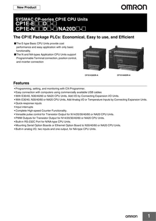
  • 1. 1 New Product SYSMAC CP-series CP1E CPU Units CP1E-E@@D@-@ CP1E-N@@D@-@/NA20D@-@ The CP1E Package PLCs: Economical, Easy to use, and Efficient ■The E-type Basic CPU Units provide cost performance and easy application with only basic functionality. ■The N and NA-types Application CPU Units support Programmable Terminal connection, position control, and inverter connection Features • Programming, setting, and monitoring with CX-Programmer. • Easy connection with computers using commercially available USB cables • With E30/40, N30/40/60 or NA20 CPU Units, Add I/O by Connecting Expansion I/O Units. • With E30/40, N30/40/60 or NA20 CPU Units, Add Analog I/O or Temperature Inputs by Connecting Expansion Units. • Quick-response inputs • Input interrupts • Complete High-speed Counter Functionality. • Versatile pulse control for Transistor Output for N14/20/30/40/60 or NA20 CPU Units. • PWM Outputs for Transistor Output for N14/20/30/40/60 or NA20 CPU Units. • Built-in RS-232C Port for N/NA-type CPU Units. • Mounting Serial Option Boards or Ethernet Option Board to N30/40/60 or NA20 CPU Units. • Built-in analog I/O, two inputs and one output, for NA-type CPU Units. CP1E-E20DR-A CP1E-N40DR-A
  • 2. CP1E-E@@D@-@ CP1E-N@@D@-@/NA20D@-@ 2 System Configuration Basic System Configuration Using an E-type CPU Unit Basic System Configuration Using an N/NA-type CPU Unit Personal computer CP1E-E30DR-A CP1E-E40DR-A CP1E-E10D@-@ CP1E-E14DR-A CP1E-E20DR-A Support Software CX-Programmer IBM PC/AT or equivalent CP1E CPU Unit Expansion I/O Units Expansion Units 20 or 40 I/O Points 8 inputs 8 outputs 16 outputs 32 outputs Up to 3 Units can be connected CP1W-CN811 CP1E CPU Unit Expansion Units and Expansion I/O Units I/O Connecting Cable When a two level layout is created by expansion and distance is required DIN Track Analog I/O Analog inputs Analog outputs Temperature sensors CompoBus/S I/O Link Unit CP1E PLCs are supported by CP1W-CIF41 version 2.0 or higher. CP1E-N30D - CP1E-N40D - CP1E-N60D - CP1E-NA20D - CP1E-N14D - CP1E-N20D - CP1E CPU Unit Expansion I/O Units Expansion Units 20 or 40 I/O Points 8 inputs 8 outputs 16 outputs 32 outputs Analog I/O Analog inputs Analog outputs Temperature sensors CompoBus/S I/O Link Unit Up to 3 Units can be connected DIN Track CP1W-CN811 CP1E CPU Unit Expansion Units and Expansion I/O Units I/O Connecting Cable Personal computer IBM PC/AT or equivalent Built in RS-232C COMM RS-232C Option Board CP1W-CIF01 COMM RS-422A/485 Option Board CP1W-CIF11 CP1W-CIF12 Or Or Battery CP1W-BAT01 When a two level layout is created by expansion and distance is required (NT Link/HOST Link) General component (No-protocol mode) (Modbus-RTU) CP-series PLC or CJ1M PLC (Serial PLC Link) Host computer (Host Link) Programmable Terminal (PT) *The CP1W-DAM01 LCD Option Board can not be used. Inverter Support Software CX-Programmer Ethernet Option Board CP1W-CIF41 IP ADDRESS: SUBNET MASK: COMM ERR 10BASE-T 100BASE-TX
  • 3. CP1E-E@@D@-@ CP1E-N@@D@-@/NA20D@-@ 3 Ordering Information International Standards • The standards are abbreviated as follows: U: UL, U1: UL (Class I Division 2 Products for Hazardous Locations), C: CSA, UC: cULus, UC1: cULus (Class I Division 2 Products for Hazardous Locations), CU: cUL, N: NK, L: Lloyd, and CE: EC Directives. • Contact your OMRON representative for further details and applicable conditions for these standards. E-type CP1E CPU Units (Basic Models) Note: There are no accessories included with E-type CP1E CPU Units. A Battery (CP1W-BAT01) cannot be used. Product name Specifications External power supply (24 VDC) (A) Current consumption (A) Model Standards Power Supply Inputs Outputs Output type Program capacity Data memory capacity 5 V 24 V E-type CPU Units with 10 I/O Points 100 to 240 VAC 6 4 Relay 2K steps 2K words -- 0.08 0.04 CP1E-E10DR-A UC1, N, L, CE Transistor (sinking) -- 0.11 -- CP1E-E10DT-A Transistor (sourcing) -- 0.11 -- CP1E-E10DT1-A 24 VDC Relay -- 0.08 0.04 CP1E-E10DR-D Transistor (sinking) -- 0.11 -- CP1E-E10DT-D Transistor (sourcing) -- 0.11 -- CP1E-E10DT1-D E-type CPU Units with 14 I/O Points 100 to 240 VAC 8 6 Relay 2K steps 2K words -- 0.16 0.07 CP1E-E14DR-A UC1, N, L, CE E-type CPU Units with 20 I/O Points 100 to 240 VAC 12 8 Relay 2K steps 2K words -- 0.17 0.08 CP1E-E20DR-A UC1, N, L, CE E-type CPU Units with 30 I/O Points 100 to 240 VAC 18 12 Relay 2K steps 2K words 0.30 0.17 0.07 CP1E-E30DR-A UC1, N, L, CE E-type CPU Units with 40 I/O Points 100 to 240 VAC 24 16 Relay 2K steps 2K words 0.30 0.17 0.09 CP1E-E40DR-A UC1, N, L, CE
  • 4. CP1E-E@@D@-@ CP1E-N@@D@-@/NA20D@-@ 4 N/NA-type CP1E CPU Units (Application Models) Product name Specifications External power supply (24 VDC) (A) Current consumption (A) Model Standards Power Supply Inputs Outputs Output type Program capacity Data memory capacity 5 V 24 V N-type CPU Units with 14 I/O Points 100 to 240 VAC 8 6 Relay 8K steps 8K words -- 0.17 0.07 CP1E-N14DR-A UC1, N, L, CE Transistor (sinking) -- 0.22 0.02 CP1E-N14DT-A Transistor (sourcing) -- 0.22 0.02 CP1E-N14DT1-A 24 VDC Relay -- 0.17 0.07 CP1E-N14DR-D Transistor (sinking) -- 0.22 0.02 CP1E-N14DT-D Transistor (sourcing) -- 0.22 0.02 CP1E-N14DT1-D N-type CPU Units with 20 I/O Points 100 to 240 VAC 12 8 Relay 8K steps 8K words -- 0.18 0.08 CP1E-N20DR-A UC1, N, L, CE Transistor (sinking) -- 0.23 0.02 CP1E-N20DT-A Transistor (sourcing) -- 0.23 0.02 CP1E-N20DT1-A 24 VDC Relay -- 0.18 0.08 CP1E-N20DR-D Transistor (sinking) -- 0.23 0.02 CP1E-N20DT-D Transistor (sourcing) -- 0.23 0.02 CP1E-N20DT1-D N-type CPU Units with 30 I/O Points 100 to 240 VAC 18 12 Relay 8K steps 8K words 0.30 0.21 0.07 CP1E-N30DR-A UC1, N, L, CE Transistor (sinking) 0.30 0.27 0.02 CP1E-N30DT-A Transistor (sourcing) 0.30 0.27 0.02 CP1E-N30DT1-A 24 VDC Relay -- 0.21 0.07 CP1E-N30DR-D Transistor (sinking) -- 0.27 0.02 CP1E-N30DT-D Transistor (sourcing) -- 0.27 0.02 CP1E-N30DT1-D N-type CPU Units with 40 I/O Points 100 to 240 VAC 24 16 Relay 8K steps 8K words 0.30 0.21 0.09 CP1E-N40DR-A UC1, N, L, CE Transistor (sinking) 0.30 0.31 0.02 CP1E-N40DT-A Transistor (sourcing) 0.30 0.31 0.02 CP1E-N40DT1-A 24 VDC Relay -- 0.21 0.09 CP1E-N40DR-D Transistor (sinking) -- 0.31 0.02 CP1E-N40DT-D Transistor (sourcing) -- 0.31 0.02 CP1E-N40DT1-D N-type CPU Units with 60 I/O Points 100 to 240 VAC 36 24 Relay 8K steps 8K words 0.30 0.21 0.13 CP1E-N60DR-A UC1, N, L, CE Transistor (sinking) 0.30 0.31 0.02 CP1E-N60DT-A Transistor (sourcing) 0.30 0.31 0.02 CP1E-N60DT1-A 24 VDC Relay -- 0.21 0.13 CP1E-N60DR-D Transistor (sinking) -- 0.31 0.02 CP1E-N60DT-D Transistor (sourcing) -- 0.31 0.02 CP1E-N60DT1-D
  • 5. CP1E-E@@D@-@ CP1E-N@@D@-@/NA20D@-@ 5 Note: There are no accessories included with N/NA-type CP1E CPU Units. RS-232C connectors for the built-in RS-232C port and the Battery (CP1W-BAT01) are not included. NA-type CPU Units with 20 I/O Points (Built-in analog) 100 to 240 VAC 12 (Built-in analog inputs: 2) 8 (Built-in analog outputs: 1) Relay 8K steps 8K words 0.30 0.18 0.11 CP1E-NA20DR-A UC1, N, L, CE 24 VDC Transistor (sinking) -- 0.23 0.09 CP1E-NA20DT-D Transistor (sourcing) -- 0.23 0.09 CP1E-NA20DT1-D Battery Set For N/NA-type CP1E CPU Units Note: Mount a Battery to an N/NA-type CPU Unit if the data in the following areas must be backed up for power interruptions. • DM Area (D) (except backed up words in the DM Area), Holding Area (H), Counter Completion Flags (C), Counter Present Values (C), Auxiliary Area (A), and Clock Function (Use batteries within two years of manufacture.) CP1W-BAT01 CE Product name Specifications External power supply (24 VDC) (A) Current consumption (A) Model Standards Power Supply Inputs Outputs Output type Program capacity Data memory capacity 5 V 24 V
  • 6. CP1E-E@@D@-@ CP1E-N@@D@-@/NA20D@-@ 6 Options (for CP1E N30/40/60 or NA20 CPU Units) The Options cannot be used for CP1E N14/20 CPU Units and all E-type CPU Units. Note: It is not possible to use a CP-series Ethernet Option Board version 1.0 (CP1W-CIF41), LCD Option Board (CP1W-DAM01), or Memory Card (CP1W-ME05M) with a CP1E CPU Unit. Programming Devices Note: 1. The E20, E30, E40, N20, N30 and N40 CPU Units are supported by CX-Programmer version 8.2 or higher. The E10, E14, N14, N60, and NA20 CPU Units are supported by CX-Programmer version 9.03 or higher. When Micro PLC Edition CX-Programmer is used, you need version 9.03 or higher. 2. The CX-One and CX-One Lite cannot be simultaneously installed on the same computer. * 1 Multi licenses are available for the CX-One (3, 10, 30 or 50 licenses). * 2 The CX-One is also available on CD (CXONE-AL@@C-V4). The following tables lists the Support Software that can be installed from CX-One Note: For details, refer to the CX-One Catalog (Cat. No. R134). Product name Specifications Model Standards RS-232C Option Board One RS-232C Option Board can be mounted to the Option Board slot. For CP1E N30/40/60 or NA20 CPU Units only. One RS-232C connector is included. CP1W-CIF01 UC1, N, L, CERS-422A/485 Option Board One RS-422A/485 Option Board can be mounted to the Option Board slot. For CP1E N30/40/60 or NA20 CPU Units only. CP1W-CIF11 RS-422A/485 Isolated-type Option Board CP1W-CIF12 UC1, N, L, CE Ethernet Option Board One Ethernet Option Board can be mounted to the Option Board slot. CP1E CPU Units are supported by CP1W-CIF41 version 2.0 or higher. For CP1E N30/40/60 or NA20 CPU Units only. When using CP1W-CIF41, CX-Programmer version 9.12 or higher is required. CP1W-CIF41 UC1, N, L, CE Product name Specifications Model StandardsNumber of licenses Media FA Integrated Tool Package CX-One Lite Ver.4.@ CX-One Lite is a subset of the complete CX-One package that provides only the Support Software required for micro PLC applications. CX-One Lite runs on the following OS. Windows 2000 (Service Pack 4 or higher), XP, Vista, or 7 Note: Except for 64-bit version. CX-One Lite Ver. 4.@ includes Micro PLC Edition CX- Programmer Ver.9.@. 1 license CD CXONE-LT01C-V4 -- FA Integrated Tool Package CX-One Package Ver. 4.@ CX-One is a comprehensive software package that integrates Support Software for OMRON PLCs and components. CX- One runs on the following OS. OS: Windows 2000 (Service Pack 4 or higher), XP, Vista, or 7 Note: Except for 64-bit version. CX-One Ver. 4.@ includes CX-Programmer Ver. 9.@. 1 license *1 DVD*2 CXONE-AL01D-V4 -- Support Software in CX-One CX-One Lite Ver.4.@ CX-One Ver.4.@ Support Software in CX-One CX-One Lite Ver.4.@ CX-One Ver.4.@ Micro PLC Edition CX-Programmer Ver.9.@ Yes No CX-Drive Ver.1.@ Yes Yes CX-Programmer Ver.9.@ No Yes CX-Process Tool Ver.5.@ No Yes CX-Integrator Ver.2.@ Yes Yes Faceplate Auto-Builder for NS Ver.3.@ No Yes Switch Box Utility Ver.1.@ Yes Yes CX-Designer Ver.3.@ Yes Yes CX-Protocol Ver.1.@ No Yes NV-Designer Ver.1.@ Yes Yes CX-Simulator Ver.1.@ Yes Yes CX-Thermo Ver.4.@ Yes Yes CX-Position Ver.2.@ No Yes CX-ConfiguratorFDT Ver.1.@ Yes Yes CX-Motion-NCF Ver.1.@ No Yes CX-FLnet Ver.1.@ No Yes CX-Motion-MCH Ver.2.@ No Yes Network Configurator Ver.3.@ Yes Yes CX-Motion Ver.2.@ No Yes CX-Server Ver.4.@ Yes Yes
  • 7. CP1E-E@@D@-@ CP1E-N@@D@-@/NA20D@-@ 7 Expansion I/O Units and Expansion Units (for CP1E E30/40, N30/40/60, or NA20 CPU Units) CP1E E10/14/20 or N14/20 CPU Units do not support Expansion I/O Units and Expansion Units. I/O Connecting Cable Note: An I/O Connecting Cable (approx. 6 cm) for horizontal connection is provided with CP1W Expansion I/O Units and Expansion Units. Unit type Product name Specifications Current consumption (A) Model Standards Inputs Outputs Output type 5 V 24 V CP1W Expansion I/O Units Input Unit 8 -- -- 0.018 -- CP1W-8ED U, C, N, L, CEOutput Units -- 8 Relay 0.026 0.044 CP1W-8ER Transistor (sinking) 0.075 -- CP1W-8ET Transistor (sourcing) 0.075 -- CP1W-8ET1 -- 16 Relay 0.042 0.090 CP1W-16ER N, L, CE Transistor (sinking) 0.076 -- CP1W-16ET Transistor (sourcing) 0.076 -- CP1W-16ET1 -- 32 Relay 0.049 0.131 CP1W-32ER N, L, CE Transistor (sinking) 0.113 -- CP1W-32ET Transistor (sourcing) 0.113 -- CP1W-32ET1 I/O Units 12 8 Relay 0.103 0.044 CP1W-20EDR1 U, C, N, L, CE Transistor (sinking) 0.130 -- CP1W-20EDT Transistor (sourcing) 0.130 -- CP1W-20EDT1 24 16 Relay 0.080 0.090 CP1W-40EDR N, L, CE Transistor (sinking) 0.160 -- CP1W-40EDT Transistor (sourcing) 0.160 -- CP1W-40EDT1 CP1W Expansion Units Analog Input Unit 4 analog inputs Input range: 0 to 5 V, 1 to 5 V, 0 to 10 V, ±10 V, 0 to 20 mA, or 4 to 20 mA. Resolution: 1/6000 0.100 0.090 CP1W-AD041 UC1, N, L, CE Analog Output Unit 2 analog outputs Output range: 1 to 5 V, 0 to 10 V, ±10 V, 0 to 20 mA, or 4 to 20 mA. Resolution: 1/6000 0.040 0.095 CP1W-DA021 UC1, CE 4 analog outputs Output range: 1 to 5 V, 0 to 10 V, ±10 V, 0 to 20 mA, or 4 to 20 mA. Resolution: 1/6000 0.080 0.124 CP1W-DA041 UC1, N, L, CE Analog I/O Unit 2 analog inputs and 1 analog output Input range: 0 to 5 V, 1 to 5 V, 0 to 10 V, ±10 V, 0 to 20 mA, or 4 to 20 mA. Output range: 1 to 5 V, 0 to 10 V, ±10 V, 0 to 20 mA, or 4 to 20 mA. Resolution: 1/6000 0.083 0.110 CP1W-MAD11 U, C, N, L, CE Temperature Sensor Unit 2 temperature sensor inputs Sensor type: Thermocouple (J or K) 0.040 0.059 CP1W-TS001 4 temperature sensor inputs Sensor type: Thermocouple (J or K) 0.040 0.059 CP1W-TS002 2 temperature sensor inputs Sensor type: Platinum resistance thermometer (Pt100 or JPt100) 0.054 0.073 CP1W-TS101 4 temperature sensor inputs Sensor type: Platinum resistance thermometer (Pt100 or JPt100) 0.054 0.073 CP1W-TS102 CompoBus/S I/O Link Unit CompoBus/S slave 8 inputs and 8 outputs 0.029 -- CP1W-SRT21 Product name Specifications Model Standards I/O Connecting Cable 80 cm (for CP1W Expansion I/O Units and Expansion Units) Only one I/O Connecting Cable can be used in each PLC. CP1W-CN811 UC1, N, L, CE
  • 8. CP1E-E@@D@-@ CP1E-N@@D@-@/NA20D@-@ 8 General Specifications * 1 Total of 110 mm with mounting brackets. * 2 Excluding cables. * 3 Use the external power supply to power input devices. Do not use it to drive output devices. * 4 This is the rated value for the maximum system configuration. Use the following formula to calculate power consumption for CPU Units with DC power. Formula: DC power consumption = (5V current consumption ✕ 5 V/70% (internal power efficiency) + 24V current consumption) ✕ 1.1(current fluctuation factor) The above calculation results show that a DC power supply with a greater capacity is required. Type AC power supply models DC power supply models Model CP1E-@@@D@-A CP1E-@@@D@-D Enclosure Mounted in a panel Dimensions (H × D × W) CPU Unit with 10 I/O points (CP1E-E10D@-@): 90mm *1 ×85mm *2 × 66 mm CPU Unit with 14 or 20 I/O points (CP1E-@14D@-@/@20D@-@): 90mm *1 × 85mm *2 × 86 mm CPU Unit with 30 I/O points (CP1E-@30D@-@): 90mm *1 × 85mm *2 × 130 mm CPU Unit with 40 I/O points (CP1E-@40D@-@): 90mm *1 × 85mm *2 × 150 mm CPU Unit with 60 I/O points (CP1E-N60D@-@): 90mm *1 ×85mm *2 × 195 mm CPU Unit with 20 I/O points and built-in analog (CP1E-NA20D@-@): 90mm *1 ×85mm *2 × 130 mm Weight CPU Unit with 10 I/O points (CP1E-E10D@-@): 300g max. CPU Unit with 14 I/O points (CP1E-@14D@-@): 360g max. CPU Unit with 20 I/O points (CP1E-@20D@-@): 370g max. CPU Unit with 30 I/O points (CP1E-@30D@-@): 600g max. CPU Unit with 40 I/O points (CP1E-@40D@-@): 660g max. CPU Unit with 60 I/O points (CP1E-N60D@-@): 850g max. CPU Unit with 20 I/O points and built-in analog (CP1E-NA20D@-@): 680g max. Electrical specifications Supply voltage 100 to 240 VAC 50/60 Hz 24 VDC Operating voltage range 85 to 264 VAC 20.4 to 26.4 VDC Power consumption 15 VA/100 VAC max. 25 VA/240 VAC max. (CP1E-E10D@-A/@14D@-A/@20D@-A) 9 W max. (CP1E-E10D@-D) 13 W max. (CP1E-N14D@-D/N20D@-D) 50 VA/100 VAC max. 70 VA/240 VAC max. (CP1E-NA20D@-A/@30D@-A/@40D@-A/N60D@-A) 20 W max. (CP1E-NA20D@-D/N30D@-D/N40D@-D/N60D@-D) *4 Inrush current 120 VAC, 20 A for 8 ms max. for cold start at room temperature 240 VAC, 40 A for 8 ms max. for cold start at room temperature 24 VDC, 30 A for 20 ms max. for cold start at room temperature External power supply *3 Not provided. (CP1E-E10D@-A/@14D@-A/@20D@-A) 24 VDC, 300 mA (CP1E-NA20D@-A/@30D@-A/@40D@-A/N60D@-A) Not provided Insulation resistance 20 MΩ min. (at 500 VDC) between the external AC terminals and GR terminals Except between DC primary current and DC secondary current Dielectric strength 2,300 VAC 50/60Hz for 1 min between AC external and GR terminals Leakage current: 5 mA max. Except between DC primary current and DC secondary current Power OFF detection time 10 ms min. 2 ms min. Application environment Ambient operating temperature 0 to 55 °C Ambient humidity 10% to 90% Atmosphere No corrosive gas. Ambient storage temperature -20 to 75 °C (excluding battery) Altitude 2,000 m max. Pollution degree 2 or less: Conforms to JIS B3502 and IEC 61131-2. Noise resistance 2 kV on power supply line (Conforms to IEC61000-4-4.) Overvoltage category Category II: Conforms to JIS B3502 and IEC 61131-2. EMC Immunity Level Zone B Vibration resistance Conforms to JIS 60068-2-6. 5 to 8.4 Hz with 3.5-mm amplitude, 8.4 to 150 Hz Acceleration of 9.8 m/s2 for 100 min in X, Y, and Z directions (10 sweeps of 10 min each = 100 min total) Shock resistance Conforms to JIS 60068-2-27. 147 m/s2 , 3 times in X, Y, and Z directions Terminal block Fixed (not removable) Terminal screw size M3 Applicable standards Conforms to EC Directive Grounding method Ground to 100 Ω or less.
  • 9. CP1E-E@@D@-@ CP1E-N@@D@-@/NA20D@-@ 9 Performance Specifications Item CP1E-@@D@-@ CP1E-N@@D@-@ CP1E-NA@@D@-@ Program capacity 2 K steps (8 Kbytes) including the symbol table, comments, and program indices of the CX-Programmer 8 K steps (32 Kbytes) including the symbol table, comments, and program indices of the CX-Programmer Control method Stored program method I/O control method Cyclic scan with immediate refreshing Program language Ladder diagram Instructions Approximately 200 Processing speed Overhead processing time 0.4 ms Instruction execution times Basic instructions (LD): 1.19 µs min. Special instructions (MOV): 7.9 µs min. Number of CP1W-series Expansion Units connected CP1E-E10D@-@/@14D@-@/@20D@-@: None CP1E-@30D@-@/@40D@-@/N60D@-@/NA20D@-@: 3 units Maximum number of I/O points CP1E-E10D@-@ : 10 CP1E-@14D@-@ : 14 CP1E-@20D@-@ : 20 CP1E-@30D@-@ : 150 (30 built in, 40 × 3 expansion) CP1E-@40D@-@ : 160 (40 built in, 40 × 3 expansion) CP1E-N60D@-@ : 180 (60 built in, 40 × 3 expansion) CP1E-NA20D@-@: 140 (20 built in, 40 × 3 expansion) Built-in I/O CP1E-E10D@-@ : 10 (6 inputs, 4 outputs) CP1E-@14D@-@ : 14 (8 inputs, 6 outputs) CP1E-@20D@-@ : 20 (12 inputs, 8 outputs) CP1E-@30D@-@ : 30 (18 inputs, 12 outputs) CP1E-@40D@-@ : 40 (24 inputs, 16 outputs) CP1E-N60D@-@ : 60 (36 inputs, 24 outputs) CP1E-NA20D@-@: 20 (12 inputs, 8 outputs) Built-in input functions High-speed counters High-speed counter mode/ maximum frequency Incremental Pulse Inputs 10 kHz: 6 counters 5 counters (only for 10 I/O points) Up/Down Inputs 10 kHz: 2 counters Pulse + Direction Inputs 10 kHz: 2 counters Differential Phase Inputs (4x) 5 kHz: 2 counters Incremental Pulse Inputs 100 kHz: 2 counters,10 kHz: 4 counters Up/Down Inputs 100 kHz: 1 counters,10 kHz: 1 counters Pulse + Direction Inputs 100 kHz: 2 counters Differential Phase Inputs (4x) 50 kHz: 1 counter, 5 kHz: 1 counter Counting mode Linear mode Ring mode Count value 32 bits Counter reset modes Phase Z and software reset (excluding increment pulse input) Software reset Control method Target Matching Range Comparison Input interrupts 6 inputs (4 inputs only for 10 I/O points) Interrupt input pulse width: 50 µs min. Quick-response Inputs 6 inputs (4 inputs only for 10 I/O points) Input pulse width: 50 µs min. Normal input Input constants Delays can be set in the PLC Setup (0 to 32 ms, default: 8 ms). Set values: 0, 1, 2, 4, 8, 16, or 32 ms Built-in output functions Pulse outputs (Models with transistor outputs only) Pulse output method and output frequency Pulse output function not included Pulse + Direction Mode 1 Hz to 100 kHz: 2 outputs Output mode Continuous mode (for speed control) Independent mode (for position control) Number of output pulses Relative coordinates: 0000 0000 to 7FFF FFFF hex (0 to 2147483647) Absolute coordinates: 8000 0000 to 7FFF FFFF hex (-2147483647 to 2147483647) Acceleration/ deceleration curves Trapezoidal acceleration and deceleration (Cannot perform S-curve acceleration and deceleration.) Changing SVs during instruction execution Only target position can be changed. Origin searches Included Pulse outputs (Models with transistor outputs only) Frequency PWM output function not included 2.0 to 6,553.5 Hz (in increments of 0.1 Hz) with 1 output or 2 Hz to 32,000 Hz (in increments of 1 Hz) with 1 output Duty factor 0.0% to 100.0% (in increments of 0.1%) Accuracy: +1%/-0% at 2 Hz to 10,000 Hz and +5%/-0% at 10,000 Hz to 32,000 kHz Output mode Continuous Mode Built-in analog Analog input Analog function not included Setting range: 0 to 6,000 (2 channels only for NA-type) Analog output Setting range: 0 to 6,000 (1 channels only for NA-type) Analog adjusters 2 adjusters (Setting range: 0 to 255)
  • 10. CP1E-E@@D@-@ CP1E-N@@D@-@/NA20D@-@ 10 Item CP1E-E@@D@-@ CP1E-N@@D@-@ CP1E-NA@@D@-@ Communications B-type Peripheral USB Port Conforming to USB 2.0 B type connector Transmission distance 5 m max. Built-in RS-232C port No built-in RS-232C port Interface: Conforms to EIA RS-232C. Communications method Half duplex synchronization Start-stop Baud rate 1.2, 2.4, 4.8, 9.6, 19.2, 38.4, 57.6, or 115.2 kbps Transmission distance 15 m max. Supported protocol • Host Link • 1:N NT Link • No-protocol mode • Serial PLC Links (master, slave) • Modbus-RTU Easy Master Serial Option port Option Board cannot be mounted. 1 port (Option Board can be mounted only to N30/40/ 60 and NA20 CPU Units.) Mountable Option Boards • One RS-232C port: CP1W-CIF01 • One RS-422A/485 port (not isolated): CP1W-CIF11 • One RS-422A/485 port (isolated): CP1W-CIF12 • One Ethernet port: CP1W-CIF41 Communications method Depends on Option Board. synchronization Depends on Option Board. Baud rate 1.2, 2.4, 4.8, 9.6, 19.2, 38.4, 57.6, or 115.2 kbps Compatible protocols • Host Link • 1:N NT Link • No-protocol mode • Serial PLC Links (master, slave) • Modbus-RTU Easy Master Number of tasks 17 • One cyclic execution task • One scheduled interrupt task (always interrupt task 1) • Six input interrupt tasks (interrupt tasks 2 to 7) • Sixteen high-speed counter interrupt tasks (interrupt tasks 1 to 16) Maximum subroutine number 128 Maximum jump number 128 Scheduled interrupt tasks 1 interrupt task Clock Clock function not included. The time of error occurrence displays 01-01-01 01:01:01 Sunday Included. Accuracy (monthly deviation): -4.5 min to -0.5 min at ambient temperature of 55o C, -2.0 min to +2.0 min at ambient temperature of 25o C, -2.5 min to +1.5 min at ambient temperature of 0o C Memory backup Built-in EEPROM Ladder programs and parameters are automatically saved to built-in EEPROM A section of the Data Memory Area can be saved to the built-in EEPROM. Battery backup With CP1W-BAT01 Battery (Sold separately) Battery cannot be mounted. CP1W-BAT01 can be used. Maximum battery service life: 5 years Backup Time Guaranteed value (ambient temperature: 55o C): 13,000 hours (approx. 1.5 years) Effective value (ambient temperature: 25o C): 43,000 hours (approx. 5 years) CIO Area Input Bits 1,600 bits (100 words): CIO 0.00 to CIO 99.15 (CIO 00 to CIO 99) Output Bits 1,600 bits (100 words): CIO 100.00 to CIO 199.15 (CIO 100 to CIO 199) Serial PLC Link Words 1,440 bits (90 words): CIO 200.00 to CIO 289.15 (words CIO 200 to CIO 289) Work Area (W) 1,600 bits (100 words): W0.00 to W99.15 (W0 to W99) Holding Area (H) 800 bits (50 words): H0.00 to H49.15 (H0 to H49) Bits in this area maintain their ON/OFF status when operating mode is changed. Auxiliary Area (A) Read-only: 7,168 bits (448 words) A0 to A447 Read/write: 4,896 bits (306 words) in words A448 to A753 Temporary Relay Area (TR) (TR Area) 16 bits: TR0 to TR15 Timer Area (T) 256 timer numbers (T0 to T255 (separate from counters)) Counter Area (C) 256 counter numbers (C0 to C255 (separate from timers)) Data Memory Area (D) 2 Kwords: D0 to D2047 Of these, 1,500 words can be saved to the backup memory (built-in EEPROM) using settings in the Auxiliary Area. 8 Kwords: D0 to D8191 Of these, 7,000 words can be saved to the backup memory (built-in EEP-ROM) using settings in the Auxiliary Area Operating modes PROGRAM mode: Program execution is stopped. Preparations can be executed prior to program execution in this mode. MONITOR mode: Programs are executed. Some operations, such as online editing, and changes to present values in I/O memory, are enabled in this mode. RUN mode: Programs are executed. This is the normal operating mode.
  • 11. CP1E-E@@D@-@ CP1E-N@@D@-@/NA20D@-@ 11 Function Specifications Function Function description Cycle time management Minimum cycle time Makes the cycle time consistent. Monitoring the cycle time Monitors the cycle time. CPU Unit built-in functions Inputs High-speed counter inputs High-speed pulse inputs High-speed pulses from devices such as a rotary encoder are counted. The counted values are stored in the Auxiliary Area. Interrupt tasks can be executed when target is reached or by range comparison. Input pulse frequency measurement The frequency of pulses input by the PRV instruction is measured. Interrupt inputs Relevant interrupt tasks are executed during the cycle when the CPU Unit built-in inputs turn ON or turn OFF. Quick-response inputs Inputs can be read without being affected by cycle time. Use the quick-response inputs to read signals shorter than the cycle time. Normal inputs I/O refreshing Cyclic refreshing The CPU Unit’s built-in I/O are cyclically refreshed. Immediate refreshing I/O refreshing by immediate refreshing instructions Input response times Input constants can be set for Basic I/O Units. The response time can be increased to reduce the effects of chattering and noise at input contacts. The response time can be decreased to enable detecting shorter input pulses. Outputs Pulse outputs (Models with transistor outputs only) Pulse control A pulse signal is output and positioning or speed control is performed with a servo driver that accepts a pulse input. Continuous mode for speed control or independent mode for position control can be used. There are functions for changing to positioning during speed control and for changing the target value during positioning. Origin positioning Origin searches and origin returns PWM outputs (Models with transistor outputs only) Pulses for which the duty ratio (ratio between ON time and OFF time during one pulse cycle) can be set are output. Normal outputs Load OFF function All of the outputs on the CPU Unit’s I/O can be turned OFF when an error occurs in RUN or MONITOR mode. Built-in analog Analog input Convert analog signal into digital value range from 0 to 6,000. Analog output Convert digital value range from 0 to 6,000 into analog signal. Expansion I/O Units and Expansion Units Functions supported by both Expansion I/O Unit and Expansion Unit I/O refreshing Cyclic refreshing The Expansion I/O Units and Expansion Units are cyclically refreshed. Refreshing by IORF I/O refreshing by IORF instruction Load OFF function All of the outputs on Expansion I/O Units and Expansion Units are turned OFF (0000 hex) when an error occurs in RUN or MONITOR mode. Expansion I/O Units Input response times The response time can be increased to reduce the effects of chattering and noise at input contacts. The response time can be decreased to enable detecting shorter input pulses. Expansion Units Unit error detection Errors in Expansion Units are detected. The CPU Unit is notified that the Expansion Unit stopped due to an error. Memory management functions Holding I/O memory when changing operating modes The status of I/O memory can be held when the operating mode is changed. The forced-set/reset status can be held when the operating mode is changed. Automatic backup to the backup memory (built-in EEPROM) Automatic backup of ladder programs and parameter area to the backup memory (built-in EEPROM) Communic ations Peripheral USB port Peripheral bus (toolbus) For communications with programming device (CX-Programmer). Serial port (N/NA-type only) -- Host Link (SYSWAY) communications Host Link commands can be sent from a PT or a computer to read/write I/O memory, and perform other operations for PLC. No-protocol communications I/O instructions for communications ports (TXD/RXD instructions) can be used for data transfer with peripheral devices such as bar code readers. NT Link communications I/O memory in the PLC can be allocated and directly linked to various PT functions, including status control areas, status notification areas, touch switches, lamps, memory tables, and other objects. Serial PLC Links Up to ten words per Unit can be shared by up to nine CPU Units, including one Polling Unit and eight Polled Units. Note: Programmable Terminal (PT) cannot be connected. Modbus-RTU Easy Master function Modbus-RTU commands are sent by the Modbus-RTU Master function. Modbus slaves, such as inverters, can be easily controlled with serial communications. Interrupt Scheduled interrupts Tasks can be executed at a specified interval (1.0 ms min., Unit: 0.1 ms). Interrupt inputs Interrupt tasks are processed when the built-in input turns ON or OFF. High-speed counter interrupts This function counts input pulses with the CPU Unit’s built-in high-speed counter and executes an interrupt task when the count reaches the preset value or falls within a preset range (target value or zone comparison).
  • 12. CP1E-E@@D@-@ CP1E-N@@D@-@/NA20D@-@ 12 Function Function description Power supply management Memory protection Holding Area data, DM Area data, Counter Completion Flags, and counter present values are held even when power is turned OFF. This function can be used only with an N/NA-type CPU Unit and only when the Battery Set (sold separately) is mounted. Number of power interruptions counter The number of times power has been interrupted is counted. Debugging Online editing The program can be changed during operation in MONITOR mode or PROGRAM mode. Force-set/reset Specified bits can be set or reset. Differentiate monitoring ON/OFF changes in specified bits can be monitored. Storing the stop position at errors The location and task number where execution stopped for a program error is recorded. Program check The programs can be checked for items such as no END instruction and FALS/FAL errors at startup. Self-diagnosis and restoration Error Log Details and the time of occurrence of error codes predefined by the CPU Unit are stored. CPU error detection CPU Unit WDT errors are detected. User-defined failure diagnosis Errors can be generated for user-specified conditions: Non-fatal errors (FAL) and fatal errors (FALS). Load OFF function The built-in outputs, Expansion I/O Unit outputs, and Expansion Unit outputs are turned OFF. Non-fatal error detection System FAL error detection (User-defined non-fatal error) This function generates a non-fatal (FAL) error when the user-defined conditions are met in program. Backup memory error detection This function detects when data in the backup memory (built-in EEPROM) that stores the ladder program is corrupted. PLC Setup error detection This function detects setting errors in the PLC Setup. Option Board errors This function detects when the Option Board is malfunctioning or disconnected. Battery error detection (N/NA-type CPU Units only) This function detects when the battery voltage is low or the battery is disconnected. Note: This function is valid only when a battery is mounted and the Do not detect battery error Check Box is cleared in the PLC Setup. Built-in analog error This function detects when a built-in analog I/O error occurs and stops the operation of built- in analog I/O. Fatal Error Detection Memory error detection This function detects errors that occur in memory of the CPU Unit. I/O bus error detection This function detects errors that occur during data transfer between the CPU Unit and another Unit. Too Many I/O Points Error Detection This function detects when more than the maximum number of CP1W Expansion I/O Units and Expansion Units are connected to the PLC. Program error detection This function detects when there is an error in the program. See the following for details. Instruction processing error detection This function detects an error when the given data value is invalid when executing an instruction, or execution of instruction between tasks was attempted. Indirect DM addressing BCD error This function detects an error when an indirect DM address in BCD mode is not BCD. Illegal area access error detection This function detects an error when an attempt is made to access an illegal area with an instruction operand. No END error detection This function detects an error when there is no END instruction at the end of the program. Task error detection The execution condition for an interrupt task was met but there is no interrupt task with the specified number. overflow error detection This function detects an error when too many differentiated instructions are entered or deleted during online editing (131,072 times or more). Invalid instruction error detection This function detects an error when an attempt is made to execute an instruction that is not defined in the system. User program area overflow error detection This function detects an error when instruction data is stored after the last address in user program area. Cycle time exceeded error detection This function monitors the cycle time (10 to 1,000 ms) and stops the operation when the set value is exceeded. System FALS error detection (user-defined fatal error) This function generates a fatal (FALS) error when the user-defined conditions are met in program. Maintenance Automatic online connection via network This function enables automatically connecting to the PLC online when the CX-Programmer is directly connected by a serial connection (peripheral USB port or serial port). Security functions Read protection using password This function protects user memory. Read protection: Set a password using the CX-Programmer. Overwrite protection is not provided. Write protection from FINS commands This function prohibits writing by using FINS commands sent over the network.
  • 13. CP1E-E@@D@-@ CP1E-N@@D@-@/NA20D@-@ 13 Internal Memory in the CPU Units CPU Unit Memory Backup Structure The internal memory in the CPU Unit consists of built-in RAM and built-in EEPROM. The built-in RAM is used as execution memory and the built- in EEPROM is used as backup memory. ●Precautions for Correct Use Create a system and write the ladder programs so that problems will not occur in the system if the data in these area may be unstable. • Data in areas such as the DM area (D), Holding Area (H), the Counter Present Values (C) and the status of Counter Completion Flags (C), which is retained by the battery, may be unstable when the power supply is turned off (Except for the DM area that are retained by the built-in EEP- ROM using the Auxilliary Area bit.) • The error log, and clock data (N/NA-type CPU Unit only) in the Auxiliary Area will become unstable. Other words and bits in the Auxiliary Area will be cleared to their default values. The built-in capacitor’s backup time varies with the ambient temperature as shown in the following graph. CPU Unit Built-in EEPROM Built-in RAM Backup memory User Program Area (Backup) PLC Setup PLC Setup DM Area DM Area User Program Area I/O Memory Areas Data is retained even if the power supply is interrupted for longer than the backup time of the built-in capacitor. Execution Memory Automatic backup Read at startup Automatic backup Read at startup Backup using bit in Auxiliary Area DM Area data read at startup If a CP1W-BAT01 Battery (sold separately) is mounted to an N/NA-type CPU Unit, which is normally backed up by a built-in capacitor, data will be backed up by the battery. Area where data is backed up even if the power supply is interrupted for longer than the back-up time of the built-in capacitor. Area where data is cleared if the power supply is interrupted for longer than the back-up time of the built-in capacitor. Backuptimeofbuilt-incapacitor 50 hours 40 hours 25 hours 20 hours 9 hours 7 hours CP1E E-type CPU Unit CP1E N/NA-type CPU Unit Ambient temperature 25 40 60
  • 14. CP1E-E@@D@-@ CP1E-N@@D@-@/NA20D@-@ 14 I/O Memory Areas Data can be read and written to I/O memory from the ladder programs. I/O memory consists of an area for I/O with external devices, user areas, and system areas. I/O Memory Areas Name No. of bits Word addresses Remarks CIO Area Input Bits 1,600 bits (100 words) CIO 0 to CIO 99 For NA-type, CIO90, CIO91 is occupied by analog input 0, 1. Output Bits 1,600 bits (100 words) CIO 100 to CIO 199 For NA-type, CIO190 is occupied by analog output 0. Serial PLC Link Words 1,440 bits (90 words) CIO 200 to CIO 289 -- Work Area (W) 1,600 bits (100 words) W0 to W99 -- Holding Area (H) 800 bits (50 words) H0 to H49 Data in this area is retained during power interruptions if a Battery Set (sold separately) is mounted to an N/NA-type CPU Unit. Data Memory Area (D) E-type CPU Unit 2K words D0 to D2047 Data in specified words of the DM Area can be retained in the built-in EEPROM in the backup memory by using a bit in the Auxiliary Area. Applicable words: D0 to D1499 (One word can be specified at a time.) N/NA-type CPU Unit 8K words D0 to D8191 Data in specified words of the DM Area can be retained in the built-in EEPROM in the backup memory by using a bit in the Auxiliary Area. Applicable words: D0 to D6999 (One word can be specified at a time.) Timer Area (T) Present values 256 T0 to T255 -- Timer Completion Flags 256 -- Counter Area (C) Present values 256 C0 to C255 Data in this area is retained during power interruptions if a Battery Set (sold separately) is mounted to an N/NA-type CPU Unit. Counter Completion Flags 256 -- Auxiliary Area (A) Read only 7168 bits (448 words) A0 to A447 Data in this area is retained during power interruptions if a Battery Set (sold separately) is mounted to an N/NA-type CPU Unit.Read-write 4,896 bits (306 words) A448 to A753 Input bits (starting from CIO 0) User Areas Holding Area (H) DM Area (D) Timer Area (T) Counter Area (C) Output bits (starting from CIO 100) Work Area (W) System Areas Auxiliary Area (A) Condition Flags Clock Pulses
  • 15. CP1E-E@@D@-@ CP1E-N@@D@-@/NA20D@-@ 15 Backing Up and Restoring DM Area Data The contents of the DM Area (D) will become unstable if the power supply is interrupted for longer than the backup time of the built-in capacitor (50 hours for an E-type CPU Unit, 40 hours for an N/NA-type CPU Unit without a Battery). The contents of the specified words in the DM Area data can be backed up from RAM to the built-in EEPROM backup memory during operation by turning ON a bit in the Auxiliary Area. The number of DM Area words to back up is specified in the Number of CH of DM for backup Box in the PLC Setup. If the Restore D0- from backup memory Check Box is selected in the PLC Setup, the backup data will automatically be restored to RAM when the power is turned back ON so that data is not lost even if power is interrupted. Conditions for Executing Backup Specified words starting from D0 in the RAM can be saved to the built-in EEPROM backup memory by turning ON A751.15. (These words are called the DM backup words and the data is called the DM backup data.) A751.15 (DM Backup Save Start Bit) can be used in any operating mode (RUN, MONITOR, or PROGRAM mode). Words That Can Be Backed Up • E-type CP1E CPU Units: D0 to D1499 • N/NA-type CP1E CPU Units: D0 to D6999 Number of Words To Back Up The number of words to back up starting from D0 is set in the Number of CH of DM for backup Box in the Startup Data Read Area in the PLC Setup. Restoring DM Backup Data to RAM When Power Is Turned ON The DM backup data can be restored to RAM when power is turned ON by selecting the Restore D0- from backup memory Check Box in the Startup Data Read Area in the PLC Setup. The DM backup data will be read from the backup memory even if the Clear retained memory area (HR/DM/CNT) Check Box is selected in the PLC Setup. D0 D(n-1) Built-in RAM CP1E CPU Unit A751.15 (DM Backup Save Start Bit) turned ON DM Area (D) Data backed up Built-in EEPROM Backup Memory DM backup data Specified number of words Specify the number of words starting from D0 in the Number of CH of DM for backup Box in the Startup Data Read Area in PLC Setup. DM backup data is restored to the RAM when power supply is turned ON again if the Restore D0- from backup memory Check Box is selected in the Startup Data Read Area in the PLC Setup. Data restored
  • 16. CP1E-E@@D@-@ CP1E-N@@D@-@/NA20D@-@ 16 Built-in Inputs Terminal Arrangements ●Input Terminal Arrangement for CPU Unit with 10 I/O Points AC power supply models DC power supply models ●Input Terminal Arrangement for CPU Unit with 14 I/O Points AC power supply models DC power supply models ●Input Terminal Arrangement for CPU Unit with 20 I/O Points AC power supply models DC power supply models ●Input Terminal Arrangement for CPU Unit with 30 I/O Points AC power supply models DC power supply models CIO 0 L1 L2/N COM 01 03 05 00 02 04NC + − COM 01 03 05 00 02 04NC CIO 0 CIO 0 L1 L2/N COM 01 03 05 07 NC NC 00 02 04 06 NC NCNC + − COM 01 03 05 07 NC NC 00 02 04 06 NC NCNC CIO 0 CIO 0 L1 L2/N COM 01 03 05 07 09 11 00 02 04 06 08 10NC CIO 0 + − COM 01 03 05 07 09 11 00 02 04 06 08 10NC L1 L2/N COM NC 01 03 05 07 09 11 00 02 04 06 08 10 01 03 05 00 02 04 CIO 0 CIO 1 + − COM NC NC 01 03 05 07 09 11 00 02 04 06 08 10 01 03 05 00 02 04 CIO 0 CIO 1
  • 17. CP1E-E@@D@-@ CP1E-N@@D@-@/NA20D@-@ 17 ●Input Terminal Arrangement for CPU Unit with 40 I/O Points AC power supply models DC power supply models ●Input Terminal Arrangement for CPU Unit with 60 I/O Points AC power supply models DC power supply models ●Input Terminal Arrangement for CPU Unit with 20 I/O Points and Built-in Analog AC power supply models DC power supply models L1 L2/N COM 01 03 05 00 02 04 07 09 11 06 08 10 01 03 05 00 02 04 07 09 11 06 08 10 CIO 0 CIO 1 + − COM NC 01 03 05 00 02 04 07 09 11 06 08 10 01 03 05 00 02 04 07 09 11 06 08 10 CIO 0 CIO 1 L1 L2/N COM 01 03 05 00 02 04 07 09 11 06 08 10 01 03 05 00 02 04 07 09 11 06 08 10 01 03 05 00 02 04 07 09 11 06 08 10 CIO 0 CIO 1 CIO 2 CIO 0 CIO 1 CIO 2 01 03 05 07 09 11 04 08 01 03 05 07 09 11 00 0000 02 04 06 08 10 01 03 05 07 09 11 02 04 06 08 10NC + − 02 COM 06 10 L1 L2/N COM COM1 01 03 05 07 09 11 00 02 04 06 08 10 I IN0 AG I IN1 VIN0 COM0 VIN1 CIO 0 CIO 90 CIO 91 CIO 0 CIO 90 CIO 91 + - COM COM1 01 03 05 07 09 11 00NC 02 04 06 08 10 I IN0 AG I IN1 VIN0 COM0 VIN1
  • 18. CP1E-E@@D@-@ CP1E-N@@D@-@/NA20D@-@ 18 Allocating Built-in Inputs to Functions Input terminals are allocated functions by setting parameters in the PLC Setup. Set the PLC Setup so that each terminal is used for only one function. CPU Unit with I/O Points Input terminal block Settings in PLC Setup Interrupt input setting on Built-in Input Tab Page High-speed counter 0 to 3 setting on Built-in Input Tab Page Origin search settings on Pulse Output 0/1 Tab Page Terminal block label Terminal number Normal Interrupt Quick Single-phase (increment pulse input) Two-phase (differential phase x4 or up/down) Two-phase (pulse/ direction) CPU Unit with 20 to 60 points CPU Unit with 14 I/O pointsNormal input Input interrupt Quick- response input 10 CIO 0 00 Normal input 0 -- -- Counter 0, increment input Counter 0, phase A or up input Counter 0, pulse input -- -- 01 Normal input 1 -- -- Counter 1, increment input Counter 0, phase B or down input Counter 1, pulse input -- -- 02 Normal input 2 Interrupt input 2 Quick-response input 2 Counter 2, increment input Counter 1, phase A or up input Counter 0, direction -- -- 03 Normal input 3 Interrupt input 3 Quick-response input 3 -- Counter 1, phase B or down input Counter 1, direction -- Pulse 0, Origin proximity input signal 04 Normal input 4 Interrupt input 4 Quick-response input 4 Counter 3, increment input Counter 0, phase Z or reset input Counter 0, reset input -- -- 05 Normal input 5 Interrupt input 5 Quick-response input 5 Counter 4, increment input Counter 1, phase Z or reset input Counter 1, reset input -- Pulse 1, Origin proximity input signal 14 06 Normal input 6 Interrupt input 6 Quick-response input 6 Counter 5, increment input -- -- Pulse 0: Origin input signal Pulse 0, Origin input signal 07 Normal input 7 Interrupt input 7 Quick-response input 7 -- -- -- Pulse 1: Origin input signal Pulse 1, Origin input signal 20 08 Normal input 8 -- -- -- -- -- -- -- 09 Normal input 9 -- -- -- -- -- -- -- 10 Normal input 10 -- -- -- -- -- Pulse 0: Origin proximity input signal -- 11 Normal input 11 -- -- -- -- -- Pulse 1: Origin proximity input signal -- 30 CIO 1 00 to 05 Normal input 12 to17 -- -- -- -- -- -- -- 40 06 to 11 Normal input 18 to 23 -- -- -- -- -- -- -- 60 CIO 2 00 to 11 Normal input 24 to 35 -- -- -- -- -- -- -- These functions are supported only by N/NA-type CPU Units with transistor outputs.
  • 19. CP1E-E@@D@-@ CP1E-N@@D@-@/NA20D@-@ 19 Built-in Outputs Terminal Arrangements ●Output Terminal Arrangement for CPU Unit with 10 I/O Points AC power supply model DC power supply model ●Output Terminal Arrangement for CPU Unit with 14 I/O Points AC power supply model DC power supply model ●Output Terminal Arrangement for CPU Unit with 20 I/O Points AC power supply model DC power supply model ●Output Terminal Arrangement for CPU Unit with 30 I/O Points AC power supply model DC power supply model ●Output Terminal Arrangement for CPU Unit with 40 I/O Points AC power supply model DC power supply model ●Output Terminal Arrangement for CPU Unit with 60 I/O Points AC power supply model DC power supply model ●Output Terminal Arrangement for CPU Unit with 20 I/O Points and Built-in Analog AC power supply model DC power supply model 00 01 02 03 COM COM NC COM NC CIO 100 00 01 02 03 COM COM NC COM 04 05 NC NCCOMNC CIO 100 00 01 02 03 COM COM NC COM 04 05 07 06COMNC CIO 100 00 01 02 04 05 07 00 03 06 02 01 03 + - COM COMCOM COM COM CIO 100 CIO 101 00 01 02 04 05 07 00 03 06 02 01 03 NC NC COM COMCOM COM COM CIO 100 CIO 101 + 00 01 07 02 03 04 06 00 01 COM COM 05 07 COM 03 04 06 02 05COMCOMCOM- CIO 100 CIO 101 CIO 100 CIO 101 NC 00 01 07 02 03 04 06 00 01 COM COM 05 07 COM 03 04 06 02 05COMCOMCOMNC CIO 101CIO 100 CIO 102 + 00 01 02 04 05 07 00 02 04 05 07 COMCOM- COM 03 COM 06 COM 01 03 COM 06 00 COM 02 01 04 03 05 COM 07 06 CIO 101CIO 100 CIO 102 NC 00 01 02 04 05 07 00 02 04 05 07 COMCOMNC COM 03 COM 06 COM 01 03 COM 06 00 COM 02 01 04 03 05 COM 07 06 CIO 100 CIO 190 00 01 02 04 05 07 NC 03 06 IOUT0 VOUT0 COM0 + − COM COMCOM COM NC CIO 100 CIO 190 0201 04 05 07 NC IOUT000 COM COM COM COM NCNC NC 03 06 VOUT0 COM0
  • 20. CP1E-E@@D@-@ CP1E-N@@D@-@/NA20D@-@ 20 Allocating Built-in Output Terminals to Functions Output terminals are allocated functions by setting parameters in the PLC Setup. Set the PLC Setup so that each terminal is used for only one function. CPU Unit with I/O points Output terminal block Other than those shown right When a pulse output instruction (SPED, ACC, PLS2, or ORG) is executed Setting in PLC Setup When the PWM instruction is executedOrigin search setting on Pulse Output 0/1 Tab Page Terminal block label Terminal number Normal output Fixed duty ratio pulse output Variable duty ratio pulse output Pulse + direction Use PWM output 10 CIO 100 00 Normal output 0 Pulse output 0 (pulse) -- -- 01 Normal output 1 Pulse output 1 (pulse) -- PWM output 0 02 Normal output 2 Pulse output 0 (direction) -- -- 03 Normal output 3 Pulse output 1 (direction) -- -- 14 04 Normal output 4 -- Pulse 0: Error counter reset output -- 05 Normal output 5 -- Pulse 1: Error counter reset output -- 20 06 Normal output 6 -- -- -- 07 Normal output 7 -- -- -- 30 CIO 101 00 to 03 Normal output 8 to 11 -- -- -- 40 04 to 07 Normal output 12 to 15 -- -- -- 60 CIO 102 00 to 07 Normal output 16 to 23 -- -- -- These functions are supported only by N/NA-type CPU Units with transistor outputs.
  • 21. CP1E-E@@D@-@ CP1E-N@@D@-@/NA20D@-@ 21 I/O Specifications for CPU Units Input Specifications * 1 The bits that can be used depend on the model of CPU Unit. * 2 The response time is the delay caused by hardware. The delay set in the PLC Setup (0 to 32 ms, default: 8 ms) for a normal input must be added to this value. Item Specification Input type High-speed counter inputs or Normal Inputs High-speed counter inputs, interrupt input, quick-response inputs, or Normal Inputs Normal inputs Input bits CIO 0.00 to CIO 0.01 CIO 0.02 to CIO 0.07 *1 CIO 0.08 to CIO 0.11, CIO 1.00 to CIO 1.11 and CIO 2.00 to CIO 2.11 *1 Input voltage 24 VDC, +10%, -15% Applicable sensors 2-wire and 3-wire sensors Input Impedance 3.3 kΩ 3.3 kΩ 4.8 kΩ Input current 7.5 mA typical 7.5 mA typical 5 mA typical ON voltage/current 3 mA min. at 17.0 VDC min. 3 mA min. at 17.0 VDC min. 3 mA min. at 14.4 VDC min. OFF voltage/current 1 mA max. at 5.0 VDC max. 1 mA max. at 5.0 VDC max. 1 mA max. at 5.0 VDC max. ON response time *2 E-type CPU Unit: 50 µs min. N/NA-type CPU Unit: 2.5 µs min. 50 µs max. 1 ms max. OFF response time *2 E-type CPU Unit: 50 µs min. N/NA-type CPU Unit: 2.5 µs min. 50 µs max. 1 ms max. Circuit configuration E-type CPU Unit N/NA-type CPU Unit Input 0.00 to 0.07 Input 0.08 to 0.11, 1.00 to 1.11 Input 0.00 to 0.01 Input 0.02 to 0.07 Inputs CIO 0.08 to CIO 0.11, CIO 1.00 to CIO 1.11 and CIO 2.00 to CIO 2.11 Input indicator IN IN COM 3.3kΩ 910Ω 1000pF Internal circuits Internal circuits IN IN COM 4.8kΩ 750Ω Input indicator IN IN COM 3.3kΩ 4.3kΩ 1000pF Input indicator Internal circuits IN IN COM 910Ω 1000pF 3.3kΩ Input indicator Internal circuits IN IN COM 750Ω 4.8kΩ Internal circuits Input indicator ON OFF ON OFF ON OFF T1 T2 T3 T4 T1, T2, T3, T4: 2.5 μs min. 90% 50% 10% 90% 50% 10% 90% 50% 10% 2.5 μs min. 2.5 μs min. 20.0 μs min.10.0 μs min. Up/down input mode Differential phase mode Pulse plus direction input mode, Increment mode N/NA-type: 0.00/0.01 N/NA-type: 0.00/0.01 ON OFF ON OFF ON OFF T1 T2 T3 T4 T1, T2, T3, T4: 50 μs min. 90% 50% 10% 90% 50% 10% 90% 50% 10% 50 μs min. 50 μs min. 200 μs min.100 μs min. E-type: 0.00 to 0.07 N/NA-type: 0.02 to 0.07 E-type: 0.00 to 0.03 N/NA-type: 0.02/0.03
  • 22. CP1E-E@@D@-@ CP1E-N@@D@-@/NA20D@-@ 22 Output Specifications ●Output Specifications for Relay Outputs Estimating the Service Life of Relays Under normal conditions, the service life of output contacts is as shown above. The service life of relays is as shown in the following diagram as a guideline Relationship between Continuous Simultaneous ON Rate and Ambient Temperature There are restrictions on the power supply voltage and output load current imposed by the ambient temperature. Make sure that the power supply voltage and output load current are within the following ranges. Note: The above restrictions apply to the relay output load current from the CPU Unit even if Expansion I/O Units are not connected. Item Specification Maximum switching capacity 250 VAC/2 A (cosφ = 1) 2 A, 24 VDC (4 A/common) Minimum switching capacity 5 VDC, 10 mA Service life of relay Electrical Resistive load 200,000 operations (24 VDC) Inductive load 70,000 operations (250 VAC, cosφ = 0.4) Mechanical 20,000,000 operations ON delay 15 ms max. OFF response time 15 ms max. Circuit configuration CP1E-@@DR-@ CP1E-N14DR-D/CP1E-N20DR-D CP1E-N30DR-D CP1E-N40DR-D CP1E-@14DR-A/CP1E-@20DR-A/CP1E-N20DT@-@ CP1E-NA20DR-A CP1E-N60DR-D Output indicator Internal circuits COM OUT OUT 250 VAC, 2A, 24 VDC, 2 A max. 30-VDC/250-VAC resistive load 125-VAC resistive load 125 VAC cosφ= 0.4 250 VAC cosφ= 0.4/ 30 VDC, τ = 7ms Contact current (A) Life(x10 4 ) 300 500 700 1000 200 100 50 70 30 20 5 7 3 2 10 0.1 0.2 0.3 0.5 0.7 1 2 3 5 7 10 1 50% 100% 55˚C45 0% Power voltage 21.6 VDC Power voltage 20.4 VDC Ambient temperature 40 50% 0% 100% 35 45 55˚C Power voltage 21.6 VDC Power voltage 20.4 VDC Ambient temperature 30 45 50 50% 100% 55˚C 0% Power voltage 21.6 VDC Power voltage 20.4 VDC Ambient temperature 50% 100% 55˚C50 0% Ambient temperature 80% 100% 55°C 0% 50 Ambient temperature 50% 100% 55˚C45 0% Power voltage 21.6 VDC Power voltage 20.4 VDC Ambient temperature 40
  • 23. CP1E-E@@D@-@ CP1E-N@@D@-@/NA20D@-@ 23 ●Output Specifications for Transistor Outputs (Sinking or Sourcing) Normal Outputs Note: Do not connect a load to an output terminal or apply a voltage in excess of the maximum switching capacity. * 1 Also do not exceed 0.9 A for the total for CIO 100.00 to CIO 100.03. (CIO 100.00 to CIO 100.03 is different common.) * 2 The bits that can be used depend on the model of CPU Unit. Pulse Outputs (CIO 100.00 and CIO 100.01) Note: 1. The load for the above values is assumed to be the resistance load, and does not take into account the impedance for the connecting cable to the load. 2. Due to distortions in pulse waveforms resulting from connecting cable impedance, the pulse widths in actual operation may be smaller than the values shown above. 3. The OFF and ON refer to the output transistor. The output transistor is ON at level “L”. PWM Output (CIO 100.01) Note: The OFF and ON refer to the output transistor. The output transistor is ON at level “L”. Item Specification CIO 100.00 and CIO 100.01 CIO 100.02 to CIO 100.07, CIO 101.00 to CIO 101.07 and CIO 102.00 to CIO 102.07 *2 Maximum switching capacity 0.3 A/output, 0.9 A/common *1 4.5 to 30 VDC CP1E-E10D@-@: 0.9 A/Unit CP1E-N14D@-@: 1.5 A/Unit CP1E-N20D@-@: 1.8 A/Unit CP1E-N30D@-@: 2.7 A/Unit CP1E-N40D@-@: 3.6 A/Unit CP1E-N60D@-@: 5.4 A/Unit CP1E-NA20D@-@: 1.8 A/Unit Minimum switching capacity 1 mA 4.5 to 30 VDC Leakage current 0.1mA max. Residual voltage E-type CPU Unit: 1.5 V max. N/NA-type CPU Unit: 0.6 V max. 1.5V max. ON response time 0.1 ms max. 0.1 ms max. OFF response time E-type CPU Unit: 1 ms max. N/NA-type CPU Unit: 0.1 ms max. 1 ms max. Fuse Not provided. Circuit configuration N/NA-type CPU Unit: Normal outputs CIO 100.00 to CIO 100.01 (sinking) N/NA-type CPU Unit: Normal outputs CIO 100.00 to CIO 100.01 (sourcing) E-type CPU Unit: Normal outputs CIO 100.00 to CIO 100.03 (sinking) N/NA-type CPU Unit: Normal outputs CIO 100.02 to CIO 102.07 (sinking) E-type CPU Unit: Normal outputs CIO 100.01 to CIO 100.03 (sourcing) N/NA-type CPU Unit: Normal outputs CIO 100.02 to CIO 102.07 (sourcing) Item Specification Maximum switching capacity 100 mA/4.5 to 26.4 VDC Minimum switching capacity 7 mA/4.5 to 26.4 VDC Maximum output frequency 100 kHz Output waveform Item Specification Maximum switching capacity 30 mA/4.5 to 26.4 VDC Maximum output frequency 32 kHz PWM output accuracy For ON duty +1%, .0%:10 kHz output For ON duty +5%, .0%: 0 to 32 kHz output Output waveform OUT OUT ~ COM(–) L L Internal circuits Internal circuits 24 VDC, 4.5 to 30 VDC Internal circuits OUT OUT L L COM(+) Internal circuits 24 VDC, 4.5 to 30 VDC ~ OUT OUT COM(–) L L 24 VDC, 4.5 to 30 VDC Internal circuits ~ OUT OUT COM(+) L L 24 VDC, 4.5 to 30 VDC Internal circuits ~ 4µs min. 2µs min. OFF 90% ON 10% T ON duty= × 100% T tON tON OFF ON
  • 24. CP1E-E@@D@-@ CP1E-N@@D@-@/NA20D@-@ 24 Built-in Analog I/O (NA-type CPU Units) ●Analog Input Specifications ●Analog Output Specifications * In 0 to 20 mA mode, accuracy cannot be ensured at 0.2 mA or less. ●Shared I/O Specifications Item Voltage input Current input Number of inputs 2 inputs (Allocated 2 words: CIO 90 to CIO 91.) Input signal range 0 to 5 V, 1 to 5 V, 0 to 10 V, or -10 to 10 V 0 to 20 mA or 4 to 20 mA Max. rated input ±15 V ±30 mA External input impedance 1 MΩ min. Approx. 250Ω Resolution 1/6000 Overall accuracy At 25°C ±0.3% full scale ±0.4% full scale 0 to 55°C ±0.6% full scale ±0.8% full scale A/D conversion data -10 to +10 V F448 to 0BB8 hex FS Other ranges 0000 to 1770 hex FS Averaging function Supported (Set for individual inputs in the PLC Setup.) Open-circuit detection function Supported (Value when disconnected: 8000 hex) Item Voltage output Current output Number of outputs 1 output (Allocated 1 word: CIO 190.) Output signal range 0 to 5 V, 1 to 5 V, 0 to 10 V, or -10 to 10 V 0 to 20 mA or 4 to 20 mA Allowable external output load resistance 1 kΩ min. 600Ω max. External input impedance 0.5Ωmax. --- Resolution 1/6000 Overall accuracy At 25°C ±0.4% full scale * 0 to 55°C ±0.8% full scale * D/A conversion data -10 to +10 V F448 to 0BB8 hex FS Other ranges 0000 to 1770 hex FS Item Specification Conversion time 2 ms/point (6 ms total for 2 analog inputs and 1 analog output.) Isolation method Photocoupler isolation between analog I/O terminals and internal circuits. No isolation between analog I/O signals.
  • 25. CP1E-E@@D@-@ CP1E-N@@D@-@/NA20D@-@ 25 Specifications of Expansion I/O Units and Expansion Units Expandable CPU Units • Expansion I/O Units and Expansion Units cannot be connected to E10/14/20 or N14/20 CPU Units. • A total of up to three Expansion I/O Units and Expansion Units can be connected to an E30/40, N30/40/60 or NA20 CPU Unit. ●CP1E E10/14/20 or N14/20 CPU Unit ●CP1E E30/40, N30/40/60 or NA20 CPU Unit Connection Methods Connection cables for the Expansion I/O Units and Expansion Units are used to connect the Units. The length can be extended by using a CP1W- CN811 I/O Connection Cable (length: 800 m). Maximum Number of I/O Points for an Expanded System Restrictions on External Power Supply Capacity The following restrictions apply when using the CPU Unit’s external power supply. ●AC-power-supply E30/40, N30/40/60 or NA20 CPU Unit The power supply capacity is restricted for AC-power-supply E30/40, N30/40/60 or NA20 CPU Units. It may not be possible to use the full 300 mA of the external power supply, though a CPU Unit can connect any CP-series Expansion I/O Unit or Expansion Unit. The entire 300 mA from the external power supply can be used if Expansion Units and Expansion I/O Units are not connected. Refer to the CP1E CPU Unit Hardware Manual (Cat. No. W479) for details. ●AC-power-supply or DC-power-supply E10/14/20, N14/20 CPU Unit There is no external power supply on AC-power-supply or DC-power-supply E10/14/20, N14/20 CPU Units. CPU Unit Built-in I/O on CPU Unit Built-in Analog Total number of Expansion I/O Units and Expansion Units that can be connected Number of inputs: 24 Number of outputs: 16 Total number of I/O points when three CP1W-40ED@ Expansion I/O Units are connected Total Number of inputs Number of outputs AD DA Total Number of inputs Number of outputs CP1E-E10D@-@ 10 6 4 None None Not possible. 10 6 4 CP1E-@14D@-@ 14 8 6 14 8 6 CP1E-@20D@-@ 20 12 8 20 12 8 CP1E-@30D@-@ 30 18 12 3 Units maximum 150 90 60 CP1E-@40D@-@ 40 24 16 160 96 64 CP1E-N60D@-@ 60 36 24 180 108 72 CP1E-NA20D@-@ 20 12 8 2 1 140 84 56 CP-series Expansion Units and Expansion I/O Units cannot be connected. A total of up to three CP-series Expansion I/O Units and Expansion Units can be connected. CH NC NC NC NC NC NC COM COM COM COM COM COM COM03 06 01 03 06 00 02 04 06 08 10 00 01 02 04 05 07 00 02 04 05 07 00 02 04 06 08 10 01 03 05 07 09 11 01 03 05 07 09 11 IN 40EDR OUT CH CH CH CH EXP CH CH CH 111009080706050403020100 111009080706050403020100 0706050403020100 0706050403020100 CH NC NC NC NC NC NC COM COM COM COM COM COM COM03 06 01 03 06 00 02 04 06 08 10 00 01 02 04 05 07 00 02 04 05 07 00 02 04 06 08 10 01 03 05 07 09 11 01 03 05 07 09 11 IN 40EDR OUT CH CH CH CH EXP CH CH CH 111009080706050403020100 111009080706050403020100 0706050403020100 0706050403020100 CH NC NC NC NC NC NC COM COM COM COM COM COM COM03 06 01 03 06 00 02 04 06 08 10 00 01 02 04 05 07 00 02 04 05 07 00 02 04 06 08 10 01 03 05 07 09 11 01 03 05 07 09 11 IN 40EDR OUT CH CH CH CH EXP CH CH CH 111009080706050403020100 111009080706050403020100 0706050403020100 0706050403020100
  • 26. CP1E-E@@D@-@ CP1E-N@@D@-@/NA20D@-@ 26 Specifications of Expansion I/O Units ●Input Specifications (CP1W-40EDR/40EDT/40EDT1/20EDR1/20EDT/20EDT1/8ED) Note: Do not apply voltage in excess of the rated voltage to the input terminal. * The response time is the hardware delay value. The delay set in the PLC Setup (0 to 32 ms, default: 8 ms) must be added to this value. For the CP1W-40EDR/EDT/EDT1, a fixed value of 16 ms must be added. ●Output Specifications Relay Outputs (CP1W-40EDR/32ER/20EDR1/16ER/8ER) Note: 1. Estimating the Service Life of Relays The service life of output contacts is as shown in the following diagram. Item Specification Input voltage 24 VDC +10%/-15% Input impedance 4.7 kΩ Input current 5 mA typical ON voltage 14.4 VDC min. OFF voltage 5.0 VDC max. ON delay 1 ms max. * OFF delay 1 ms max. * Circuit configuration Item Specification Max. switching capacity 2 A, 250 VAC (cosφ = 1), 2 A, 24 VDC (4 A/common) Min. switching capacity 5 VDC, 10 mA Service life of relay (See note.) Electrical Resistive load 150,000 operations (24 VDC) Inductive load 100,000 operations (240 VAC, cosφ = 0.4) Mechanical 20,000,000 operations ON delay 15 ms max. OFF delay 15 ms max. Circuit configuration v IN IN COM 4.7 kΩ 750Ω Input LED Internal circuits COM OUT OUT Output LED Internal circuits Maximum 250 VAC: 2 A 24 VDC: 2 A 300 200 100 50 30 20 5 3 2 10 0.1 0.2 0.3 0.5 0.7 1 2 3 5 Life(×104 ) Contact current (A) 120 VAC resistive load 24 VDC τ = 7 ms 120 VAC cosφ = 0.4 240 VAC cosφ = 0.4 24 VDC/240 VAC resistive load Switching rate: 1,800 operations/hour
  • 27. CP1E-E@@D@-@ CP1E-N@@D@-@/NA20D@-@ 27 2. Restrictions of CP1W-16ER/32ER Limit the output load current to satisfy the following derating curve. 3. CP1W-32ER’s maximum number of simultaneously ON output points is 24 (75%). Relation between Number of ON Outputs and Ambient Temperature (CP1W-32ER) 4. According to the ambient temperature, there are restrictions on power supply voltage and output load current for the CPU Units connected with the Expansion I/O Units (CP1W-8ER/16ER/20EDR1/32ER/40EDR). Use the PLC in the range of the power supply voltage and output load current as show below. The ambient temperature is restricted for the power-supply CPU Units (CP1E-N/NA@@@@-@). Derating curve of the output load current for Expansion I/O Units (CP1W-8ER/16ER/20EDR1/32ER/40EDR). Connected to CP1E-N30DR-D Connected to CP1E-N40DR-D Connected to CP1E-N30DT@-D Connected to CP1E-N40DT@-D Connected to CP1E-N60DR-D/CP1E-N60DT@-D Connected to CP1E-NA20DT@-D Connected to CP1E-NA20DR-A 100 50 5543 Ambient temperature(˚C) Outputloadcurrent(%) 0 Ambient temperature (˚C) 55 Numberofinputs ONsimultaneously(%) 75 0 50% 100% 55°C4535 0% Power voltage: 21.6 VDC Power voltage: 20.4 VDC Ambient temperature 50% 100% 55°C4530 0% 50 Power voltage: 21.6 VDC Power voltage: 20.4 VDC Ambient temperature 50% 100% 55°C4535 0% Power voltage: 21.6 VDC Power voltage: 20.4 VDC Ambient temperature 50% 100% 55°C4535 0% Power voltage: 21.6 VDC Power voltage: 20.4 VDC Ambient temperature 50% 100% 55°C45 0% 40 Power voltage: 21.6 VDC Power voltage: 20.4 VDC Ambient temperature 50% 100% 55°C45 0% 40 Power voltage: 21.6 VDC Power voltage: 20.4 VDC Ambient temperature 80% 100% 55°C 0% 50 Ambient temperature
  • 28. CP1E-E@@D@-@ CP1E-N@@D@-@/NA20D@-@ 28 ●Transistor Outputs (Sinking or Sourcing) *1 If the ambient temperature is maintained below 50°C, up to 0.9 A/common can be used. *2 The fuse cannot be replaced by the user. Replace the Unit if the fuse breaks due to an short-circuit or overcurrent. *3 Do not connect a load to an output terminal or apply a voltage in excess of the maximum switching capacity. Item Specification CP1W-40EDT CP1W-40EDT1 CP1W-32ET CP1W-32ET1 CP1W-20EDT CP1W-20EDT1 CP1W-16ET CP1W-16ET1 CP1W-8ET CP1W-8ET1 Max. switching capacity *1 4.5 to 30 VDC 0.3 A/output 4.5 to 30 VDC 0.3 A/output 24 VDC +10%/-5% 0.3 A/output 4.5 to 30 VDC 0.3 A/output 4.5 to 30 VDC 0.3 A/output 0.9 A/common 3.6 A/Unit 0.9 A/common 7.2 A/Unit 0.9 A/common 1.8 A/Unit 0.9 A/common 3.6 A/Unit 0.9 A/common 1.8 A/Unit Leakage current 0.1 mA max. 0.1 mA max. 0.1 mA max. 0.1 mA max. 0.1 mA max. Residual voltage 1.5 V max. 1.5 V max. 1.5 V max. 1.5 V max. 1.5 V max. ON delay 0.1 ms max. 0.1 ms max. 0.1 ms. 0.1 ms max. 0.1 ms max. OFF delay 1 ms max. 24 VDC +10%/-5% 5 to 300 mA 1 ms max. 24 VDC +10%/-5% 5 to 300 mA 1 ms max. 24 VDC +10%/-5% 5 to 300 mA 1 ms max. 24 VDC +10%/-5% 5 to 300 mA 1 ms max. 24 VDC +10%/-5% 5 to 300 mA Max. number of Simultaneously ON Points of Output 16 pts (100%) 24 pts (75%) 8 pts (100%) 16 pts (100%) 8 pts (100%) Fuse *2 1 fuse/common Circuit configuration COM (−) OUT OUT L L COM (+) OUT OUT L L Sinking Outputs Sourcing Outputs Output LED Output LED Internal circuits Internal circuits 24 VDC/4.5 to 30 VDC 24 VDC/4.5 to 30 VDC 0.9 0.8 (A) 0 (°C)50 55 Ambient temperature Totalcurrentforcommon
  • 29. CP1E-E@@D@-@ CP1E-N@@D@-@/NA20D@-@ 29 Specifications of Expansion Units ●Analog Input Units ●Analog Output Units Model CP1W-AD041 Item Voltage Input Current Input Number of inputs 4 inputs (4 words allocated) Input signal range 0 to 5 VDC, 1 to 5 VDC, 0 to 10 VDC, or –10 to 10 VDC 0 to 20 mA or 4 to 20 mA Max. rated input ±15 V ±30 mA External input impedance 1 MΩ min. Approx. 250 Ω Resolution 1/6000 (full scale) Overall accuracy 25°C 0.3% full scale 0.4% full scale 0 to 55°C 0.6% full scale 0.8% full scale A/D conversion data 16-bit binary (4-digit hexadecimal) Full scale for –10 to 10 V: F448 to 0BB8 Hex Full scale for other ranges: 0000 to 1770 Hex Averaging function Supported (Set in output words n+1 and n+2.) Open-circuit detection function Supported Conversion time 2 ms/point (8 ms/all points) Isolation method Photocoupler isolation between analog I/O terminals and internal circuits. No isolation between analog I/O signals. Current consumption 5 VDC: 100 mA max.; 24 VDC: 90 mA max. Model CP1W-DA021/CP1W-DA041 Item Voltage Output Current Output Analog output section Number of outputs CP1W-DA021: 2 outputs (2 words allocated) CP1W-DA041: 4 outputs (4 words allocated) Output signal range 1 to 5 VDC, 0 to 10 VDC, or –10 to 10 VDC 0 to 20 mA or 4 to 20 mA External output allowable load resistance 2 kΩ min. 350 Ω max. External output impedance 0.5 Ω max. --- Resolution 1/6000 (full scale) Overall accuracy 25°C 0.4% full scale 0 to 55°C 0.8% full scale D/A conversion data 16-bit binary (4-digit hexadecimal) Full scale for –10 to 10 V: F448 to 0BB8 Hex Full scale for other ranges: 0000 to 1770 Hex Conversion time CP1W-DA021: 2 ms/point (4 ms/all points) CP1W-DA041: 2 ms/point (8 ms/all points) Isolation method Photocoupler isolation between analog I/O terminals and internal circuits. No isolation between analog I/O signals. Current consumption CP1W-DA021: 5 VDC: 40 mA max.; 24 VDC: 95 mA max. CP1W-DA041: 5 VDC: 80 mA max.; 24 VDC: 124 mA max.
  • 30. CP1E-E@@D@-@ CP1E-N@@D@-@/NA20D@-@ 30 ●Analog I/O Units ●Temperature Sensors Units * Accuracy for a K-type sensor at -100°C or less is ±4°C ±1 digit max. The rotary switch is used to set the temperature range. ●CompoBus/S I/O Link Unit Model CP1W-MAD11 Item Voltage I/O Current I/O Analog Input Section Number of inputs 2 inputs (2 words allocated) Input signal range 0 to 5 VDC, 1 to 5 VDC, 0 to 10 VDC, or −10 to 10 VDC 0 to 20 mA or 4 to 20 mA Max. rated input ±15 V ±30 mA External input impedance 1 MΩ min. Approx. 250 Ω Resolution 1/6000 (full scale) Overall accuracy 25°C 0.3% full scale 0.4% full scale 0 to 55°C 0.6% full scale 0.8% full scale A/D conversion data 16-bit binary (4-digit hexadecimal) Full scale for −10 to 10 V: F448 to 0BB8 hex Full scale for other ranges: 0000 to 1770 hex Averaging function Supported (Settable for individual inputs via DIP switch) Open-circuit detection function Supported Analog Output Section Number of outputs 1 output (1 word allocated) Output signal range 1 to 5 VDC, 0 to 10 VDC, or −10 to 10 VDC, 0 to 20 mA or 4 to 20 mA Allowable external output load resistance 1 kΩ min. 600 Ω max. External output impedance 0.5 Ω max. Resolution 1/6000 (full scale) Overall accuracy 25°C 0.4% full scale 0 to 55°C 0.8% full scale Set data (D/A conversion) 16-bit binary (4-digit hexadecimal) Full scale for −10 to 10 V: F448 to 0BB8 hex Full scale for other ranges: 0000 to 1770 hex Conversion time 2 ms/point (6 ms/all points) Isolation method Photocoupler isolation between analog I/O terminals and internal circuits. No isolation between analog I/O signals. Current consumption 5 VDC: 83 mA max., 24 VDC: 110 mA max. Item CP1W-TS001 CP1W-TS002 CP1W-TS101 CP1W-TS102 Temperature sensors Thermocouples Platinum resistance thermometer Switchable between K and J, but same type must be used for all inputs. Switchable between Pt100 and JPt100, but same type must be used for all inputs. Number of inputs 2 4 2 4 Allocated input words 2 4 2 4 Accuracy (The larger of ±0.5% of converted value or ±2°C) ±1 digit max. * (The larger of ±0.5% of converted value or ±1°C) ±1 digit max. Conversion time 250 ms for 2 or 4 input points Converted temperature data 16-bit binary data (4-digit hexadecimal) Isolation Photocouplers between all temperature input signals Current consumption 5 VDC: 40 mA max., 24 VDC: 59 mA max. 5 VDC: 54 mA max., 24 VDC: 73 mA max. Setting CP1W-TS001/TS002 CP1W-TS101/TS102 Input type Range (°C) Range (°F) Input type Range (°C) Range (°F) 0 K −200 to 1,300 −300 to 2,300 Pt100 −200.0 to 650.0 −300.0 to 1,200.0 1 0.0 to 500.0 0.0 to 900.0 JPt100 −200.0 to 650.0 −300.0 to 1,200.0 2 J −100 to 850 −100 to 1,500 --- Cannot be set.3 0.0 to 400.0 0.0 to 750.0 --- 4 to F --- Cannot be set. --- Model number CP1W-SRT21 Master/slave CompoBus/S Slave Number of I/O points 8 input points, 8 output points Number of words allocated in CPU Unit I/O memory 1 input word, 1 output word Node number setting Set using the DIP switch (Set before turning on the CPU Unit’s power supply.)
  • 31. CP1E-E@@D@-@ CP1E-N@@D@-@/NA20D@-@ 31 External Interfaces The CP1E CPU Units provide the following external interfaces. E10/14/20 or N14/20 CPU Units Note: Terminal Block (Fixed) E30/40, N30/40/60 or NA20 CPU Units Note: Terminal Block (Fixed) Serial Communications Port for N/NA-type CPU Units The Serial Communication Port can be used for a CP1E N/NA-type CPU Unit. E-type N-type E-type N-type/NA-type Input terminal block Output terminal block Power supply input terminals Input terminals Output terminals Ground terminal Input indicators Output indicators Peripheral USB port Analog adjusters Operation indicators Battery cover Built-in RS-232C port Built-in RS-232C communications status indicator Input terminal block Output terminal block Power supply input terminals Input terminals Output terminalsExternal power supply Ground terminal Input indicators Output indicators Peripheral USB port Analog adjusters Operation indicators Expansion I/O Unit connector Serial Option Board slot Built-in RS-232C communications status indicator Battery cover Built-in RS-232C port Analog input terminal (NA-type only) Analog output terminals (NA-type only) CP1E N30/40/60 or NA20 CPU Units CP1W-CIF11/12 RS-422A/485 Option Board CP1W-CIF01 RS-232C Option Board Built-in RS-232C port CP1W-CIF41 Ethernet Option Board version 2.0 or higher IP ADDRESS: SUBNET MASK: COMM ERR 10BASE-T 100BASE-TX Optional Serial Communication Board Model number Port Maximum transmission distance Connection method CP1W-CIF01 One RS-232C port 15 m Connector (D-sub, 9 pin female) CP1W-CIF11 One RS-422A/485 port (not isolated) 50 m Terminal block (using ferrules) CP1W-CIF12 One RS-422A/485 port (isolated) 500 m Terminal block (using ferrules) CP1W-CIF41 One Ethernet port 100 m Connector (RJ45, 8 pin modular)
  • 32. CP1E-E@@D@-@ CP1E-N@@D@-@/NA20D@-@ 32 Built-in RS-232C Port and CP1W-CIF01 RS-232C Option Board CP1W-CIF11/CIF12 RS-422A/485 Option Board CP1W-CIF41 Ethernet Option Board version 2.0 or higher ●Specifications ●FINS Communications Service Specifications COMM Front Back Communications Status Indicator RS-232 Connector CPU Unit Connector ●RS-232C Connector Pin Abbr. Signal name Signal direction 1 FG Frame ground -- 2 SD (TXD) Send data Output 3 RD (RXD) Receive data Input 4 RS (RTS) Request to send Output 5 CS (CTS) Clear to send Input 6 5 V Power supply -- 7 DR (DSR) Data set ready Input 8 ER (DTR) Data terminal ready Output 9 SG (0 V) Signal ground -- Connector hood FG Frame Ground -- 5 6 1 9 Note: Do not use the 5-V power from pin 6 of the RS-232C port for anything but CJ1W-CIF11 RS-422A Conversion Adapter, NT-AL001 RS-232C/RS-422A Conversion Adapter and NV3W-M@20L Programmable Terminal. The external device or the CPU Unit may be damaged. COMM Front Back Communications Status Indicator DIP Switch for Operation Settings RS-422A/485 Connector RDA- RDB+ SDA- SDB+ FG CPU Unit Connector ●RS-422A/485 Terminal Block RDB+ RDA- SDA- SDB+ FG Tighten the terminal block screws to a torque of 0.28 N·m. IP ADDRESS: SUBNET MASK: COMM ERR 10BASE-T 100BASE-TX Front Rear Label Attach the label here to show IP address and subnet mask. Ethernet Connector Used to connect the Ethernet twisted-pair cable. LED Indicators Display the operating status of the Option Board. CPU Unit connector Type 100/10Base-TX (Auto-MDIX) Support Software CX-Programmer version 9.12 or higher Transfer Media access method CSMA/CD Modulation method Baseband Transmission paths Star form Baud rate 100 Mbit/s (100Base-TX) 10 Mbit/s (10Base-TX) • Half/full auto-negotiation for each port • Link speed auto-sensing for each port Transmission media • Unshielded twisted-pair (UDP) cable Categories: 5, 5e • Shielded twisted- pair (STP) cable Categories: 100Ω at 5, 5e • Unshielded twisted-pair (UDP) cable Categories: 3, 4, 5, 5e • Shielded twisted- pair (STP) cable Categories: 100Ω at 3, 4, 5, 5e Transmission Distance 100 m (distance between hub and node) Number of cascade connections No restrictions if switching hubs are used. Number of nodes 254 Message Length 552 bytes max. Date Length 540 bytes max. (except for FINS header 10 byte and Command header 2 byte.) Number of buffer 8k byte Protocol name FINS/UDP method FINS/TCP method Protocol used UDP/IP TCP/IP The selection of UDP/IP or TCP/IP is made from the FINS/TCP Tab by the Web browser function. Number of connections --- 2 Port number 9600 (default) Can be changed. 9600 (default) Can be changed. Protection No Yes (Specification of client IP addresses when unit is used as a server)
  • 33. CP1E-E@@D@-@ CP1E-N@@D@-@/NA20D@-@ 33 Connecting to Support Software Operating Environment and System Configuration The following system is required to operate the CX-Programmer. Make sure your system provides the following conditions and has the necessary components. Connecting Methods Using commercially available USB cable, connect the CX-Programmer to the peripheral USB port on the CPU Unit. Host link connection can be made with RS-232C port to connect the Programming Device (CX-Programmer). Connecting Cable Use the following cable to connect the CP1E CPU Unit to the computer running the Support Software. USB port RS-232C Port for N/NA-type CPU Units Note: Connectable with CX-Programmer Ver.9.1 or higher only. * Use the USB-Serial Conversion Cable CS1W-CIF31 together to connect a PLC to a personal computer's USB port. Item Description Supported computer IBM PC/AT or equivalent CD-ROM or DVD-ROM drive One or more Supported Operating Systems Windows 2000 (Service Pack 4 or higher), XP, Vista, or 7 (except 64-bit edition) CPU Pentium II 333 MHz or faster RAM 256 MB min. 512 MB or more recommended Available hard disk space 600 MB min. Display 800 x 600 SVGA min. PLC and connection port USB port, RS-232C port, RS-422A/485 port or Ethernet port Port at Unit Port at computer Network type (communications mode) Model numbers Length Peripheral USB port (Conforming to USB 2.0, B connector) USB port USB 2.0 (or 1.1) Commercially available USB cable (A connector - B connector) Less than 5 m Port at Unit Port at computer Communications mode Connecting Cable Model Length Remarks RS-232C Port or CP1W-CIF01 (Add this to the option board slot.) RS-232C port * Host Link (SYSWAY) XW2Z-200S-CV 2m With anti-static connectors XW2Z-500S-CV 5m With anti-static connectors XW2Z-200S-V 2m --- XW2Z-500S-V 5m --- USB port A connector Commercially available USB cable Peripheral USB port (Conforming to USB 2.0, B connector) B connector CP1E CPU Unit CX-Programmer
  • 34. CP1E-E@@D@-@ CP1E-N@@D@-@/NA20D@-@ 34 Unit Versions Unit Versions and Programming Devices The following tables show the relationship between unit versions and CX-Programmer versions. Unit Versions and Programming Devices * A Programming Console cannot be used. Units Model numbers Unit version CP1E CPU Units CP1E-E@@D@-@ CP1E-N@@D@-@ CP1E-NA@@D@-@ Unit version 1.@ CPU Unit Functions Required Programming Device * CX-Programmer Micro PLC Edition CX-Programmer CX- Programmer for CP1E Ver.8.1 or lower Ver.8.2 Ver.9.03 or higher Ver.8.1 or lower Ver.8.2 Ver.9.0 Ver.9.03 or higher Ver.1.0 CP1E-E10D@-@ CP1E-@14D@-@ CP1E-N60D@-@ CP1E-NA20D@-@ Unit version 1.@ functions Not support. Not support. Yes Supports Smart Input function. Not support. Not support. Not support. Yes Supports Smart Input function. Not support. CP1E-E20/30/40D@-A CP1E-N20/30/40D@-@ Unit version 1.@ functions Not support. Yes Does not support Smart Input function. Yes Supports Smart Input function. Not support. Yes Does not support Smart Input function. Yes Supports Smart Input function. Yes Supports Smart Input function. Yes Supports Smart Input function.
  • 35. CP1E-E@@D@-@ CP1E-N@@D@-@/NA20D@-@ 35 Programming Instructions Sequence Input Instructions Sequence Output Instructions Sequence Output Instructions Timer and Counter Instructions Comparison Instructions Data Movement Instructions Instruction Mnemonic LOAD LD LOAD NOT LD NOT AND AND AND NOT AND NOT OR OR OR NOT OR NOT AND LOAD AND LD OR LOAD OR LD NOT NOT CONDITION ON UP CONDITION OFF DOWN Instruction Mnemonic OUTPUT OUT OUTPUT NOT OUT NOT KEEP KEEP DIFFERENTIATE UP DIFU DIFFERENTIATE DOWN DIFD SET SET RESET RSET MULTIPLE BIT SET SETA MULTIPLE BIT RESET RSTA SINGLE BIT SET SETB SINGLE BIT RESET RSTB Instruction Mnemonic END END NO OPERATION NOP INTERLOCK IL INTERLOCK CLEAR ILC MULTI-INTERLOCK DIFFERENTIATION HOLD MILH MULTI-INTERLOCK DIFFERENTIATION RELEASE MILR MULTI-INTERLOCK CLEAR MILC JUMP JMP JUMP END JME CONDITIONAL JUMP CJP FOR LOOP FOR BREAK LOOP BREAK NEXT LOOP NEXT Instruction Mnemonic TIMER TIM TIMX COUNTER CNT CNTX HIGH-SPEED TIMER TIMH TIMHX ONE-MS TIMER TMHH TMHHX ACCUMULATIVE TIMER TTIM TTIMX LONG TIMER TIML TIMLX REVERSIBLE COUNTER CNTR CNTRX RESET TIMER/COUNTER CNR CNRX Instruction Mnemonic Input Comparison Instructions (unsigned) LD,AND,OR+= LD,AND,OR+<> LD,AND,OR+< LD,AND,OR+<= LD,AND,OR+> LD,AND,OR+>= Input Comparison Instructions (double, unsigned) LD,AND,OR+=+L LD,AND,OR+<>+L LD,AND,OR+<+L LD,AND,OR+<=+L LD,AND,OR+>+L LD,AND,OR+>=+L Input Comparison Instructions (signed) LD,AND,OR+=+S LD,AND,OR+<>+S LD,AND,OR+<+S LD,AND,OR+<=+S LD,AND,OR+>+S LD,AND,OR+>=+S Input Comparison Instructions (double, signed) LD,AND,OR+=+SL LD,AND,OR+<>+SL LD,AND,OR+<+SL LD,AND,OR+<=+SL LD,AND,OR+>+SL LD,AND,OR+>=+SL Time Comparison Instructions =DT <>DT <DT <=DT >DT >=DT COMPARE CMP DOUBLE COMPARE CMPL SIGNED BINARY COMPARE CPS DOUBLE SIGNED BINARY COMPARE CPSL TABLE COMPARE TCMP UNSIGNED BLOCK COMPARE BCMP AREA RANGE COMPARE ZCP DOUBLE AREA RANGE COMPARE ZCPL Instruction Mnemonic MOVE MOV DOUBLE MOVE MOVL MOVE NOT MVN MOVE BIT MOVB MOVE DIGIT MOVD MULTIPLE BIT TRANSFER XFRB BLOCK TRANSFER XFER BLOCK SET BSET DATA EXCHANGE XCHG SINGLE WORD DISTRIBUTE DIST DATA COLLECT COLL
  • 36. CP1E-E@@D@-@ CP1E-N@@D@-@/NA20D@-@ 36 Data Shift Instructions Increment/Decrement Instructions Symbol Math Instructions Conversion Instructions Logic Instructions Special Math Instructions Floating-point Math Instructions Table Data Processing Instructions Data Control Instructions Instruction Mnemonic SHIFT REGISTER SFT REVERSIBLE SHIFT REGISTER SFTR WORD SHIFT WSFT ARITHMETIC SHIFT LEFT ASL ARITHMETIC SHIFT RIGHT ASR ROTATE LEFT ROL ROTATE RIGHT ROR ONE DIGIT SHIFT LEFT SLD ONE DIGIT SHIFT RIGHT SRD SHIFT N-BITS LEFT NASL DOUBLE SHIFT N-BITS LEFT NSLL SHIFT N-BITS RIGHT NASR DOUBLE SHIFT N-BITS RIGHT NSRL Instruction Mnemonic INCREMENT BINARY ++ DOUBLE INCREMENT BINARY ++L DECREMENT BINARY -- DOUBLE DECREMENT BINARY --L INCREMENT BCD ++B DOUBLE INCREMENT BCD ++BL DECREMENT BCD --B DOUBLE DECREMENT BCD --BL Instruction Mnemonic SIGNED BINARY ADD WITHOUT CARRY + DOUBLE SIGNED BINARY ADD WITHOUT CARRY +L SIGNED BINARY ADD WITH CARRY +C DOUBLE SIGNED BINARY ADD WITH CARRY +CL BCD ADD WITHOUT CARRY +B DOUBLE BCD ADD WITHOUT CARRY +BL BCD ADD WITH CARRY +BC DOUBLE BCD ADD WITH CARRY +BCL SIGNED BINARY SUBTRACT WITHOUT CARRY - DOUBLE SIGNED BINARY SUBTRACT WITHOUT CARRY -L SIGNED BINARY SUBTRACT WITH CARRY -C DOUBLE SIGNED BINARY SUBTRACT WITH CARRY -CL BCD SUBTRACT WITHOUT CARRY -B DOUBLE BCD SUBTRACT WITHOUT CARRY -BL BCD SUBTRACT WITH CARRY -BC DOUBLE BCD SUBTRACT WITH CARRY -BCL SIGNED BINARY MULTIPLY * DOUBLE SIGNED BINARY MULTIPLY *L BCD MULTIPLY *B DOUBLE BCD MULTIPLY *BL SIGNED BINARY DIVIDE / DOUBLE SIGNED BINARY DIVIDE /L BCD DIVIDE /B DOUBLE BCD DIVIDE /BL Instruction Mnemonic BCD-TO-BINARY BIN DOUBLE BCD-TO-DOUBLE BINARY BINL BINARY-TO-BCD BCD DOUBLE BINARY-TO-DOUBLE BCD BCDL 2’S COMPLEMENT NEG DATA DECODER MLPX DATA ENCODER DMPX ASCII CONVERT ASC ASCII TO HEX HEX Instruction Mnemonic LOGICAL AND ANDW DOUBLE LOGICAL AND ANDL LOGICAL OR ORW DOUBLE LOGICAL OR ORWL EXCLUSIVE OR XORW DOUBLE EXCLUSIVE OR XORL COMPLEMENT COM DOUBLE COMPLEMENT COML Instruction Mnemonic ARITHMETIC PROCESS APR BIT COUNTER BCNT Instruction Mnemonic FLOATING TO 16-BIT FIX FLOATING TO 32-BIT FIXL 16-BIT TO FLOATING FLT 32-BIT TO FLOATING FLTL FLOATING-POINT ADD +F FLOATING-POINT SUBTRACT -F FLOATING-POINT DIVIDE /F FLOATING-POINT MULTIPLY *F Floating Symbol Comparison LD, AND, OR+=F LD, AND, OR+<>F LD, AND, OR+<F LD, AND, OR+<=F LD, AND, OR+>F LD, AND, OR+>=F FLOATING- POINT TO ASCII FSTR ASCII TO FLOATING-POINT FVAL Instruction Mnemonic SWAP BYTES SWAP FRAME CHECKSUM FCS Instruction Mnemonic PID CONTROL WITH AUTOTUNING PIDAT TIME-PROPORTIONAL OUTPUT TPO SCALING SCL SCALING 2 SCL2 SCALING 3 SCL3 AVERAGE AVG
  • 37. CP1E-E@@D@-@ CP1E-N@@D@-@/NA20D@-@ 37 Subroutine Instructions Interrupt Control Instructions High-speed Counter and Pulse Output Instructions Step Instructions I/O Unit Instructions Serial Communications Instructions Clock Instructions Failure Diagnosis Instructions Other Instructions Instruction Mnemonic SUBROUTINE CALL SBS SUBROUTINE ENTRY SBN SUBROUTINE RETURN RET Instruction Mnemonic SET INTERRUPT MASK MSKS CLEAR INTERRUPT CLI DISABLE INTERRUPTS DI ENABLE INTERRUPTS EI Instruction Mnemonic MODE CONTROL INI HIGH-SPEED COUNTER PV READ PRV COMPARISON TABLE LOAD CTBL SPEED OUTPUT SPED SET PULSES PULS PULSE OUTPUT PLS2 ACCELERATION CONTROL ACC ORIGIN SEARCH ORG PULSE WITH VARIABLE DUTY FACTOR PWM Instruction Mnemonic STEP DEFINE STEP STEP START SNXT Instruction Mnemonic I/O REFRESH IORF 7-SEGMENT DECODER SDEC DIGITAL SWITCH INPUT DSW MATRIX INPUT MTR 7-SEGMENT DISPLAY OUTPUT 7SEG Instruction Mnemonic TRANSMIT TXD RECEIVE RXD Instruction Mnemonic CALENDAR ADD CADD CALENDAR SUBTRACT CSUB CLOCK ADJUSTMENT DATE Instruction Mnemonic FAILURE ALARM FAL SEVERE FAILURE ALARM FALS Instruction Mnemonic SET CARRY STC CLEAR CARRY CLC EXTEND MAXIMUM CYCLE TIME WDT
  • 38. CP1E-E@@D@-@ CP1E-N@@D@-@/NA20D@-@ 38 Dimensions (Unit: mm) CP1E CPU Unit ●CPU Units with 10 I/O Points ●CPU Units with 14 or 20 I/O Points ●CPU Units with 30 I/O Points CPU Units with 20 I/O Points and Built-in Analog 110 100 90 56 66 8 85 Two, 4.5 dia. 85 8 90100 86 76 110 Two, 4.5 dia. 90100 130 120 110 Four, 4.5 dia. 85 8
  • 39. CP1E-E@@D@-@ CP1E-N@@D@-@/NA20D@-@ 39 ●CPU Units with 40 I/O Points ●CPU Units with 60 I/O Points 90100 Four, 4.5 dia. 150 140 110 85 8 110 100 90 185 195 8 85 Four, 4.5 dia.
  • 40. CP1E-E@@D@-@ CP1E-N@@D@-@/NA20D@-@ 40 Expansion I/O Units and Expansion Units ●CP1W-8E@@/CP1W-SRT21 ●CP1W-20ED@/CP1W-16E@@/CP1W-AD041/CP1W-DA021/CP1W-DA041/CP1W-MAD11/CP1W-TS@@@ ●CP1W-40ED@/CP1W-32E@@ 5066 56±0.2 90 100±0.2 5 8 5 Two, 4.5 dia. 5 5086 76±0.2 90 100±0.2 5 8 Two, 4.5 dia. Four, 4.5 dia. 8 50 90100110 140 150
  • 41. CP1E-E@@D@-@ CP1E-N@@D@-@/NA20D@-@ 41 Related Manuals Manual name Cat. No. Model numbers Application Contents SYSMAC CP Series CP1E CPU Unit Hardware Manual W479 CP1E-E@@D@-@ CP1E-N@@D@-@ CP1E-NA@@D@-@ To learn the hardware specifications of the CP1E PLCs Describes the following information for CP1E PLCs. • Overview and features • Basic system configuration • Part names and functions • Installation and settings • Troubleshooting Use this manual together with the CP1E CPU Unit Software Manual (Cat. No. W480) and CP1E CPU Unit Instructions Reference Manual (Cat. No. W483). SYSMAC CP Series CP1E CPU Unit Software Manual W480 CP1E-E@@D@-@ CP1E-N@@D@-@ CP1E-NA@@D@-@ To learn the software specifications of the CP1E Describes the following information for CP1E PLCs. • CPU Unit operation • Internal memory • Programming • Settings • CPU Unit built-in functions • Interrupts • High-speed counter inputs • Pulse outputs • Serial communications • Analog I/O function • Other functions Use this manual together with the CP1E CPU Unit Hardware Manual (Cat. No. W479) and CP1E CPU Unit Instructions Reference Manual (Cat. No. W483). SYSMAC CP Series CP1E CPU Unit Instructions Reference Manual W483 CP1E-E@@D@-@ CP1E-N@@D@-@ CP1E-NA@@D@-@ To learn programming instructions in detail Describes each programming instruction in detail. When programming, use this manual together with the CP1E CPU Unit Hardware Manual (Cat. No. W479) and CP1E CPU Unit Software Manual (Cat. No. W480). CS/CJ/CP/NSJ Series Communications Commands Reference Manual W342 CS1G/H-CPU@@H CS1G/H-CPU@@-V1 CS1D-CPU@@H CS1D-CPU@@S CS1W-SCU@@-V1 CS1W-SCB@@-V1 CJ1G/H-CPU@@H CJ1G-CPU@@P CJ1M-CPU@@ CJ1G-CPU@@ CJ1W-SCU@@-V1 To learn communications commands for CS/CJ/CP/NSJ-series Controllers in detail Describes 1) C-mode commands and 2) FINS commands in detail. Read this manual for details on C-mode and FINS commands addressed to CPU Units. Note: This manual describes commands addressed to CPU Units. It does not cover commands addressed to other Units or ports (e.g., serial communications ports on CPU Units, communications ports on Serial Communications Units/Boards, and other Communications Units). SYSMAC CP Series CP1L/CP1E CPU Unit Introduction Manual W461 CP1L-L10D@-@ CP1L-L14D@-@ CP1L-L20D@-@ CP1L-M30D@-@ CP1L-M40D@-@ CP1L-M60D@-@ CP1E-E@@D@-@ CP1E-N@@D@-@ CP1E-NA@@D@-@ To learn the basic setup methods of the CP1L/CP1E PLCs Describes the following information for CP1L/CP1E PLCs. • Basic configuration and component names • Mounting and wiring • Programming, data transfer, and debugging using the CX-Programmer • Application program examples
  • 43. Terms and Conditions of Sale 1. Offer; Acceptance. These terms and conditions (these "Terms") are deemed part of all quotes, agreements, purchase orders, acknowledgments, price lists, catalogs, manuals, brochures and other documents, whether electronic or in writing, relating to the sale of products or services (collectively, the "Products") by Omron Electronics LLC and its subsidiary companies (“Omron”). Omron objects to any terms or conditions proposed in Buyer’s purchase order or other documents which are inconsistent with, or in addition to, these Terms. 2. Prices; Payment Terms. All prices stated are current, subject to change with- out notice by Omron. Omron reserves the right to increase or decrease prices on any unshipped portions of outstanding orders. Payments for Products are due net 30 days unless otherwise stated in the invoice. 3. Discounts. Cash discounts, if any, will apply only on the net amount of invoices sent to Buyer after deducting transportation charges, taxes and duties, and will be allowed only if (i) the invoice is paid according to Omron’s payment terms and (ii) Buyer has no past due amounts. 4. Interest. Omron, at its option, may charge Buyer 1-1/2% interest per month or the maximum legal rate, whichever is less, on any balance not paid within the stated terms. 5. Orders. Omron will accept no order less than $200 net billing. 6. Governmental Approvals. Buyer shall be responsible for, and shall bear all costs involved in, obtaining any government approvals required for the impor- tation or sale of the Products. 7. Taxes. All taxes, duties and other governmental charges (other than general real property and income taxes), including any interest or penalties thereon, imposed directly or indirectly on Omron or required to be collected directly or indirectly by Omron for the manufacture, production, sale, delivery, importa- tion, consumption or use of the Products sold hereunder (including customs duties and sales, excise, use, turnover and license taxes) shall be charged to and remitted by Buyer to Omron. 8. Financial. If the financial position of Buyer at any time becomes unsatisfactory to Omron, Omron reserves the right to stop shipments or require satisfactory security or payment in advance. If Buyer fails to make payment or otherwise comply with these Terms or any related agreement, Omron may (without liabil- ity and in addition to other remedies) cancel any unshipped portion of Prod- ucts sold hereunder and stop any Products in transit until Buyer pays all amounts, including amounts payable hereunder, whether or not then due, which are owing to it by Buyer. Buyer shall in any event remain liable for all unpaid accounts. 9. Cancellation; Etc. Orders are not subject to rescheduling or cancellation unless Buyer indemnifies Omron against all related costs or expenses. 10. Force Majeure. Omron shall not be liable for any delay or failure in delivery resulting from causes beyond its control, including earthquakes, fires, floods, strikes or other labor disputes, shortage of labor or materials, accidents to machinery, acts of sabotage, riots, delay in or lack of transportation or the requirements of any government authority. 11. Shipping; Delivery. Unless otherwise expressly agreed in writing by Omron: a. Shipments shall be by a carrier selected by Omron; Omron will not drop ship except in “break down” situations. b. Such carrier shall act as the agent of Buyer and delivery to such carrier shall constitute delivery to Buyer; c. All sales and shipments of Products shall be FOB shipping point (unless oth- erwise stated in writing by Omron), at which point title and risk of loss shall pass from Omron to Buyer; provided that Omron shall retain a security inter- est in the Products until the full purchase price is paid; d. Delivery and shipping dates are estimates only; and e. Omron will package Products as it deems proper for protection against nor- mal handling and extra charges apply to special conditions. 12. Claims. Any claim by Buyer against Omron for shortage or damage to the Products occurring before delivery to the carrier must be presented in writing to Omron within 30 days of receipt of shipment and include the original trans- portation bill signed by the carrier noting that the carrier received the Products from Omron in the condition claimed. 13. Warranties. (a) Exclusive Warranty. Omron’s exclusive warranty is that the Products will be free from defects in materials and workmanship for a period of twelve months from the date of sale by Omron (or such other period expressed in writing by Omron). Omron disclaims all other warranties, express or implied. (b) Limitations. OMRON MAKES NO WARRANTY OR REPRESENTATION, EXPRESS OR IMPLIED, ABOUT NON-INFRINGEMENT, MERCHANTABIL- ITY OR FITNESS FOR A PARTICULAR PURPOSE OF THE PRODUCTS. BUYER ACKNOWLEDGES THAT IT ALONE HAS DETERMINED THAT THE PRODUCTS WILL SUITABLY MEET THE REQUIREMENTS OF THEIR INTENDED USE. Omron further disclaims all warranties and responsibility of any type for claims or expenses based on infringement by the Products or oth- erwise of any intellectual property right. (c) Buyer Remedy. Omron’s sole obli- gation hereunder shall be, at Omron’s election, to (i) replace (in the form originally shipped with Buyer responsible for labor charges for removal or replacement thereof) the non-complying Product, (ii) repair the non-complying Product, or (iii) repay or credit Buyer an amount equal to the purchase price of the non-complying Product; provided that in no event shall Omron be responsi- ble for warranty, repair, indemnity or any other claims or expenses regarding the Products unless Omron’s analysis confirms that the Products were prop- erly handled, stored, installed and maintained and not subject to contamina- tion, abuse, misuse or inappropriate modification. Return of any Products by Buyer must be approved in writing by Omron before shipment. Omron Compa- nies shall not be liable for the suitability or unsuitability or the results from the use of Products in combination with any electrical or electronic components, circuits, system assemblies or any other materials or substances or environ- ments. Any advice, recommendations or information given orally or in writing, are not to be construed as an amendment or addition to the above warranty. See http://www.omron247.com or contact your Omron representative for pub- lished information. 14. Limitation on Liability; Etc. OMRON COMPANIES SHALL NOT BE LIABLE FOR SPECIAL, INDIRECT, INCIDENTAL, OR CONSEQUENTIAL DAMAGES, LOSS OF PROFITS OR PRODUCTION OR COMMERCIAL LOSS IN ANY WAY CONNECTED WITH THE PRODUCTS, WHETHER SUCH CLAIM IS BASED IN CONTRACT, WARRANTY, NEGLIGENCE OR STRICT LIABILITY. Further, in no event shall liability of Omron Companies exceed the individual price of the Product on which liability is asserted. 15. Indemnities. Buyer shall indemnify and hold harmless Omron Companies and their employees from and against all liabilities, losses, claims, costs and expenses (including attorney's fees and expenses) related to any claim, inves- tigation, litigation or proceeding (whether or not Omron is a party) which arises or is alleged to arise from Buyer's acts or omissions under these Terms or in any way with respect to the Products. Without limiting the foregoing, Buyer (at its own expense) shall indemnify and hold harmless Omron and defend or set- tle any action brought against such Companies to the extent based on a claim that any Product made to Buyer specifications infringed intellectual property rights of another party. 16. Property; Confidentiality. Any intellectual property in the Products is the exclu- sive property of Omron Companies and Buyer shall not attempt to duplicate it in any way without the written permission of Omron. Notwithstanding any charges to Buyer for engineering or tooling, all engineering and tooling shall remain the exclusive property of Omron. All information and materials supplied by Omron to Buyer relating to the Products are confidential and proprietary, and Buyer shall limit distribution thereof to its trusted employees and strictly prevent disclosure to any third party. 17. Export Controls. Buyer shall comply with all applicable laws, regulations and licenses regarding (i) export of products or information; (iii) sale of products to “forbidden” or other proscribed persons; and (ii) disclosure to non-citizens of regulated technology or information. 18. Miscellaneous. (a) Waiver. No failure or delay by Omron in exercising any right and no course of dealing between Buyer and Omron shall operate as a waiver of rights by Omron. (b) Assignment. Buyer may not assign its rights hereunder without Omron's written consent. (c) Law. These Terms are governed by the law of the jurisdiction of the home office of the Omron company from which Buyer is purchasing the Products (without regard to conflict of law princi- ples). (d) Amendment. These Terms constitute the entire agreement between Buyer and Omron relating to the Products, and no provision may be changed or waived unless in writing signed by the parties. (e) Severability. If any provi- sion hereof is rendered ineffective or invalid, such provision shall not invalidate any other provision. (f) Setoff. Buyer shall have no right to set off any amounts against the amount owing in respect of this invoice. (g) Definitions. As used herein, “including” means “including without limitation”; and “Omron Compa- nies” (or similar words) mean Omron Corporation and any direct or indirect subsidiary or affiliate thereof. Certain Precautions on Specifications and Use 1. Suitability of Use. Omron Companies shall not be responsible for conformity with any standards, codes or regulations which apply to the combination of the Product in the Buyer’s application or use of the Product. At Buyer’s request, Omron will provide applicable third party certification documents identifying ratings and limitations of use which apply to the Product. This information by itself is not sufficient for a complete determination of the suitability of the Prod- uct in combination with the end product, machine, system, or other application or use. Buyer shall be solely responsible for determining appropriateness of the particular Product with respect to Buyer’s application, product or system. Buyer shall take application responsibility in all cases but the following is a non-exhaustive list of applications for which particular attention must be given: (i) Outdoor use, uses involving potential chemical contamination or electrical interference, or conditions or uses not described in this document. (ii) Use in consumer products or any use in significant quantities. (iii) Energy control systems, combustion systems, railroad systems, aviation systems, medical equipment, amusement machines, vehicles, safety equip- ment, and installations subject to separate industry or government regulations. (iv) Systems, machines and equipment that could present a risk to life or prop- erty. Please know and observe all prohibitions of use applicable to this Prod- uct. NEVER USE THE PRODUCT FOR AN APPLICATION INVOLVING SERIOUS RISK TO LIFE OR PROPERTY OR IN LARGE QUANTITIES WITHOUT ENSURING THAT THE SYSTEM AS A WHOLE HAS BEEN DESIGNED TO ADDRESS THE RISKS, AND THAT THE OMRON’S PRODUCT IS PROP- ERLY RATED AND INSTALLED FOR THE INTENDED USE WITHIN THE OVERALL EQUIPMENT OR SYSTEM. 2. Programmable Products. Omron Companies shall not be responsible for the user’s programming of a programmable Product, or any consequence thereof. 3. Performance Data. Data presented in Omron Company websites, catalogs and other materials is provided as a guide for the user in determining suitabil- ity and does not constitute a warranty. It may represent the result of Omron’s test conditions, and the user must correlate it to actual application require- ments. Actual performance is subject to the Omron’s Warranty and Limitations of Liability. 4. Change in Specifications. Product specifications and accessories may be changed at any time based on improvements and other reasons. It is our prac- tice to change part numbers when published ratings or features are changed, or when significant construction changes are made. However, some specifica- tions of the Product may be changed without any notice. When in doubt, spe- cial part numbers may be assigned to fix or establish key specifications for your application. Please consult with your Omron’s representative at any time to confirm actual specifications of purchased Product. 5. Errors and Omissions. Information presented by Omron Companies has been checked and is believed to be accurate; however, no responsibility is assumed for clerical, typographical or proofreading errors or omissions.