Parameter controlling of boiler in power plants using fuzzy logic controller

Abstract Boilers are used industrially both for electric power generation and for supplying process stream in thermal power plants and its control is very important in many field applications. In some situation conventional PID control technique is being used for control purpose. These conventional controllers are not well suitable for some unusual conditions like load disturbances. Fuzzy logic control technique is being used to overcome these problems. A closed loop control system incorporating fuzzy logic has been developed for a class of industrial control systems. A unique fuzzy logic controller (FLC) structured with an efficient realization and a small rule base that can be easily implemented in existing industrial controllers. Fuzzy logic control system is much closer to human thinking and natural language than traditional control systems. This paper describes a fuzzy control technique and its implementation in boiler controls. Here a PIC microcontroller is being used where fuzzy control algorithm is implemented. Keywords: Fuzzy logic control, fuzzy logic controller, boiler controls, PIC microcontroller

Empfohlen
Empfohlen
Weitere ähnliche Inhalte
Was ist angesagt?
Was ist angesagt? (20)
Ähnlich wie Parameter controlling of boiler in power plants using fuzzy logic controller
Ähnlich wie Parameter controlling of boiler in power plants using fuzzy logic controller (20)
Mehr von eSAT Journals
Mehr von eSAT Journals (20)
Kürzlich hochgeladen
Kürzlich hochgeladen (20)
Parameter controlling of boiler in power plants using fuzzy logic controller
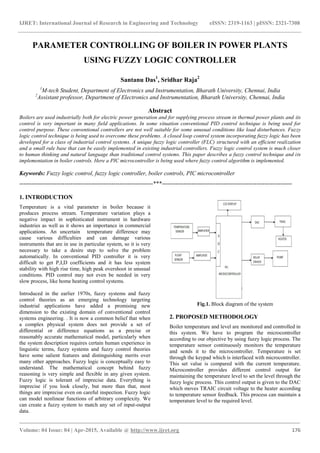
- 1. IJRET: International Journal of Research in Engineering and Technology eISSN: 2319-1163 | pISSN: 2321-7308 _______________________________________________________________________________________ Volume: 04 Issue: 04 | Apr-2015, Available @ http://www.ijret.org 176 PARAMETER CONTROLLING OF BOILER IN POWER PLANTS USING FUZZY LOGIC CONTROLLER Santanu Das1 , Sridhar Raja2 1 M-tech Student, Department of Electronics and Instrumentation, Bharath University, Chennai, India 2 Assistant professor, Department of Electronics and Instrumentation, Bharath University, Chennai, India Abstract Boilers are used industrially both for electric power generation and for supplying process stream in thermal power plants and its control is very important in many field applications. In some situation conventional PID control technique is being used for control purpose. These conventional controllers are not well suitable for some unusual conditions like load disturbances. Fuzzy logic control technique is being used to overcome these problems. A closed loop control system incorporating fuzzy logic has been developed for a class of industrial control systems. A unique fuzzy logic controller (FLC) structured with an efficient realization and a small rule base that can be easily implemented in existing industrial controllers. Fuzzy logic control system is much closer to human thinking and natural language than traditional control systems. This paper describes a fuzzy control technique and its implementation in boiler controls. Here a PIC microcontroller is being used where fuzzy control algorithm is implemented. Keywords: Fuzzy logic control, fuzzy logic controller, boiler controls, PIC microcontroller --------------------------------------------------------------------***------------------------------------------------------------------ 1. INTRODUCTION Temperature is a vital parameter in boiler because it produces process stream. Temperature variation plays a negative impact in sophisticated instrument in hardware industries as well as it shows an importance in commercial applications. An uncertain temperature difference may cause various difficulties and can damage various instruments that are in use in particular system, so it is very necessary to take a desire step to solve the problem automatically. In conventional PID controller it is very difficult to get P,I,D coefficients and it has less system stability with high rise time, high peak overshoot in unusual conditions. PID control may not even be needed in very slow process, like home heating control systems. Introduced in the earlier 1970s, fuzzy systems and fuzzy control theories as an emerging technology targeting industrial applications have added a promising new dimension to the existing domain of conventional control systems engineering. . It is now a common belief that when a complex physical system does not provide a set of differential or difference equations as a precise or reasonably accurate mathematical model, particularly when the system description requires certain human experience in linguistic terms, fuzzy systems and fuzzy control theories have some salient features and distinguishing merits over many other approaches. Fuzzy logic is conceptually easy to understand. The mathematical concept behind fuzzy reasoning is very simple and flexible in any given system. Fuzzy logic is tolerant of imprecise data. Everything is imprecise if you look closely, but more than that, most things are imprecise even on careful inspection. Fuzzy logic can model nonlinear functions of arbitrary complexity. We can create a fuzzy system to match any set of input-output data. Fig.1. Block diagram of the system 2. PROPOSED METHODOLOGY Boiler temperature and level are monitored and controlled in this system. We have to program the microcontroller according to our objective by using fuzzy logic process. The temperature sensor continuously monitors the temperature and sends it to the microcontroller. Temperature is set through the keypad which is interfaced with microcontroller. This set value is compared with the current temperature. Microcontroller provides different control output for maintaining the temperature level to set the level through the fuzzy logic process. This control output is given to the DAC which moves TRAIC circuit voltage to the heater according to temperature sensor feedback. This process can maintain a temperature level to the required level.
- 2. IJRET: International Journal of Research in Engineering and Technology eISSN: 2319-1163 | pISSN: 2321-7308 _______________________________________________________________________________________ Volume: 04 Issue: 04 | Apr-2015, Available @ http://www.ijret.org 177 Float sensor monitors the water level in tank and sends it to the microcontroller. If the water level increases the desired level then relay will turn OFF the motor and if water level decreases below the desired level then relay will automatically turn ON the motor. 2.1 Temperature Control Thermistor is used to measure the temperature. A thermistor is a type of resistor whose resistance varies significantly with temperature, more than the other standard resistors. Thermistors are widely used as an inrush current limiter, temperature sensors (NTC type typically), self-resetting overcurrent protectors, and self-regulating heating elements. Fig.2. Thermistor In this case the temperature is being measured using 47k thermistor, which gives an analog output voltage. The output voltage of this thermistor is given to the analog input port of microcontroller. A analog to digital converter(ADC) is in- built on PICF877A microcontroller. ADC converts the analog voltage to corresponding digital word. The physical parameter is displayed on the LCD which is being interfaced with the microcontroller. Fig.3. Block diagram of fuzzy temperature control system Fuzzy control algorithm is conditional statement between input variable boiler temperature and output variable heater voltage. Fuzzy inference is the process of formulating the mapping from a given input to an output using fuzzy logic. The mapping then provides a base from which decisions can be made, or patterns discerned. The process of fuzzy inference involves with the factors like membership functions, fuzzy logic operators and if-then rules. Fuzzy inference system gives defuzzified output according to rule base and data base and microcontroller gives control action according to the defuzzified values. Fig.4. Interfacing of LCD and DAC with microcontroller
- 3. IJRET: International Journal of Research in Engineering and Technology eISSN: 2319-1163 | pISSN: 2321-7308 _______________________________________________________________________________________ Volume: 04 Issue: 04 | Apr-2015, Available @ http://www.ijret.org 178 Microcontroller interfacing with LCD and DAC is shown in the figure above. The thermistor circuit is connected to RA0 port of microcontroller. DAC output is given to the TRIAC. TRIAC circuit is shown below. Fig.5. Circuit diagram of TRIAC 2.1.1 TRIAC TRIAC(Triode for Alternating Current) is an electronic component approximately equivalent to two silicon- controlled rectifiers(SCR) joined in inverse parallel (paralleled but with the polarity reversed) and with their gates connected together so this results in a bidirectional electronic switch which can conduct current in either direction when it is triggered (turned on). It can be triggered by either a positive or a negative voltage being applied to its gate electrode. Once triggered, the device continues to conduct until the current through it drops below a certain threshold value, such as at the end of a half-cycle of alternating current (AC) mains power. This makes the TRIAC a very convenient switch for AC circuits, allowing the control of very large power flows with milliampere scale control currents. This circuit is designed to control the 230V AC load such as heater, motor etc. The 230V AC voltage is stepped down with the help of step down transformer. The stepped down voltage is rectified by the full wave rectifier. After the rectification the pulsating rectified voltage is given to base of the transistor Q1. Whenever peak pulse comes to the transistor Q1 starts conducting and ground voltage is given to the Q2 transistor base. Rest of the time 12V is given to the base of the Q2 transistor which is connected across the feedback capacitor of U1A saw tooth generator. The saw tooth generator is constructed by LM1458 operational amplifier. The LM1458 is the general purpose duel operational amplifier with sharing common supply. U1A deliver the saw tooth wave output which is given to the non-inverting input terminal of comparator. The comparator is constructed by the U1B. The 12V square wave signal is given to the inverting input terminal. The 12V square wave signal is generated by the comparator U5 which is constructed by LM 741 operational amplifier. The U1B comparator compares the input saw tooth wave and square wave signal and outputs the +12V to -12V square pulse. The -12V square pulse is rectified by D3 diode. The positive 12V square pulse is given to the isolation circuit. The isolation is constructed by the MOC3011 Optocoupler. The isolation is used to separate the 230V AC voltage and DC voltages. The optocoupler consists of photo LED and photo transistor. Whenever the 12V signal is given to photo LED the light rays’ falls on the photo transistor. Now the photo transistor is conducting and high pulse is given to TRIAC gate. So the TRIAC is conducting and
- 4. IJRET: International Journal of Research in Engineering and Technology eISSN: 2319-1163 | pISSN: 2321-7308 _______________________________________________________________________________________ Volume: 04 Issue: 04 | Apr-2015, Available @ http://www.ijret.org 179 230V AC voltage is given to load. Depending on the pulse given to TRIAC gate the conduction angel is varied. Due to that variable AC voltage is given to load in order to control the load to desired level. 2.2 Level Control Level is also an important parameter in boiler. Boiler produces process stream so it is necessary to control the water level with process stream demand. In this system a float sensor is used to monitor the level. Float sensor monitors the water level in tank and sends it to the microcontroller. If water level increases the desired level then relay will turn OFF the motor and if water level decreases the desired level then relay will turn ON the motor automatically. 2.3 Software Implementation The input variable for fuzzy temperature control system is error (difference between set temperature and measured temperature from sensor). Triangular membership functions are used for input variable. The following membership functions are used. Input Variable Z Zero L Low M Medium H High VH Very High Microcontroller gives the controlled signal to the DAC (Digital to analog converter). DAC gives an analog output which is given to the TRIAC circuit. TRIAC controls the voltage passing through the heater. So output variable in this system is heater. Output Variable VL Very low L Low M Medium H High VH Very High Fig.6. Membership functions for input variable Fig.7. membership functions for output variable Fig.8. Fuzzy rules for input and output relationship 2.4 Programming in Embedded C MPLAB IDE is a software program that runs on a PC to develop applications for Microchip microcontrollers. It is called an Integrated Development Environment, or IDE, because it provides a single integrated “environment” to develop code for embedded microcontrollers. The programming with MPLAB is shown in figure.
- 5. IJRET: International Journal of Research in Engineering and Technology eISSN: 2319-1163 | pISSN: 2321-7308 _______________________________________________________________________________________ Volume: 04 Issue: 04 | Apr-2015, Available @ http://www.ijret.org 180 Fig.9. Embedded C program 3. RESULT AND DISCUSSION The fuzzy temperature control and level control portions are verified in a prototype model. Due to some component limitations the entire system response is not verified in software. 3.1 Results for Temperature Control Fig.10. LCD is displaying measured temperature =32 °C and set temperature =102 °C Fig.11. LCD is displaying measured temperature=32°C, set temperature =102 °C and output voltage to heater is 146 V
- 6. IJRET: International Journal of Research in Engineering and Technology eISSN: 2319-1163 | pISSN: 2321-7308 _______________________________________________________________________________________ Volume: 04 Issue: 04 | Apr-2015, Available @ http://www.ijret.org 181 Fig.12. LCD is displaying measured Temperature = 32 °C, set temperature =102 °C and output voltage to heater is 145 V Fig.13. LCD is displaying measured temperature 32 °C and set temperature 21 °C In this case set temperature is less than measured temperature so TRIAC will turn OFF the heater and for that reason voltage to heater is 0V. 3.2 Results for Level Control Fig.14. LCD is displaying measured value = 003 and set value =154 In case of water level control ADC values are shown in LCD. We have to calibrate it in terms of level. Here the LCD is indicating that measured value which is less than set value so the relay is turned ON and it will drive the water pump. Fig.15. LCD is displaying measured value=207 and set value =65 Here LCD is indicating that measured value is less than set value so the relay is turned OFF. Red LED is indicating that relay is turned OFF. 4. CONCLUSION Fuzzy based boiler parameter control system is found to perform as expected. The change of temperature and level is correspondingly detected by thermistor and float sensor. Data is displayed on LCD continuously. The change of temperature corresponding to the sensor’s output it is evaluated by the use of fuzzy logic. According to the fuzzy rule base table, the analog data is fuzzified. After
- 7. IJRET: International Journal of Research in Engineering and Technology eISSN: 2319-1163 | pISSN: 2321-7308 _______________________________________________________________________________________ Volume: 04 Issue: 04 | Apr-2015, Available @ http://www.ijret.org 182 Defuzzification, which is processed by the microcontroller (PIC16F877A) send it to A/D converter, for digital output. The entire system is automated and requires no manual operation. FUTURE SCOPE Thermistor can measure temperature range, typically -40 °C to 120°C. The temperature below 0° C can’t be shown in this system but LCD can show negative temperature. Only two position control system is being implemented in water level system. We can implement more precise fuzzy logic control to the water level system. REFERENCES [1] “Design with PIC Microcontroller” by John B. Peatman. [2] Ying, H. B.G. Hu, "Introduction to Fuzzy Control," International Journal of Fuzzy Systems, Vol 5, (2003) [3] “Fuzzy systems for control applications” by Emil M. Petriu, Dr. Eng., P. Eng., FIEEE, Professor School of Information Technology and Engineering, University of Ottawa [4] “Tutorial on Fuzzy Logic Applications in Power Systems” prepared for the IEEE-PES winter meeting in Singapore January, 2000 by K. Tomsovic, Washington State University M.Y. Chow, North Carolina State University [5] P. Singhala, D. N. Shah, B. Patel, “Temperature Control using Fuzzy Logic”, International Journal of Instrumentation and Control systems(IJICS), vol. 4, no.1, January 2014 [6] R.M. Aguilar, V. Muñoz and Y. Callero, “Design of a Fuzzy Temperature Controller” University of La Laguna, Spain [7] “Fuzzy logic basic and neural network basic concept and application” by Channakesa r. Alavas, new age international publication [8] Tanaka K, Sugeno M, “Stability Analysis and Design of Fuzzy Control Systems, Fuzzy Sets and Systems”, Vol.45, No.2, (January 2002), pp. 135-156, ISSN 0165-0114, North-Holland [9] “Implementation of fuzzy temperature control using microprocessor”, M D Hanamane, R R Mudholkar, B T Jadhav and S R Sawant, Department of Electronics, Shivaji University, Kolhapur 416 004 [10] “Comparative Analysis of Room Temperature Controller Using Fuzzy Logic & PID ” Jay Kumar, Richa Kapoor, Brijebdra, Hemant, Jyoti, Electronics & Communication, RBS Engineering Technical Campus Agra, India [11] “ Process Control” by K. Krishnaswamy [12] “Temperature control based on traditional PID versus fuzzy controllers” by Peter Galan, Control Software Designer, Nortel Networks [13] Om Prakash Verma, Himanshu Gupta,“Fuzzy Logic Based Water Bath Temperature Control System”, International Journal of Advanced Research in Computer Science and Software Engineering(IJARCSSE), Volume 2, Issue 4, April 2012 [14] https://www.pcsilencioso.com/cpemma/rs_thermistor s.pdf [15] www.murata.com/~/media/webrenewal/support/.../th ermistor/.../r44e.ash