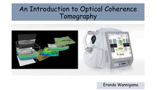
Introduction to Optical Coherence Tomography (OCT) Imaging
•Als PPTX, PDF herunterladen•
6 gefällt mir•1,581 views

Ophthalmoogy

Empfohlen
Weitere ähnliche Inhalte
Was ist angesagt?
Was ist angesagt? (20)
Ähnlich wie Introduction to Optical Coherence Tomography (OCT) Imaging
Ähnlich wie Introduction to Optical Coherence Tomography (OCT) Imaging (20)
Kürzlich hochgeladen
Kürzlich hochgeladen (20)
Introduction to Optical Coherence Tomography (OCT) Imaging
- 1. An Introduction to Optical Coherence Tomography Eranda Wannigama
- 2. Overview • History and evolution. • What is OCT ? • OCT Physics • What is OCT Angiography • Interpretation of OCT. • Limitations.
- 3. History • OCT was first introduced in 1991 and has found many uses outside of ophthalmology, where it has been used to image certain non-transparent tissues. • Due to the transparency of the eye (i.e. the retina can be viewed through the pupil), OCT has gained wide popularity as an ophthalmic diagnostic tool. Optical coherence tomogram of a fingertip. It is possible to observe the sweat glands, having "corkscrew appearance"
- 5. What is OCT ? • Optical Coherence Tomography (OCT) is a non-invasive, noncontact, technique for obtaining sub-surface images of translucent or opaque materials at a resolution equivalent to a low- power microscope. • Reflected light is used instead of sound waves(It is an ‘optical ultrasound’, imaging reflections from within tissue to provide cross-sectional images) • it provides tissue morphology imagery at much higher resolution (better than 10 µm) than other imaging modalities such as MRI or ultrasound.
- 6. Comparison of various imaging methods according to their resolutions and penetration depths. The length of the “pendulum” represents the penetration depth while the diameter of the circle represents the spatial resolution of the imaging
- 7. • Piezoelectric effect( curie brothers 1880) • Came in to ophthalmology in 1956 • Resolution 50 micro m • High frequency 35-50 MHz • Can combine with Doppler / movement and flow within a tissue / colour coded for high and low flow • Penetrates hazy media B -SCAN
- 8. • Contact • Poor resolution • Can image when media hazy • Less costly B-SCAN VS OCT
- 9. The key benefits of OCT over B scan: Advantages • Non-contact • Minimal cooperation needed • Resolution ~ 10 μm • Pick up earliest signs of disease • Quantitatively monitor disease/staging Disadvantages • Best for optically transparent tissues • Diminished penetration through Retinal/subretinal hemorrhage • Requires pupil diameter > 4 mm
- 10. • Fiber-based OCT system in a Michelson configuration. The light (Infrared light 840nm)from a low-coherence source is split in two by the coupler with each part traveling along a separate arm of the interferometer, • the reference and the sample arm. The light backscattered from the reference mirror and from the sample recombine at the coupler and generate an interference pattern, which is recorded by a single point detector OCT Basic principle
- 11. • Interferometry is used to record the optical path length of received photons allowing rejection of most photons that scatter multiple times before detection. • Thus OCT can build up clear 3D images of thick samples by rejecting background signal while collecting light directly reflected from surfaces of interest.
- 12. Axial resolution, or definition, determines which retinal layers can be distinguished. Axial resolution is determined by the light source. Transverse resolution is determined by optics of the eye, as limited by pupil size, and as corrected by the scanner
- 13. OCT Platforms • Time domain (TD-OCT) • Fourier-domain OCT (FD-OCT). Fourier-domain OCT imaging can also be done in two ways: spectral-domain OCT (SD-OCT) swept-source OCT (SS-OCT). • High definition- HD • Array of detectors/ 100000 scans per second ( 200 times faster than time domain)
- 14. 1. Time Domain OCT • In TD-OCT a mirror in the reference arm of the inter-ferometer is moved to match the delay in various layers of the sample • The resulting interference is processed to produce the axial scan waveform. • The reference mirror must move one cycle for each axial scan. The need for mechanical movement limits the speed of image acquisition.
- 15. Fourier-domain OCT (FD-OCT) • In FD-OCT the reference mirror is kept stationary. The spectral pattern of the interference between the sample and the reference reflections is measured • The spectral interferogram is fourier transformed to provide an axial scan. • The absence of moving part allows the image to be acquired very rapidly . • the full spectral bandwidth sets the axial resolution. • Reflections from all layers in the sample are detected simultaneously. • This parallel axial scan is much more efficient, resulting in both greater speed and higher signal- to-noise ratio.
- 16. TD-OCT vs FD-OCT • Spectral domain measures retinal thickness from RPE to ILM • Time domain measures retinal thickness from IS/OS to ILM
- 17. Swept-source OCT (SS-OCT) • SS-OCT has improved acquisition speed, volume and depth of ocular tissue measurements compared with SD-OCT technology. • has a scan speed of 100,000 A-scans per second and uses a 1050nm wavelength to pass through cataracts and retinal hemorrhages. • It is the first ophthalmic diagnostic technology to demonstrate the entire structure of the posterior precortical vitreous pocket (PPVP) in vivo. .
- 18. Swept-source OCT (SS-OCT) • The roles of the PPVP in physiological posterior vitreous detachment and Vitreoretinal interface disorders have now been elucidated • Deeper penetration of SS-OCT has made it possible to view the choroid. • It also has an important role in central serous chorioretinopathy and uveitis. • Treat Harada disease by monitoring the choroidal thickness.
- 19. OCT Angiography • Optical coherence tomography angiography (OCT-A) emerged as a non-invasive technique for imaging the microvasculature of the retina and choroid, and the first clinical studies using this innovative technology were published in 2014. OCT-A technology uses laser light reflectance of the surface of moving red blood cells to accurately depict vessels through different segmented areas of the eye, thus eliminating the need for intravascular dyes
- 20. OCT interpretation 2 MODES OF INTERPRETATION - Objective & Subjective For accurate interpretation both have to be combined OCT reading must be done in 2 stages : 1.Qualitative and quantitative analysis 2.Deduction and synthesis
- 21. Qualitative Analysis • Morphological studies - - Overall retinal structural changes, changes in retinal outline , retinal structural changes and morphological changes in the post layers -Anomalous structures- pre/epi/intra/sub retinal • Reflectivity study - hyper/hypo/ shadow areas Quantitative Analysis • Thickness, Volumetery and shadow areas
- 22. Color coding in OCT Those with low reflectivity are represented by dark colors (black and blue). photoreceptor layer,choroid,vitreous fluid or blood Intermediate reflectivity is shown Green. Highly reflective structures are shown in bright colures (white and red) Nerve Fiber Layer, RPE,choriocapillaris
- 23. Interpretation of retinal scan • Vitreous anterior to retina is non reflective and is seen as a dark space. • Vitreo retinal interface is well defined due to contrast between the non reflective vitreous and backscattering retina
- 24. 1. Anterior boundary of retina formed by highly reflective RNFL is seen as a red layer due to bright back scattering. 2. Posterior boundary of retina is also seen as a red layer representing highly reflective (RPE) and chorio capillaries 3.Outer segment of retinal photoreceptors, being minimally reflective are represented by dark layer just anterior to RPE 4.Different intermediate layers of neurosensory retina seen as an alternating layer of moderate and low reflectivity. Retinal layers are represented as below
- 25. xxx
- 26. xxx xxxx
- 27. xxx Macular Change Analysis ETDRS grid with thickness values is overlaid on retinal thickness maps.
- 28. Macular Thickness Normative data Macular thickness is compared to an age-matched normative database as indicated by a stop-light color code
- 29. Automatic fovea finder Macula Thickness Analysis is aligned with fovea location (left)
- 30. xxx
- 31. xxx
- 32. Advanced Vaisualization The Tissue Layer image allows you to isolate and visualize a layer of the retina. The thickness and placement of the layer are adjustable. This provides an optical biopsy of the retina by extracting the layer of interest
- 33. Each high definition line is comprised of 4096 A-scans Rotation, length of lines and height of scan area can be adjusted Custom 5-Line Raster Scan
- 34. Limitations • OCT utilizes light waves (unlike ultrasound which uses sound waves) media opacities can interfere with optimal imaging. eg; vitreous hemorrhage, dense cataract or corneal opacities. • Patient movement can diminish the quality of the image. • The quality of the image is also dependent on the operator.