Vortex vn2000 datasheet badger meter flow meters hot tap insertion meter
•
0 gefällt mir•70 views

Vortex vn2000 datasheet badger meter flow meters hot tap insertion meter. ĐT: 028 77727979 - sales@envimart.vn - www.envimart.vn

Empfohlen
Empfohlen
Weitere ähnliche Inhalte
Was ist angesagt?
Was ist angesagt? (20)
Ähnlich wie Vortex vn2000 datasheet badger meter flow meters hot tap insertion meter
Ähnlich wie Vortex vn2000 datasheet badger meter flow meters hot tap insertion meter (20)
Mehr von ENVIMART
Mehr von ENVIMART (20)
Kürzlich hochgeladen
Kürzlich hochgeladen (20)
Vortex vn2000 datasheet badger meter flow meters hot tap insertion meter
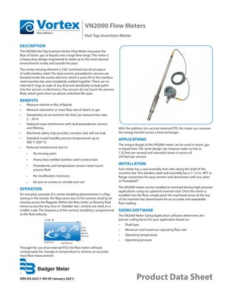
- 1. VN2000 Flow Meters Hot Tap Insertion Meter VRX-DS-02211-EN-09 (January 2021) Product Data Sheet DESCRIPTION The VN2000 Hot Tap Insertion Vortex Flow Meter measures the flow of steam, gas or liquids over a large flow range. The meter is a heavy duty design engineered to stand up to the most abusive environments inside and outside the pipe. The vortex sensing element is CNC machined out of one piece of solid stainless steel. The dual ceramic piezoelectric sensors are bonded inside the vortex element, which is press-fit to the stainless steel insertion bar and completely welded together. There are no internal O-rings or seals of any kind and absolutely no leak paths into the sensors or electronics. Our sensors do not touch the process fluid, which gives them an almost unlimited life span. BENEFITS • Measure volume or Btu of liquids • Measure volumetric or mass flow rate of steam or gas • Standardize on an insertion bar that can measure line sizes 2…36 in. • Reduced noise interference with dual piezoelectric sensors and filtering • Machined safety stop provides constant seal, will not leak • Standard model handles process temperatures up to 400° F (204° C) • Reduced maintenance due to: • No moving parts • Heavy duty welded stainless steel construction • Piezoelectric and temperature sensors never touch process fluid • No recalibration necessary • No pins or screws to corrode and rust OPERATION An everyday example of a vortex shedding phenomenon is a flag waving in the breeze: the flag waves due to the vortices shed by air moving across the flagpole. Within the flow meter, as flowing fluid moves across the tiny strut or“shedder bar”, vortices are shed on a smaller scale. The frequency of the vortices shedding is proportional to the fluid velocity. FLOW Small Strut Shed Vortices Dual Piezo- electric Sensors Through the use of an internal RTD, the flow meter software compensates for changes in temperature to achieve an accurate mass flow measurement. With the addition of a second external RTD, the meter can measure the energy transfer across a heat exchanger. APPLICATIONS The unique design of the VN2000 meter can be used in steam, gas or liquid lines. The same design can measure water as low as 1.32 feet per second and saturated steam in excess of 250 feet per second. INSTALLATION Each meter has a seal assembly that rides along the shaft of the insertion bar. This stainless steel seal assembly has a 1-1/2 in. NPT or flange connection for easy connect and disconnect with any valve or Threadolet®. The VN2000 meter can be installed or removed during high pressure applications using our optional insertion tool. Once the meter is installed into the flow, simply point the machined arrow at the top of the insertion bar downstream for an accurate and repeatable flow reading. SIZING SOFTWARE The VN2000 Meter Sizing Application software determines the precise scaling factor for your application based on: • Fluid type • Minimum and maximum operating flow rate • Operating temperature • Operating pressure
- 2. Specifications Page 2 January 2021 VRX-DS-02211-EN-09 SPECIFICATIONS Uncertainty Volumetric Flow Repeatability Liquids ±1.0% of reading ±0.25% of reading Steam ±1.0% of reading ±0.25% of reading Gas ±1.0% of reading ±0.25% of reading Mass or Heat Flow Repeatability Liquids ±1.0% of reading ±0.25% of reading Steam ±1.0% of reading ±0.25% of reading Gas ±1.0% of reading ±0.25% of reading Velocity – Liquid 1.32…32 ft/s (0.402…9 m/s) Velocity – Gas cube root (140/ρ) ft/s… 300 ft/sec (91 m/sec) Reynolds Range 10,000…7,000,000 depending on fluid density Straight Run Pipe Upstream 10 diameters; downstream 5 diameters with one 90° elbow before the meter Pipe sizes 2…36 in. (50…900 mm) Fluid temperature –250…400° F (–120…204°C) Maximum Pressure 1000 psi (68.9 bar) Wetted Materials Stainless steel 304L Hot Tap Connections 1-1/2 in: NPT, ASME/ANSI 150, 300 flanges; Sealing assembly: Two ethylene propylene O-rings; Optional removable extractor Measurement Options Sensors Volumetric flow rate Dual piezo vortex sensors Mass flow rate based on velocity and temperature Dual piezo vortex sensors RTD embedded in sensor: 100 Ohm, 3 wire BTU/Energy Dual piezo vortex sensors RTD embedded in sensor: 100 Ohm, 3 wire External 100 Ohm RTD input Units of measure Units Base Steam Liquids Gases Energy Meter English Pounds (LB) Tons (TON) Cubic Feet (FT3) Gallons (GAL) Pounds (LB) Tons (TON) Cubic Feet (FT3) Gallons (GAL) Oil Barrels (BBL) Pounds (LB) Tons (TON) Cubic Feet (FT3) U.S. Gallons (GAL) British Thermal Units (BTU) Tons (TON) Metric Kilograms (KG) Tonnes (TNN) Cubic Meters (M3) Liters (LTR) Kilograms (KG) Tonnes (TNN) Cubic Meters (M3) Liters (LTR) Kilograms (KG) Metric Tonnes (TNN) Natural Cubic Meters (Nm3) Natural Liters (Nlt) — Actual English — — Pounds (LB) Tons (TON) Actual Cubic Feet (Acf) U.S. Gallons (GAL) — Natural Metric — — Kilograms (KG) Metric Tonnes (TNN) Actual Cubic Meters (Am3) Actual Liters (Alt) — Units of measure are used for flow rate, mass flow rate, heat/energy flow rate; volume total, mass total, heat/energy total Measurement interval Second, minute, hour, day Transmitter Display 2×16 characters reflective display Rotatable display Flow rate: 6 digits with decimal Totalizer Keypad 4 membrane buttons Power 14…36 V DC; loop powered with 4…20 mA option, 28V DC max Operating Temperature 32…140° F (0… 60° C) 5…95% relative humidity non-condensing Output One 4…20 mA, 10…36V max load, 24-bit resolution; Available Communication and I/O Standard option "S" Digital Output One min. input resistance 1000 Ohm Max output frequency = 12.5 Hz Opto isolator 5…24V DC Available Communication and I/O Standard option "S" Communication EIA-485 with Modbus RTU (9600, 14400, 19200 baud) available Communication and I/O Standard option "M" or BACnet MS/ TP (9600, 19200, 38400, 76800 baud) available Communication and I/O Standard option "B" Enclosure General purpose Mounting Integral meter or remote pipe and wall; Up to 30 ft (10 m) from pipe Cable Cable jacket material: polyurethane (gray) Operating temperature –13…185° F (–25…85 ° C)
- 3. Flow Rate Tables Page 3 January 2021 VRX-DS-02211-EN-09 FLOW RATE TABLES Saturated Steam Minimum…Maximum Flow Rates in lb/hr Pipe Line Size in. Pressure (psig); Density (lb/ft3 ) 5 psig 0.0486 lb/ft3 50 psig 0.1503 lb/ft3 100 psig 0.2577 lb/ft3 150 psig 0.3614 lb/ft3 200 psig 0.4688 lb/ft3 300 psig 0.6481 lb/ft3 400 psig 0.8613 lb/ft3 2 58.38…1019 124.0…3152 177.7…5404 222.7…7580 264.9…9832 328.7…13592 397.4…18064 3 128.6…2244 273.2…6945 391…11905 490.5…16698 583.5…21662 724.2…29944 875.5…39797 4 221.5…3865 470.5…11959 674.0…20501 844.7…28755 1005…37302 1247…51565 1508…68531 5 348.1…6074 739.4…18794 1057…32218 1327…45188 1579…58620 1960…81035 2369…107697 6 502.6…8771 1068…27140 1530…46525 1917…65256 2280…84653 2830…117021 3421…155525 8 870.4…15188 1849…46997 2649…80564 3319…112999 3949…146586 4900…202637 5924…269310 10 1372…23939 2914…74078 4175…126988 5232…178113 6224…231055 7724…319403 9338…424496 12 1947…33981 4137…105152 5927…180256 7427…252827 8835…327976 10964…453385 13255…602561 14 2354…41075 5000…127102 7164…217884 8977…305604 10679…396440 13253…548028 16022…728344 16 3075…53649 6531…166010 9357…284583 11725…399157 13948…517799 17310…715791 20927…951306 18 3892…67907 8267…210132 11843…360218 14842…505242 17655…655418 21911…906031 26489…1204139 20 4836…84381 10273…261109 14717…447606 18442…627814 21938…814421 27227…1125833 32915…1496262 22 6170…107670 13108…333173 18778…571142 23532…801085 27993…1039195 34741…1436554 41999…1909218 24 6994…122044 14858…377651 21285…647389 26674…908029 31730…1177925 39379…1628331 47606…2164096 26 8712…152020 18507…470408 26513…806397 33225…1131054 39523…1467242 49051…2028274 59299…2695631 28 10147…177056 21555…547880 30880…939203 38697…1317327 46032…1708882 57129…2362310 69064…3139574 30 11691…203999 24835…631254 35579…1082126 44586…1517793 53037…1968932 65823…2721797 79574…3617341 32 12815…223615 27223…691952 39000…1186179 48873…1663737 58137…2158256 72152…2983512 87226…3965167 36 16264…286802 34550…878194 49497…1505443 62027…2111538 73785…2739159 91572…3786537 110703…5032408 Saturated Steam Minimum…Maximum Flow Rates in kg/hr Pipe Line Size mm Pressure (bar); Density (kg/m3 ) 0.4 bar 0.7779 kg/m3 3.4 bar 2.372 kg/m3 6.9 bar 4.127 kg/m3 11 bar 6.125 kg/m3 13.8 bar 7.508 kg/m3 20.7 bar 10.38 kg/m3 27 bar 13.79 kg/m3 50 26.48…462.0 55.70…1409 80.58…2451 104.9…3637 120.1…4459 149.1…6164 180.2…8192 75 58.33…1018 122.7…3104 177.5…5399 231.0…8013 264.8…9824 328.4…13580 397.0…18048 100 100.4…1753 211.3…5345 305.7…9297 397.8…13799 455.7…16917 565.5…23385 683.7…31080 125 157.9…2754 332.1…8400 480.4…14611 625.1…21685 716.1…26585 888.8…36750 1074…48842 150 228.0…3978 479.5…12130 693.7…21100 902.7…31315 1034…38391 1283…53071 1552…70533 200 394.7…6888 830.4…21004 1201…36537 1563…54226 1791…66479 2222…91899 2687…122136 250 622.2…10857 1309…33108 1894…57591 2464…85472 2823…104787 3503…144854 4235…192515 300 883.2…15411 1858…46996 2688…81749 3498…121326 4007…148742 4973…205617 6011…273270 350 1068…18628 2246…56806 3249…98813 4228…146652 4843…179791 6011…248539 7266…330315 400 1394…24330 2933…74195 4243…129063 5522…191546 6326…234830 7851…324622 9491…431431 450 1765…30797 3713…93914 5371…163364 6989…242454 8007…297242 9937…410898 12013…546095 500 2193…38268 4614…116698 6674…202996 8685…301273 9949…369352 12348…510582 14927…678577 550 2798…48830 5887…148906 8516…259021 11082…384421 12695…471290 15756…651498 19047…865859 600 3172…55349 6673…168784 9653…293600 12561…435741 14390…534207 17859…738472 21590…981449 650 3951…68943 8312…210240 12024…365713 15647…542766 17924…665416 22245…919852 26893…1222508 700 4602…80297 9681…244865 14004…425942 18224…632154 20876…775003 25909…1071343 31322…1423943 750 5302…92517 11154…282127 16135…490760 20997…728352 24053…892940 29852…1234375 36088…1640517 800 5812…101413 12226…309255 17687…537949 23016…798387 26366…978801 32722…1353067 39558…1798262 900 7376…128708 15517…392493 22448…682741 29211…1013276 33462…1242249 41529…1717250 50205…2282271
- 4. Flow Rate Tables Page 4 January 2021 VRX-DS-02211-EN-09 Liquid Minimum…Maximum Flow Rates in US Gal/min* Pipe Line Size in. Density 62.3 lb/ft3 2 13.80…313.7 gpm 3 30.41…691.2 gpm 4 52.37…1190 gpm 5 82.3…1871 gpm 6 118.9…2701 gpm 8 205.8…4678 gpm 10 324.4…7373 gpm 12 460.5…10466 gpm 14 556.6…12650 gpm 16 727.0…16523 gpm 18 920.2…20914 gpm 20 1143…25988 gpm 22 1459…33160 gpm 24 1654…37587 gpm 26 2060…46819 gpm 28 2399…54530 gpm 30 2764…62828 gpm 32 3030…68869 gpm 34 3439…78158 gpm 36 3846…87406 gpm * Standard conditions of 70° F (21.11° C) Liquid Minimum…Maximum Flow Rates in Liter/min * Pipe Line Size in. Density 997.77 kg/m3 50 52.26…1188 lpm 80 115.1…2616 lpm 100 198.2…4506 lpm 125 311.5…7018 lpm 150 449.9…10225 lpm 200 779.1…17706 lpm 250 1228…27909 lpm 300 1743…39616 lpm 350 2107…47885 lpm 400 2752…62544 lpm 450 3483…79167 lpm 500 4328…98373 lpm 550 5523…125523 lpm 600 6260…142280 lpm 650 7798…177226 lpm 700 9082…206413 lpm 750 10464…237825 lpm 800 11470…260693 lpm 850 13018…295855 lpm 900 14558…330859 lpm * Standard conditions of 70° F (21.11° C)
- 5. Flow Rate Tables Page 5 January 2021 VRX-DS-02211-EN-09 Air Minimum…Maximum Flow Rates in ft3 /min (SCFM 1 ) Pipe Line Size in. Pressure (psig); Density (lb/ft3 ) 0 psig 0.075 lb/ft3 50 psig 0.3312 lb/ft3 100 psig 0.5871 lb/ft3 150 psig 0.843 lb/ft3 200 psig 1.0998 lb/ft3 300 psig 1.611 lb/ft3 400 psig 2.123 lb/ft3 500 psig 2.635 lb/ft3 1000 psig 5.194 lb/ft3 2 17.05…344.2 45.82…1515 67.13…2686 85.45…3857 102.0…5028 131.6…7370 158.2…9711 182.7…12053 287.4…237062 3 37.57…758.4 100.9…3338 147.9…5918 188.3…8497 224.7…11077 290.0…16236 348.5…21395 402.6…26554 633.1…52350 4 64.69…1306 173.8…5748 254.7…10190 324.2…14632 386.9…19074 499.3…27959 600.2…36843 693.2…45727 1090…90148 5 101.7…2052 273.2…9033 400.2…16014 509.5…22995 608.0…29976 7841.7…43937 943.2…57899 1089…71861 1713…141669 6 146.8…2964 394.5…13045 578.0…23126 735.7…33207 878.0…43288 1133…63450 1362…83612 1573…103774 2474…204583 8 254.2…5132 683.1…22589 1001…40045 1274…57501 1520…74958 1962…109871 2359…144784 2724…179696 4284…354261 10 400.7…8090 1077…35605 1578…63120 2008…90636 2397…118151 3093…173182 3718…228213 4294…283244 6753…558398 12 568.8…11483 1528…50540 2239…89598 2850…128655 3402…167713 4390…245828 5277…323942 6095…402057 9585…792632 14 687.6…13880 1848…61090 2707…108301 3446…155512 4112…202722 5307…297143 6379…391565 7368…485986 11586…958092 16 898.1…18129 2413…79792 3535…141454 4500…203117 5371…264780 6931…388106 8332…511431 9623…634757 15133…1251385 18 1137…22947 3054…100998 4475…179050 5696…257101 6798…335152 8773…491254 10546…647357 12181…803459 19155…1583972 20 1413…28514 3795…125500 5561…222487 7078…319473 8447…416459 10902…610432 13104…804405 15135…998378 23802…1968241 22 1802…36384 4843…160137 7095…283891 9032…407645 10779…531399 13910…778907 16721…1026414 19313…1273922 30371…2511460 24 2043…41241 5489…181516 8042…321790 10237…462065 12218…602340 15767…882889 18953…1163439 21891…1443988 34426…2846736 26 2545…51370 6838…226099 10018…400827 12752…575555 15219…750284 19640…1099741 23609…1449197 27268…1798654 42882…3545938 28 2964…59830 7964…263335 11668…466839 14852…670343 17725…873848 22874…1282857 27497…1687865 31758…2094874 49944…4129918 30 3415…68935 9176…303408 13443…537881 17112…772353 20422…1006826 26355…1475772 31681…1944717 36591…2413663 57544…4758391 32 3743…75563 10058…332582 14736…589601 18758…846619 22386…1103638 28890…1617675 34727…2131712 40110…2645750 63077…5215936 36 4751…95902 12765…422098 18702…748294 23806…1074490 28411…1400687 36665…2053079 44074…2705471 50906…3357864 80054…6619826 1 Standard conditions of 68° F (20° C) in schedule 40 pipe Air Minimum…Maximum Flow Rates in m3 /min (SCMM 2 ) Pipe Line Size mm Pressure (bar); Density (kg/m3 ) 0 bar 1.205 kg/m3 3.4 bar 5.248 kg/m3 6.9 bar 9.409 kg/m3 11 bar 14.28 kg/m3 13.8 bar 17.61 kg/m3 20.7 bar 25.82 kg/m3 27.6 bar 34.02 kg/m3 34.5 bar 42.22 kg/m3 69 bar 83.24 kg/m3 50 0.4829…9.748 1.288…42.45 1.902…76.11 2.512…115.5 2.889…142.5 3.729…208.8 4.482…275.2 5.177…341.6 8.141…673.4 75 1.064…21.48 2.838…93.52 4.190…167.7 5.535…254.6 6.365…313.9 8.215…460.1 9.875…606.3 11.41…752.5 17.94…1484 100 1.832…36.98 4.888…161.0 7.215…288.7 9.531…438.3 10.96…540.5 14.15…792.3 17.00…1044 19.64…1296 30.89…2555 125 2.879…58.12 7.681…253.1 11.34…453.8 14.98…688.9 17.23…849.4 22.23…1245 26.72…1641 30.86…2036 48.54…4015 150 4.157…83.93 11.09…365.5 16.37…655.3 21.63…994.8 24.88…1227 32.10…1798 38.59…2369 44.57…2941 70.09…5798 200 7.199…145.3 19.21…632.8 28.35…1135 37.46…1723 43.07…2124 55.59…3113 66.82…4103 77.18…5092 121.4…10039 250 11.35…229.1 30.27…997.5 44.69…1789 59.04…2715 67.90…3348 87.62…4908 105.3…6467 121.7…8027 191.3…15824 300 16.11…325.2 42.97…1416 63.44…2539 83.81…3854 96.38…4752 124.4…6966 149.5…9180 172.7…11393 271.6…22462 350 19.47…393.0 51.95…1712 76.68…3069 101.3…4659 115.3…5659 150.3…8420 180.7…11096 208.7…13772 328.3…27151 400 25.43…513.4 67.85…2235 100.2…4008 132.3…6085 152.2…7503 196.4…10998 236.0…14493 272.6…17988 428.7…35462 450 32.19…649.8 85.88…2830 126.8…5073 167.5…7702 192.6…9497 248.5…13921 298.8…18345 345.1…22768 542.7…44887 500 40.00…807.4 106.7…3516 157.5…6304 208.1…9571 239.3…11801 308.8…17298 371.3…22795 428.8…28292 674.3…55776 550 51.04…1030 136.2…4486 201.0…8044 265.5…12212 305.4…15058 394.1…22072 473.7…29086 547.1…36100 860.5…71170 600 57.85…1168 154.3…5085 227.8…9118 301.0…13842 346.1…17068 446.7…25019 537.0…32969 620.2…10919 975.3…80671 650 72.06…1455 192.3…6334 283.8…11358 374.9…17242 431.1…21261 556.4…31164 668.9…41067 772.5…50970 1215…100485 700 83.93…1694 223.9…7378 330.5…13228 436.7…20082 502.2…24762 648.0…36296 779.0…47830 899.7…59364 1415…117034 750 96.70…1952 258.0…8500 380.8…15241 503.1…23138 578.6…28530 746.7…41820 897.5…55109 1037…68398 1630…134844 800 106.0…2140 282.8…9318 417.5…16707 551.5…25362 634.2…31274 818.5…45841 983.9…60408 1136…74975 1787…147810 900 134.5…2716 358.9…118.26 529.8…21203 699.9…32189 804.9…39691 1039…58179 1249…76667 1442…95154 2268…187593 2 Standard conditions of 68° F (20° C) in schedule 40 pipe
- 6. Dimensions Page 6 January 2021 VRX-DS-02211-EN-09 DIMENSIONS VN2000 Hot Tap Insertion Meter, Integral Mount FLOW A H Alignment flag B C D (customer supplied valve and connection) H A B C (should not exceed) D in. mm in. mm in. mm in. mm in. mm 2 51 27.75 705 36 914 7 178 10 254 4 102 26.75 679 36 914 7 178 10 254 6 152 25.75 654 36 914 7 178 10 254 8 203 24.75 629 36 914 7 178 10 254 10 254 23.75 603 36 914 7 178 10 254 12 305 22.75 578 36 914 7 178 10 254 14 356 21.75 552 36 914 7 178 10 254 16 406 20.75 527 36 914 7 178 10 254 18 457 19.75 502 36 914 7 178 10 254 20 508 18.75 476 36 914 7 178 10 254 22 559 18.75 476 36 914 7 178 10 254 24 610 18.75 476 36 914 7 178 10 254 26 660 18.75 476 36 914 7 178 10 254 28 711 18.75 476 36 914 7 178 10 254 30 762 18.75 476 36 914 7 178 10 254 32 813 18.75 476 36 914 7 178 10 254 34 864 18.75 476 36 914 7 178 10 254 36 914 18.75 476 36 914 7 178 10 254
- 7. Dimensions Page 7 January 2021 VRX-DS-02211-EN-09 Power Plug The multi-pole connector virtually eliminates wiring errors in the field. Simply plug the connector into the top of the enclosure and screw it down. This design saves time and money because the electronics package never comes out of the enclosure. No internal wiring is required and no connecting of hard-to-reach terminal blocks. This design also allows for a conduit connection to be attached over the power plug. Simply plug and play! Optional Insertion/Extraction Tool Dimensions The insertion/extraction tool can be used for installation under extreme pressures and makes it easy for the installer to adjust and fine tune their flow instrumentation. The tool eliminates the weight, bulkiness and equipment malfunction that occurs when insertion tools are permanently connected to the instrument and exposed to harsh elements. Once the installation is complete, the installer can quickly remove the tool and store it in a location away from harsh environments. A B C D E F G H I J A B C D E F G H I J in. mm in. mm in. mm in. mm in. mm in. mm in. mm in. mm in. mm in. mm 3 76 5.8 147 2.3 58 1.6 41 1.7 43 5.8 147 1.2 30 1.9 48 28.2 717 30.6 778 Optional External RTD for BTU/Energy Measurement An insertion RTD is used in conjunction with an RTD internal to the probe to measure the temperature difference across a heat exchanger. The energy transfer can be calculated by multiplying the temperature difference with the mass flow rate.
- 8. Part Number Construction Page 8 January 2021 VRX-DS-02211-EN-09 PART NUMBER CONSTRUCTION - - - - - - - - - - - VN2000 Hot Tap Insertion Vortex Meter VF Pipe Line Size (used for meter configuration only) 2 inch A020 3 inch A030 4 inch A040 6 inch A060 8 inch A080 10 inch A100 12 inch A120 14 inch A140 16 inch A160 18 inch A180 20 inch A200 22 inch A220 24 inch A240 26 inch A260 28 inch A280 30 inch A300 32 inch A320 34 inch A340 36 inch A360 Material Stainless Steel, Commerical C End Fittings 1-1/2 inch NPT NTS 1-1/2 Flange ANSI 150 FAS 1-1/2 Flange ANSI 300 FBS Process Temperature & Pressure Standard S Certification None W Measurement Volumetric flow rate V Mass flow, temperature compensated (steam or gas) Transmitter Type Integral, 24V DC E Remote, 24V DC F Cable Length None (integral/meter mount or replacement sensor) WW 10 feet/3 m (remote transmitter) Fluid & Pipe Type Liquid-Chilled (available with Measurement option E only) C Liquid-Heating (available with Measurement option E only) H Liquid (available with Measurement option V only) L Steam (available with measurement options V and T) S Gas (available with measurement options V and T) G Display Standard S Communication/Output 4…20 mA and Pulse Output S Modbus RTU M BACnet MS/TP B Testing & Tagging Standard Testing G 1 One internal temperature sensor and one external temperature sensor. 2 Specify cable length from sensor to transmitter. Transmitter power 10 foot cable included. Model VN2000 Hot Tap Insertion Vortex Meter Liquid BTU T E 30 feet/9 m (remote transmitter) 2 1 AB AF
- 9. Part Number Construction Page 9 January 2021 VRX-DS-02211-EN-09 Metric Pipes - - - - - - - - - - - VN2000 Hot Tap Insertion Vortex Meter VF Pipe Line Size (used for meter configuration only) 50 mm D050 80 mm D080 100 mm D100 150 mm D150 200 mm D200 250 mm D250 300 mm D300 350 mm D350 400 mm D400 450 mm D450 500 mm D500 550 mm D550 600 mm D600 650 mm D650 700 mm D700 750 mm D750 800 mm D800 850 mm D850 900 mm D900 Material Stainless Steel, Commerical C End Fittings DN40 Flange PN16 PAS DN40 Flange PN40 PCS Process Temperature & Pressure Standard S Certification None W Measurement Volumetric flow rate V T E Transmitter Type Integral, 24V DC E Remote, 24V DC F Cable Length WW AB None (integral/meter mount or replacement sensor) 10 feet/3 m (remote transmitter) 2 1 30 feet/9 m (remote transmitter) 2 AF Fluid & Pipe Type C H L S G Display Standard S Communication/Output 4-20 mA and Pulse Output S Modbus RTU M BACnet MS/TP B Testing & Tagging Standard Testing G 1 One internal temperature sensor and one external temperature sensor 2 Specify cable length from sensor to transmitter. Transmitter power 10 foot cable included. Model Mass flow, temperature compensated (steam or gas) Liquid BTU Liquid-Chilled (available with Measurement option E only) Liquid-Heating (available with Measurement option E only) Liquid (available with Measurement option V only) Steam (available with measurement options V and T) Gas (available with measurement options V and T) VN2000 Hot Tap Insertion Vortex Meter
- 10. INTENTIONAL BLANK PAGE VN2000 Flow Meters, Hot Tap Insertion Meter Page 10 January 2021 VRX-DS-02211-EN-09
- 11. INTENTIONAL BLANK PAGE Product Data Sheet Page 11 January 2021 VRX-DS-02211-EN-09
- 12. www.badgermeter.com Trademarks appearing in this document are the property of their respective entities. Due to continuous research, product improvements and enhancements, Badger Meter reserves the right to change product or system specifications without notice, except to the extent an outstanding contractual obligation exists. © 2021 Badger Meter, Inc. All rights reserved. Control. Manage. Optimize. VN2000 Flow Meters, Hot Tap Insertion Meter