Weitere ähnliche Inhalte
Ähnlich wie GPS-320FW (20)
Kürzlich hochgeladen (20)
GPS-320FW
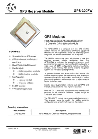
- 1. GPS Receiver Module GPS-320FW
GPS Modules
Fast Acquisition Enhanced Sensitivity
16 Channel GPS Sensor Module
The GPS-320FW is a compact all-in-one GPS module
solution intended for a broad range of Original Equipment
FEATURES Manufacturer (OEM) products, where fast and easy system
integration and minimal development risk is required.
16 parallel channel GPS receiver
4100 simultaneous time-frequency The receiver continuously tracks all satellites in view and
provides accurate satellite positioning data. The
search bins GPS-320FW is optimized for applications requiring good
performance, low cost, and maximum flexibility; suitable for a
SBAS (WAAS, EGNOS) support
wide range of OEM configurations including handhelds,
High Sensitivity: sensors, asset tracking, PDA-centric personal navigation
system, and vehicle navigation products.
-140dBm acquisition sensitivity
-155dBm tracking sensitivity 16 parallel channels and 4100 search bins provide fast
satellite signal acquisition and short startup time. Acquisition
Fast Acquisition: sensitivity of –140dBm and tracking sensitivity of –155dBm
< 5 second hot start offers good navigation performance even in urban canyons
having limited sky view.
< 60 second cold start
Satellite-based augmentation systems, such as WAAS and
5m CEP accuracy
EGNOS, are supported to yield improved accuracy.
‘F’ Versions Programmable
Both the LVTTL-level and RS232-level serial interface are
provided on the interface connector. Supply voltage of
3.8V~8.0V is supported.
The GPS-320FW module has programmable flash memory.
This enables users to modify the NMEA sentence
configuration and re-flash the firmware in the modem.
Ordering Information
Part Number Description
GPS-320FW GPS Module, Onboard Antenna, Programmable
DS-320-2 Aug ’08 ©2006 RF Solutions Ltd, www.rfsolutions.co.uk Page 1
Tel 01273 898000 Fax 01273 480661
- 2. GPS Receiver Module GPS-320FW
TECHNICAL SPECIFICATIONS
Receiver Type 16 parallel channel, L1 C/A code
Accuracy Position 5m CEP
Velocity 0.1m/sec
Startup Time < 5sec hot start
< 35sec warm start
< 60sec cold start
Signal Reacquisition 1s
Sensitivity -140dBm acquisition
-155dBm tracking
Update Rate 1Hz
2
Dynamics 4G (39.2m/sec )
Operational Limits Altitude < 18,000m or velocity < 515m/s
(COCOM limit, either may be exceeded but not both)
Serial Interface LVTTL level and RS-232 level
Protocol NMEA-0183 V3.01
GPGGA, GPGLL, GPGSA, GPGSV, GPRMC, GPVTG, GPZDA
4800 baud, 8, N, 1
Datum Default WGS-84
User definable
Interface Connector One 1.0mm pitch WTB S/R wafer 87213 SMT R/A type connector
Input Voltage 3.8V ~ 8.0V
Current Consumption < 45mA
Dimension 34mm L x 34mm W x 8.6mm H
Weight: 14g
o o
Operating Temperature -40 C ~ +85 C
Humidity 5% ~ 95%
DS-320-2 Aug ’08 ©2006 RF Solutions Ltd, www.rfsolutions.co.uk Page 2
Tel 01273 898000 Fax 01273 480661
- 3. GPS Receiver Module GPS-320FW
2.30
25.00
34.00
4.20
9.50
2.00
3.30
6.70
PINOUT DESCRIPTION
NOTE: Cable CBA-LS-40M is recommended for simple connection
Pin Number Signal Name Description
1 Ground Power and signal ground
2 Power 3.8V ~ 8.0V DC input
3 Serial Data In 2 Asynchronous serial input at RS-232 level, to input configuration commands
4 Serial Data Out 2 Asynchronous serial output at RS-232 level, to output NMEA message
5 Serial Data In 1 Asynchronous serial input at LVTTL level, to input configuration commands
6 Serial Data Out 1 Asynchronous serial output at LVTTL level, to output NMEA message
Please note: The onboard rechargeable Lithium battery may require an initial charge time of
approximately 8hrs.
DS-320-2 Aug ’08 ©2006 RF Solutions Ltd, www.rfsolutions.co.uk Page 3
Tel 01273 898000 Fax 01273 480661
- 4. GPS Receiver Module GPS-320FW
NMEA Messages
The serial interface protocol is based on the National Marine Electronics Association’s NMEA 0183 ASCII
interface specification. This standard is fully define in “NMEA 0183, Version 3.01” The standard may be
obtained from NMEA, www.nmea.org
GGA - GPS FIX DATA
Time, position and position-fix related data (number of satellites in use, HDOP, etc.).
Format:
$GPGGA,<1>,<2>,<3>,<4>,<5>,<6>,<7>,<8>,<9>,M,<10>,M,<11>,<12>,*<13><CR><LF>
Example:
$GPGGA,104549.04,2447.2038,N,12100.4990,E,1,06,01.7,00078.8,M,0016.3,M,,*5C<CR><LF>
Field Example Description
1 104549.04 UTC time in hhmmss.ss format, 000000.00 ~ 235959.99
2 2447.2038 Latitude in ddmm.mmmm format
Leading zeros transmitted
3 N Latitude hemisphere indicator, ‘N’ = North, ‘S’ = South
4 12100.4990 Longitude in dddmm.mmmm format
Leading zeros transmitted
5 E Longitude hemisphere indicator, 'E' = East, 'W' = West
6 1 Position fix quality indicator
0: position fix unavailable
1: valid position fix, SPS mode
2: valid position fix, differential GPS mode
7 06 Number of satellites in use, 00 ~ 12
8 01.7 Horizontal dilution of precision, 00.0 ~ 99.9
9 00078.8 Antenna height above/below mean sea level, -9999.9 ~ 17999.9
10 0016.3 Geoidal height, -999.9 ~ 9999.9
11 Age of DGPS data since last valid RTCM transmission in xxx format (seconds)
NULL when DGPS not used
12 Differential reference station ID, 0000 ~ 1023
NULL when DGPS not used
13 5C Checksum
Note: The checksum field starts with a ‘*’ and consists of 2 characters representing a hex number. The
checksum is the exclusive OR of all characters between ‘$’ and ‘*’.
DS-320-2 Aug ’08 ©2006 RF Solutions Ltd, www.rfsolutions.co.uk Page 4
Tel 01273 898000 Fax 01273 480661
- 5. GPS Receiver Module GPS-320FW
GLL - LATITUDE AND LONGITUDE, WITH TIME OF POSITION FIX AND STATUS
Latitude and longitude of current position, time, and status.
Format:
$GPGLL,<1>,<2>,<3>,<4>,<5>,<6>,<7>*<8><CR><LF>
Example:
$GPGLL,2447.2073,N,12100.5022,E,104548.04,A,A*65<CR><LF>
Field Example Description
1 2447.2073 Latitude in ddmm.mmmm format
Leading zeros transmitted
2 N Latitude hemisphere indicator, ‘N’ = North, ‘S’ = South
3 12100.5022 Longitude in dddmm.mmmm format
Leading zeros transmitted
4 E Longitude hemisphere indicator, 'E' = East, 'W' = West
5 104548.04 UTC time in hhmmss.ss format, 000000.00 ~ 235959.99
6 A Status, ‘A’ = valid position, ‘V’ = navigation receiver warning
7 A Mode indicator
‘N’ = Data invalid
‘A’ = Autonomous
‘D’ = Differential
‘E’ = Estimated
8 65 Checksum
GSA - GPS DOP AND ACTIVE SATELLITES
GPS receiver operating mode, satellites used for navigation, and DOP values.
Format:
$GPGSA,<1>,<2>,<3>,<3>,<3>,<3>,<3>,<3>,<3>,<3>,<3>,<3>,<3>,<3>,<4>,<5>,<6>*<7><CR><LF>
Example:
$GPGSA,A,3,26,21,,,09,17,,,,,,,10.8,02.1,10.6*07<CR><LF>
Field Example Description
1 A Mode, ‘M’ = Manual, ‘A’ = Automatic
2 3 Fix type, 1 = not available, 2 = 2D fix, 3 = 3D fix
3 26,21,,,09,17,,,,,, PRN number, 01 to 32, of satellite used in solution, up to 12 transmitted
4 10.8 Position dilution of precision, 00.0 to 99.9
5 02.1 Horizontal dilution of precision, 00.0 to 99.9
6 10.6 Vertical dilution of precision, 00.0 to 99.9
7 07 Checksum
DS-320-2 Aug ’08 ©2006 RF Solutions Ltd, www.rfsolutions.co.uk Page 5
Tel 01273 898000 Fax 01273 480661
- 6. GPS Receiver Module GPS-320FW
GSV - GPS SATELLITE IN VIEW
Number of satellites in view, PRN number, elevation angle, azimuth angle, and C/No. Only up to four satellite
details are transmitted per message. Additional satellite in view information is sent in subsequent GSV
messages.
Format:
$GPGSV,<1>,<2>,<3>,<4>,<5>,<6>,<7>,…,<4>,<5>,<6>,<7> *<8><CR><LF>
Example:
$GPGSV,2,1,08,26,50,016,40,09,50,173,39,21,43,316,38,17,41,144,42*7C<CR><LF>
$GPGSV,2,2,08,29,38,029,37,10,27,082,32,18,22,309,24,24,09,145,*7B<CR><LF>
Field Example Description
1 2 Total number of GSV messages to be transmitted
2 1 Number of current GSV message
3 08 Total number of satellites in view, 00 ~ 12
4 26 Satellite PRN number, GPS: 01 ~ 32, SBAS: 33 ~ 64 (33 = PRN120)
5 50 Satellite elevation number, 00 ~ 90 degrees
6 016 Satellite azimuth angle, 000 ~ 359 degrees
7 40 C/No, 00 ~ 99 dB
Null when not tracking
8 7C Checksum
RMC - RECOMMANDED MINIMUM SPECIFIC GPS/TRANSIT DATA
Time, date, position, course and speed data.
Format:
$GPRMC,<1>,<2>,<3>,<4>,<5>,<6>,<7>,<8>,<9>,<10>,<11>,<12>*<13><CR><LF>
Example:
$GPRMC,104549.04,A,2447.2038,N,12100.4990,E,016.0,221.0,250304,003.3,W,A*22<CR><LF>
Field Example Description
1 104549.04 UTC time in hhmmss.ss format, 000000.00 ~ 235959.99
2 A Status, ‘V’ = navigation receiver warning, ‘A’ = valid position
3 2447.2038 Latitude in dddmm.mmmm format
Leading zeros transmitted
4 N Latitude hemisphere indicator, ‘N’ = North, ‘S’ = South
5 12100.4990 Longitude in dddmm.mmmm format
Leading zeros transmitted
6 E Longitude hemisphere indicator, 'E' = East, 'W' = West
7 016.0 Speed over ground, 000.0 ~ 999.9 knots
8 221.0 Course over ground, 000.0 ~ 359.9 degrees
9 250304 UTC date of position fix, ddmmyy format
10 003.3 Magnetic variation, 000.0 ~ 180.0 degrees
11 W Magnetic variation direction, ‘E’ = East, ‘W’ = West
12 A Mode indicator
‘N’ = Data invalid
‘A’ = Autonomous
‘D’ = Differential
‘E’ = Estimated
13 22 Checksum
DS-320-2 Aug ’08 ©2006 RF Solutions Ltd, www.rfsolutions.co.uk Page 6
Tel 01273 898000 Fax 01273 480661
- 7. GPS Receiver Module GPS-320FW
VTG - COURSE OVER GROUND AND GROUND SPEED
Velocity is given as course over ground (COG) and speed over ground (SOG).
Format:
GPVTG,<1>,T,<2>,M,<3>,N,<4>,K,<5>*<6><CR><LF>
Example:
$GPVTG,221.0,T,224.3,M,016.0,N,0029.6,K,A*1F<CR><LF>
Field Example Description
1 221.0 True course over ground, 000.0 ~ 359.9 degrees
2 224.3 Magnetic course over ground, 000.0 ~ 359.9 degrees
3 016.0 Speed over ground, 000.0 ~ 999.9 knots
4 0029.6 Speed over ground, 0000.0 ~ 1800.0 kilometers per hour
5 A Mode indicator
‘N’ = Data invalid
‘A’ = Autonomous
‘D’ = Differential
‘E’ = Estimated
6 1F Checksum
ZDA TIME AND DATE
Format:
$GPZDA,<1>,<2>,<3>,<4>,<5>,<6>*<7><CR><LF>
Example:
$GPZDA,104548.04,25,03,2004,,*6C<CR><LF>
Field Example Description
1 104548.04 UTC time in hhmmss.ss format, 000000.00 ~ 235959.99
2 25 UTC time: day (01 ... 31)
3 03 UTC time: month (01 ... 12)
4 2004 UTC time: year (4 digit year)
5 Local zone hour
Not being output by the receiver (NULL)
6 Local zone minutes
Not being output by the receiver (NULL)
7 6C Checksum
Binary Messages
Please refer to DS-41COM, Binary Message Protocol Guide for detailed descriptions on configuration of the
NMEA string.
DS-320-2 Aug ’08 ©2006 RF Solutions Ltd, www.rfsolutions.co.uk Page 7
Tel 01273 898000 Fax 01273 480661
- 8. GPS Receiver Module GPS-320FW
RF Solutions Ltd.,
Unit 21, Cliffe Industrial Estate,
South Street, Lewes, E Sussex, BN8 6JL. England
Tel +44 (0)1273 898 000 Fax +44 (0)1273 480 661
Email sales@rfsolutions.co.uk http://www.rfsolutions.co.uk
DS-320-2 Aug ’08 ©2006 RF Solutions Ltd, www.rfsolutions.co.uk Page 8
Tel 01273 898000 Fax 01273 480661