2. PART Table of Contents
6
Rules for Equipment and Machinery Certification (2012)
CONTENTS
CHAPTER 1 Surveys After Construction................................................................... 1
Section 1 General ..................................................................................7
Section 2 Hull Structure and Outfitting.................................................13
Section 3 Prime Movers.......................................................................17
Section 4 Propulsion and Maneuvering Systems ................................22
Section 5 Boilers, Pressure Vessels and Fired Equipment .................24
Section 6 Piping Systems ....................................................................27
Section 7 Electrical Systems and Control Equipment..........................33
Section 8 Fire and Safety – Equipment and Systems .........................65
Section 9 Jacking and Associated Systems ........................................68
Section 10 Anchoring System – Symbol Á ...........................................77
ii ABS RULES FOR BUILDING AND CLASSING MOBILE OFFSHORE DRILLING UNITS . 2012
3. PART Chapter 1: Material, Marine Equipment and Machinery Certification
6
CHAPTER 1 Material, Marine Equipment and Machinery
Certification
CONTENTS
SECTION 1 General.................................................................................................... 7
1 Application ..........................................................................................7
1.1 Marine and Propulsion Systems...................................................... 7
1.3 Drilling Equipment ........................................................................... 7
3 Unit Certification..................................................................................8
3.1 Basic Requirements ........................................................................ 8
3.3 Specific Requirements .................................................................... 8
3.5 Angles of Inclination ........................................................................ 9
3.7 Ambient Temperature...................................................................... 9
3.9 Skid Mounted Equipment or Machinery........................................... 9
5 Design Review and Survey of Equipment and Machinery................10
5.1 Design Review .............................................................................. 10
5.3 Survey ........................................................................................... 10
7 Prototype Testing..............................................................................11
9 Type Approval Program ....................................................................11
9.1 Application and Limitations............................................................ 11
9.3 Structural Material ......................................................................... 11
9.5 Mass Produced Machinery ............................................................ 11
9.9 Non-mass Produced Machinery .................................................... 11
9.11 Design and Manufacturing Assessment (AQS, RQS and PQA) .... 11
9.13 Type Examination and/or Testing, and Prototype Testing ............. 12
11 Manufacturer’s Guarantee ................................................................12
11.1 Manufacturer’s Affidavit ................................................................. 12
13 Asbestos ...........................................................................................12
SECTION 2 Hull Structure and Outfitting ............................................................... 13
1 General .............................................................................................13
3 Material for Hull Structure .................................................................13
3.1 Plating and Shapes ....................................................................... 13
3.3 Seamless Steel Pipes or Novel Cast Nodes used as Special or
Primary Application Structure of Legs for Self-Elevating Units ...... 13
3.5 Seamless Steel Pipes used as Secondary Application Structure
of Legs for Self-Elevating Units ..................................................... 13
5 Material for Foundation Structures ...................................................14
7 Helideck Structure.............................................................................14
7.1 Material for Helideck Structure ...................................................... 14
7.3 Unit Certification of Helideck Structure .......................................... 14
ABS RULES FOR BUILDING AND CLASSING MOBILE OFFSHORE DRILLING UNITS . 2012 1
4. 9 Watertight Doors ...............................................................................14
9.1 General..........................................................................................14
9.3 Sliding Watertight Doors ................................................................15
9.5 Dogged Watertight Doors ..............................................................15
TABLE 1 Certification Details – Material for Hull Structure and
Outfitting..................................................................................15
TABLE 2 Certification Details – Watertight Doors and Helideck
Structure..................................................................................16
SECTION 3 Prime Movers ........................................................................................ 17
1 General .............................................................................................17
3 Internal Combustion Engines............................................................17
3.1 Fuel Oil System .............................................................................17
3.3 Turbines for Generators.................................................................17
3.5 Diesel Engines for Generators.......................................................18
3.7 Prime Movers for Propulsion Generators.......................................19
3.9 References ....................................................................................20
5 Survey and Certification....................................................................20
TABLE 1 Certification Details – Prime Movers.......................................21
FIGURE 1 Limiting Curves for Loading 4-stroke Diesel Engines
Step-by-step from No-load to Rated Power as Function
of the Brake Mean Effective Pressure ....................................19
SECTION 4 Propulsion and Maneuvering Systems............................................... 22
1 General .............................................................................................22
3 Materials for Propulsion Equipment..................................................22
5 Survey and Certification....................................................................22
TABLE 1 Certification Details – Propulsion and Maneuvering
Systems ..................................................................................23
SECTION 5 Boilers, Pressure Vessels and Fired Equipment ............................... 24
1 General .............................................................................................24
1.1 Application .....................................................................................24
1.3 Grouping of Boilers and Pressure Vessels ....................................24
3 Materials for Group I Boilers, Heaters, Pressure Vessels and
Heat Exchangers ..............................................................................24
5 Survey and Certification....................................................................25
TABLE 1 Certification Details – Boilers, Pressure Vessels and Fired
Equipment ...............................................................................25
TABLE 2 Pressure Vessels and Heat Exchangers ................................26
TABLE 3 Grouping of Boilers, Pressure Vessels and Fired
Equipment ...............................................................................26
2 ABS RULES FOR BUILDING AND CLASSING MOBILE OFFSHORE DRILLING UNITS . 2012
5. SECTION 6 Piping Systems .................................................................................... 27
1 General .............................................................................................27
3 Pipes .................................................................................................27
3.1 Manufacturer’s Certification........................................................... 27
3.3 Identification .................................................................................. 27
3.5 Plastic Piping................................................................................. 27
5 Piping Components other than Pipes ...............................................28
5.1 Pipe Fittings and Valves ................................................................ 28
5.3 Flexible Hoses............................................................................... 28
5.5 Vent Heads and Pressure/Vacuum Valves.................................... 28
5.7 Gauges, Detectors, and Transmitters............................................ 29
5.9 Fluid Power Cylinders ................................................................... 29
5.11 Pumps ........................................................................................... 29
5.13 Nonstandard Components............................................................. 29
7 Survey and Certification....................................................................29
7.1 Survey and Certification of Pipes .................................................. 29
7.3 Survey and Certification of Piping Components other than
Pipes ............................................................................................. 29
TABLE 1 Certification Details – Piping System Components ................31
TABLE 2 Piping Classes and Certification .............................................32
SECTION 7 Electrical Systems and Control Equipment ....................................... 33
1 General .............................................................................................33
1.1 Insulation Material ......................................................................... 33
1.3 Accessibility................................................................................... 34
3 Plans and Data to Be Submitted.......................................................34
3.1 Rotating Machines of 100 kW and Over ........................................ 34
3.3 Switchboards, Distribution Boards, Controllers, etc....................... 34
5 Rotating Machines ............................................................................34
5.1 General.......................................................................................... 34
5.3 Insulation Resistance Measurement ............................................. 35
5.5 Overload and Overcurrent Capability ............................................ 35
5.7 Dielectric Strength of Insulation..................................................... 36
5.9 Temperature Ratings..................................................................... 36
5.11 Construction and Assembly........................................................... 37
5.13 Lubrication..................................................................................... 37
5.15 Operating and Overspeed Governors for Generator Prime
Movers........................................................................................... 37
5.17 Alternating-Current (AC) Generators............................................. 38
5.19 Direct-Current (DC) Generators .................................................... 39
7 Accumulator Batteries.......................................................................40
7.1 General.......................................................................................... 40
7.3 Construction and Assembly........................................................... 40
9 Switchboards, Distribution Boards, Controllers, etc. ........................40
9.1 General.......................................................................................... 40
9.3 Insulation Resistance Measurement ............................................. 41
ABS RULES FOR BUILDING AND CLASSING MOBILE OFFSHORE DRILLING UNITS . 2012 3
6. 9.5 Dielectric Strength of Insulation .....................................................41
9.7 Construction and Assembly ...........................................................42
9.9 Bus Bars, Wiring and Contacts ......................................................42
9.11 Control and Protective Devices .....................................................43
9.13 Switchboards .................................................................................44
9.15 Motor Controllers and Control Centers ..........................................44
9.17 Battery Systems and Uninterruptible Power Systems (UPS).........45
11 Transformers.....................................................................................46
11.1 General..........................................................................................46
11.3 Temperature Rise ..........................................................................46
11.5 Construction and Assembly ...........................................................46
13 Other Electric and Electronics Devices.............................................47
13.1 Circuit Breakers .............................................................................47
13.3 Fuses.............................................................................................47
13.5 Semiconductor Converters ............................................................47
13.7 Cable Junction Boxes ....................................................................48
15 High Voltage Systems.......................................................................48
15.1 General..........................................................................................48
15.3 Machinery and Equipment .............................................................48
17 Electric Propulsion System ...............................................................49
17.1 General..........................................................................................49
17.3 Machinery and Equipment .............................................................50
19 Survey and Certification....................................................................52
19.1 Generators and Motors ≥ 100 kW (135 hp) intended for
Essential Services .........................................................................52
19.3 Propulsion Generators and Motors ................................................52
19.5 Switchboards .................................................................................52
19.7 Motor Controllers and Control Centers intended for Essential
Services ≥ 100 kW (135 hp) ..........................................................53
19.9 Battery Charging Units ≥ 25 kW, UPS units ≥ 50 kVA, and
Associated Distribution Boards, for Essential, Emergency
or Transitional Source of Power.....................................................53
19.11 Power Transformers ≥ 100 kVA and Converters for High
Voltage Systems over 1 kV, for Essential or Emergency
Source of Power ............................................................................53
19.13 Semiconductor Converters for Propulsion (only for
Self-Propelled Units)......................................................................54
19.15 Propulsion Cables other than Internal Wiring in Control Gears
and Switchboards (only for Self-Propelled Units) ..........................54
19.17 Controls for Electric Propulsion Equipment (only for
Self-Propelled Units)......................................................................54
19.19 High Voltage (HV) Systems – Rotating Machinery ........................54
19.21 High Voltage (HV) Systems – Switchgear and Control-Gear
Assemblies ....................................................................................54
19.23 High Voltage (HV) Systems – Transformers ..................................55
TABLE 1 Certification Details – Electrical Equipment and
Machinery................................................................................56
TABLE 2 Factory Testing Schedule for Generators and Motors
≥ 100 kW (135 hp)...................................................................58
4 ABS RULES FOR BUILDING AND CLASSING MOBILE OFFSHORE DRILLING UNITS . 2012
7. TABLE 3 Dielectric Strength Test for Rotating Machines ......................59
TABLE 4 Limits of Temperature Rise for Air-Cooled Rotating
Machines.................................................................................60
TABLE 5 Nameplates .............................................................................61
TABLE 6 Factory Testing Schedule for Switchboards, Chargers,
Motor Control Centers, and Controllers ..................................62
TABLE 7 Clearance and Creepage Distance for Switchboards,
Distribution Boards, Chargers, Motor Control Centers
and Controllers........................................................................62
TABLE 8 Equipment and Instrumentation for Switchboard....................63
TABLE 9 Temperature Rise for Transformers........................................64
SECTION 8 Fire and Safety – Equipment and Systems ........................................ 65
1 General .............................................................................................65
3 Fire Doors .........................................................................................65
5 Fire-Rated Windows .........................................................................65
7 Gas-Tight Doors................................................................................65
9 Fire and Gas Detection Systems ......................................................65
11 Fire Pumps........................................................................................66
13 Survey and Certification....................................................................66
TABLE 1 Certification Details – Safety Equipment and Systems...........66
SECTION 9 Jacking and Associated Systems....................................................... 68
1 General .............................................................................................68
3 Definitions .........................................................................................68
3.1 Jacking System ............................................................................. 68
3.3 Holding Mechanism....................................................................... 68
3.5 Rack and Pinion Jacking System .................................................. 68
3.7 Yoke and Pin Jacking System ....................................................... 68
3.9 Fixation System............................................................................. 69
3.11 Specified Service Temperature ..................................................... 69
3.13 Jacking Unit Rated Capacity ......................................................... 69
3.15 Lifting Capacity per Leg................................................................. 69
5 Plans and Data to be Submitted .......................................................69
7 Failure Modes and Effects Analysis (FMEA) ....................................69
9 Material .............................................................................................70
9.1 Toughness..................................................................................... 70
11 Strength Analysis ..............................................................................71
13 Mechanical Components ..................................................................73
13.1 Bearings ........................................................................................ 73
13.3 Brakes ........................................................................................... 73
13.5 Flexible Shock Pads ...................................................................... 73
15 Electrical Power System ...................................................................73
17 Hydraulic System ..............................................................................73
19 Control, Monitoring and Alarm System .............................................73
ABS RULES FOR BUILDING AND CLASSING MOBILE OFFSHORE DRILLING UNITS . 2012 5
8. 21 Low Temperature Operation .............................................................74
23 Jacking Systems of Novel Design ....................................................74
25 Survey and Certification....................................................................74
25.1 Inspection and Material Testing .....................................................74
25.3 Prototype Test ...............................................................................75
TABLE 1 Charpy V-Notch (CVN) Impact Requirements for Steel
Materials..................................................................................71
TABLE 2 Certification Details – Jacking and Associated Systems ........76
SECTION 10 Anchoring System – Symbol Á .......................................................... 77
1 General .............................................................................................77
3 Anchoring System – Symbol Á........................................................77
5 Survey and Certification....................................................................77
5.1 Inspection and Material Testing .....................................................77
5.3 Prototype Testing of Anchor Windlass...........................................77
5.5 Certification of Anchoring System Equipment................................78
TABLE 1 Certification Details – Anchoring System for Á Symbol.........78
6 ABS RULES FOR BUILDING AND CLASSING MOBILE OFFSHORE DRILLING UNITS . 2012
9. PART Section 1: General
6
CHAPTER 1 Material, Marine Equipment and Machinery
Certification
SECTION 1 General
1 Application
This Section contains general requirements to certify material for hull structure, equipment and machinery
for hull outfitting, equipment and machinery for marine systems and propulsion system (for self-propelled
drilling units) at manufacturer’s plant (unit certification), prior to onboard installation and testing in a
mobile offshore drilling unit at builder’s yard. The subsequent Sections contain requirements to certify
individual product types.
This Chapter does not cover requirements for optional ABS Class Notations such as ACC or AMCC or
ACCU or AMCCU for automation systems, CDS for drilling systems or DPS for dynamic positioning
systems.
ABS Rules and Guides effective at the time the contract is signed between the owner and builder for the
construction of the mobile offshore drilling unit is to be used for certification of manufacturer’s products.
In addition to the requirements contained in this Chapter, the design requirements given in Parts 3, 4 and 5
and the survey and testing requirements during fabrication, onboard installation, testing after installation,
and final trial given in Sections 7-1-1 through 7-1-8 may need to be considered during the certification of
the manufacturer’s product.
1.1 Marine and Propulsion Systems
Boilers, pressure vessels, heat exchangers, internal combustion engines, turbines, propulsion equipment,
steering gear and other applicable equipment are to be in accordance with the requirements of the ABS
Rules for Building and Classing Steel Vessels (Steel Vessel Rules), except as modified herein.
1.3 Drilling Equipment
Equipment and components used solely for operation of drilling systems and complying with an applicable
recognized standard need not be in accordance with these Rules or the Steel Vessel Rules, except where
specifically stated in these Rules. See 4-1-1/1.1.
1.3.1 CDS Notation (optional)
Drilling systems that have been designed reviewed and surveyed, in accordance with the ABS
Guide for the Certification of Drilling Systems (CDS Guide), will be classed and distinguished in
the Record with the notation CDS.
ABS RULES FOR BUILDING AND CLASSING MOBILE OFFSHORE DRILLING UNITS . 2012 7
10. Part 6 Rules for Equipment and Machinery Certification
Chapter 1 Material, Marine Equipment and Machinery Certification
Section 1 General 6-1-1
1.3.2 Drilling Units without CDS Notation
Where the optional CDS notation is not requested, drilling system equipment and components
complying with an applicable recognized standard, need not to comply with the CDS Guide. Refer
to 4-1-1/1.1.1. Verification of compliance with such standards may include:
• Surveyor verification of manufacturer’s affidavits of compliance, or equivalent documentation,
mainly for equipment and components such as pumps, BOP’s, valves, fittings, or motors,
• Design review and surveys after installation of specific assembled systems or sub-systems
such as high pressure mud and cement piping, choke and kill manifold or hydraulic piping.
The design review will be performed to verify compliance with the applicable recognized
standard specified by the manufacturer.
When equipment or components do not comply with an applicable recognized standard, the
equipment or component is to be fully certified in accordance with the CDS Guide.
3 Unit Certification
3.1 Basic Requirements
The Rules define, to varying degrees, the extent of evaluation required for products to be manufactured
based on the level of criticality of each of those items. There are two basic evaluation constituents:
i) Design review; prototype testing; and
ii) Survey during construction and testing at the plant of manufacture
Where design review is required by the Rules, a letter will be issued by ABS upon satisfactory review of
the plans to evidence the acceptance of the design. In addition to, or independent of, design review, ABS
may require survey and testing of forgings, castings and component parts at the various manufacturers’
plants, as well as survey and testing of the finished product. A report will be issued upon satisfactory
completion of each survey to evidence acceptance of the product. Design review, survey and the issuance
of reports constitute the unit certification of a product.
Where the product is accepted in accordance with Product Quality Assurance (PQA) assessment of ABS
Type Approval Program, survey and testing of the product in presence of a Surveyor is not required.
However, product’s unit certification will be issued by the ABS office having jurisdiction over the
manufacturer. For further details, see 1-1-A2/5.7 of the ABS Rules for Conditions of Classification –
Offshore Units and Structures (Part 1).
Based on the intended service and application, some products do not require certification because they are
not directly related to the scope of classification or because normal practices for their construction within
the industry are considered adequate. Such products may be accepted based on the manufacturers’
documentation on design and quality, which guarantees product’s acceptance for classification provided it
is satisfactorily installed and tested onboard the drilling unit.
In general, surveys during installation onboard the vessel and at trials are required for all items of machinery.
This is not considered a part of the product certification process. For onboard installation and trials, refer to
Part 7 of these Rules.
3.3 Specific Requirements
Sections 2 through 10 of this Chapter describe specific certification requirements for material, marine
equipment and machinery used in following areas:
i) Hull Structure and Outfitting (Section 6-1-2)
ii) Prime Movers (Section 6-1-3)
iii) Propulsion and Maneuvering Systems (Section 6-1-4)
iv) Boilers, Pressure Vessels and Fired Equipment (Section 6-1-5)
v) Pumps and Piping Systems (Section 6-1-6)
vi) Electrical Systems and Control Equipment (Section 6-1-7)
8 ABS RULES FOR BUILDING AND CLASSING MOBILE OFFSHORE DRILLING UNITS . 2012
11. Part 6 Rules for Equipment and Machinery Certification
Chapter 1 Material, Marine Equipment and Machinery Certification
Section 1 General 6-1-1
vii) Fire and Safety – Equipment and Systems (Section 6-1-8)
viii) Jacking System – Self-Elevating Units (Section 6-1-9)
ix) Anchoring System (Section 6-1-10)
3.5 Angles of Inclination
All equipment, machinery and their components intended for essential services, as defined in 4-1-1/3.5, are
to be designed to operate under the inclinations as indicated for each of the conditions listed in 4-1-1/Table 1.
Note: The above requirements do not apply to jacking systems of self-elevating drilling units. Jacking systems are to be
operable at maximum angle of inclination stated in the manufacturer’s specification.
3.7 Ambient Temperature
For drilling units of unrestricted service, all equipment and machinery, and their components intended
for essential services, as defined in 4-1-1/3.5, are to be designed to operate under the ambient temperatures
as indicated for each of the conditions listed in 4-1-1/Table 2.
For drilling units of restricted or special service, the ambient temperature appropriate to the special nature
is to be considered.
3.9 Skid Mounted Equipment or Machinery
Where an equipment or machinery is required to be design reviewed and surveyed in accordance with
subsequent Sections 6-1-3 through 6-1-10 and it is assembled on a skid, the design review and survey at
manufacturer’s facility is required if the skid mounted unit has either of the following:
• Center of gravity height is more than 1.5 m (5 ft) in dry condition, or
• Maximum operating weight is in excess of 10 MT (metric tons) or 22.05 Kips.
3.9.1 Design Review
Design of the skid mounted equipment and machinery, together with structural design calculations,
is to be submitted to ABS for review.
3.9.2 Survey
Surveyor’s attendance is required to verify that the skid mounted equipment/machinery is in
compliance with ABS reviewed design and structural design calculations, and to at least carry out
the following:
i) Verify Material Test Report (MTR) of skid material.
ii) Visual examination of final weldments of skid structure.
iii) Witness load testing of the skid structure lifting lugs or pad-eyes. Load test of the skid is
to be carried out at maximum static load the lifting lugs or pad eyes may be subjected to
during the transportation or installation of the equipment/machinery onboard the unit.
iv) Witness surface Nondestructive Testing (NDT) of skid structure weldments of the lifting
lugs/pad eyes, after completion of the skid structure load test. Magnetic Particle Inspection
(MPI) is recommended for NDT.
v) Verify proper alignment of assembled equipment/machinery components.
vi) Verify proper mechanical and electrical connections.
vii) Witness leak/pressure test, as applicable.
viii) Witness Factory Acceptance Test (FAT) of the equipment/machinery on skid.
ABS RULES FOR BUILDING AND CLASSING MOBILE OFFSHORE DRILLING UNITS . 2012 9
12. Part 6 Rules for Equipment and Machinery Certification
Chapter 1 Material, Marine Equipment and Machinery Certification
Section 1 General 6-1-1
5 Design Review and Survey of Equipment and Machinery
5.1 Design Review
Plans and data required to be submitted for certification of specific equipment and machinery are described
under subsequent Sections 6-1-3 through 6-1-10.
5.3 Survey
Certain equipment and machinery and/or associated components require Surveyor’s attendance at the
manufacturer’s plant during fabrication and testing of the respective product. Satisfactorily completed
survey of the product is to be reported upon, only if the required ABS design review of the product was
completed without any outstanding engineering comment.
During fabrication of equipment, the attending Surveyor is to have access to manufacturers’ facilities and
assembly sites to witness fabrication and/or testing, as required by these Rules. The manufacturer is to
contact the attending Surveyor to make necessary arrangements. If the attending Surveyor finds reason to
recommend repairs or additional surveys, notice will be immediately given to the manufacturer’s
representative so that appropriate action may be taken.
Each manufacturer is required to have an effective quality system which is to be verified by the attending
Surveyor. Unless the manufacturer holds an effective ABS Product Quality Assurance (PQA) Certificate,
Surveyor’s attendance is required, typically for the following purposes.
i) To confirm that the facilities to manufacture, fabricate or repair mechanical or electrical marine
components have and maintain an effective Quality Control Program (QCP) effectively covering
design, procurement, manufacturing and testing, as applicable, and meeting the requirements of a
recognized standard applied to their product.
ii) To qualify or verify welder’s qualifications to the extent deemed necessary by the attending Surveyor.
iii) To qualify or verify welding procedure specifications and corresponding weld procedure qualification
records to the extent deemed necessary by the attending Surveyor.
iv) To verify material certificates/documentation.
v) To survey fit-up prior to major weldments.
vi) To survey final weldments.
vii) To witness, as far as deemed necessary, Non-Destructive Testing (NDT) of welds and to review
records of NDT.
viii) To verify dimensions are the same as shown on approved drawings.
ix) To check dimensional tolerances and alignment of mating surfaces.
x) To witness prototype testing of jacking gear system subject to such testing in accordance with
these Rules.
xi) To witness pressure and/or proof-load testing of equipment components and as a unit, as applicable
and as called for in the fabrication procedures.
xii) To witness final testing and functional testing of subassemblies and completed units, as called for
in the fabrication procedures.
xiii) To carry out other surveys as agreed upon during prefabrication meeting, including the Factory
Acceptance Test (FAT).
Surveys required for certification of specific equipment are described under subsequent Sections 6-1-2
through 6-1-10.
10 ABS RULES FOR BUILDING AND CLASSING MOBILE OFFSHORE DRILLING UNITS . 2012
13. Part 6 Rules for Equipment and Machinery Certification
Chapter 1 Material, Marine Equipment and Machinery Certification
Section 1 General 6-1-1
7 Prototype Testing
Where prototype testing is required by these Rules, Surveyor is to witness the prototype testing at the plant
of manufacture, and report upon the test results. Results of the prototype testing endorsed by the Surveyor
are to be submitted to respective Engineering office to supplement the completed design review or where
type testing was done in lieu of design review. Subsequent testing of the product that has been already
prototype tested may be carried out by the manufacturer and test results accepted based upon previously
completed prototype testing of the product.
Subsequent Sections 6-1-2 through 6-1-10 describe products that may be required to be subjected to
prototype testing.
9 Type Approval Program
The process of the ABS Type Approval program is explained in 1-1-4/9.7 and 1-1-A2 of the ABS Rules for
Conditions of Classification – Offshore Units and Structures (Part 1).
9.1 Application and Limitations
For reference purposes, applicable Tables in subsequent Sections contain examples of the limitations of the
Program for marine equipment and machinery. Products that are not listed in the Tables may be considered
for inclusion in the Type Approval Program on a case-by-case basis. The manufacturer is to contact the
nearest ABS office for advice.
9.3 Structural Material
Structural material, including certain piping material used for structural support purposes (see Section 6-1-2
of these Rules), is required to be certified in accordance with these Rules by a Surveyor attending the ABS
approved steel mill. Type Approval Program is not applicable to certification of structural material.
9.5 Mass Produced Machinery
Products that are mass produced and therefore, can be consistently manufactured to the same design and
specification, and that are not required to be unit certified by a Surveyor at manufacturer’s plant in
accordance with this Chapter, may be Type Approved in accordance with the ABS Type Approval Program.
The ABS Type Approval Program is a voluntary option for the demonstration of the compliance of a
product with the Rules or other recognized standards. The ABS Type Approval Program generally covers
Product Type Approval [1-1-4/9.7.3 of the ABS Rules for Conditions of Classification – Offshore Units
and Structures (Part 1)], but is also applicable for a more expeditious procedure towards unit certification,
as specified in 1-1-4/9.7.2 of the above-referenced Part 1 and 6-1-1/3 of these Rules.
9.9 Non-mass Produced Machinery
Non-mass produced critical machinery, such as propulsion boilers, slow speed diesel engines, turbines,
steering gears, and similar critical items are to be individually unit certified in accordance with the
procedure described in 6-1-1/3.1. However, consideration will be given to granting Type Approval to such
machinery in the categories of Acceptable Quality System (AQS) and Recognized Quality System (RQS).
The category of Product Quality Assurance (PQA) will not normally be available for all products, and such
limitations are indicated in the respective Tables of subsequent Sections. In each instant where Type
Approval is granted, in addition to quality assurance and quality control assessment of the manufacturing
facilities, ABS will require some degree of product specific survey during manufacture.
9.11 Design and Manufacturing Assessment (AQS, RQS and PQA)
The Tables in subsequent Sections contain the requirements for Type Approval of the listed components
and equipment with regard to Product Design Assessment (Design Review and Prototype Testing) and
Manufacturing Assessment (PQA option only). Manufacturing Assessment in the categories of Acceptable
Quality System (AQS) or Recognized Quality System (RQS) may be carried out on any product and
therefore, are not shown on the Tables.
ABS RULES FOR BUILDING AND CLASSING MOBILE OFFSHORE DRILLING UNITS . 2012 11
14. Part 6 Rules for Equipment and Machinery Certification
Chapter 1 Material, Marine Equipment and Machinery Certification
Section 1 General 6-1-1
9.13 Type Examination and/or Testing, and Prototype Testing
Any product requested to be Type Approved is to be subjected to type examination and testing in the presence
of the Surveyor attending the manufacturer’s plant for initial assessment. Therefore, the type exam or type
testing of the initial product required by the Type Approval Program, as referenced in 1-1-4/9.7 and Appendix
1-1-A2 of the ABS Rules for Conditions of Classification – Offshore Units and Structures (Part 1), are not
indicated under the applicable Tables contained in subsequent Sections.
Where prototype test is required as indicated in the applicable Tables of this Chapter, the type examination
and/or testing of the initial product for Type Approval may be waived, provided the design or fabrication
process of the product remain unchanged since it was prototype tested.
11 Manufacturer’s Guarantee
All products manufactured for installation onboard a classed unit are expected to operate in a safe and
appropriate manner, and guaranteed by the manufacturer to do so, as long as the recommended
maintenance procedure of the product is adhered to by the owner/operator.
11.1 Manufacturer’s Affidavit
Where a manufactured product does not require Surveyor attendance for unit certification, Surveyor’s
attendance is not requested by the client, or the product is not certified under the ABS Type Approval
Program, manufacturer’s guarantee for product’s compliance with a recognized standard may be accepted
by ABS, provided the product as installed onboard satisfy the classification requirements of the drilling
unit. Where requested by ABS, manufacturer’s affidavit is to be submitted.
13 Asbestos
Installation of material, which contains asbestos, is prohibited.
12 ABS RULES FOR BUILDING AND CLASSING MOBILE OFFSHORE DRILLING UNITS . 2012
15. PART Section 2: Hull Structure and Outfitting
6
CHAPTER 1 Material, Marine Equipment and Machinery
Certification
SECTION 2 Hull Structure and Outfitting
1 General
Materials used for hull construction and hull outfitting for which certification is required as indicated in
6-1-2/Table 1 are to be produced, tested, and certified in accordance with the ABS Rules for Materials and
Welding (Part 2), as applicable and this Chapter.
Where material other than steel is used, material suitability and test results per the International Code for
Application of Fire Test Procedures (FTP Code) is to be acceptable to ABS.
3 Material for Hull Structure
3.1 Plating and Shapes
Materials of plating and shapes used for construction of drilling unit’s main hull structure are to be produced
by an ABS approved mill and certified by an ABS Surveyor.
Selection of structural materials is to be in accordance with applicable Sections of Part 3, Chapter 2.
Certification of these materials is to be in accordance with the ABS Rules for Materials and Welding (Part 2),
as applicable. Part 2, Appendix 1 has a complete listing of indicated designations for various tests called out
by Chapters 1 and 2 of the ABS Rules for Materials and Welding (Part 2).
3.3 Seamless Steel Pipes or Novel Cast Nodes used as Special or Primary Application
Structure of Legs for Self-Elevating Units
Seamless steel pipes or novel-design cast nodules used either as special or as primary application structures of
tubular leg members are to be produced by an ABS approved mill and certified by an ABS Surveyor.
Selection of structural materials is to be in accordance with Section 3-2-3. Definitions of special and primary
application structure of legs on a self-elevating unit are in Section 3-2-3 of these Rules.
Certification of these materials is to be in accordance with the ABS Rules for Materials and Welding (Part 2),
as applicable. Part 2, Appendix 1 has a complete listing of indicated designations for various tests called out
by Chapters 1 and 2 of the ABS Rules for Materials and Welding (Part 2).
3.5 Seamless Steel Pipes used as Secondary Application Structure of Legs for Self-
Elevating Units
Seamless steel pipes used as Secondary Application Structure of legs on a self-elevating unit need not be
produced by an ABS approved mill and certified by an ABS Surveyor. However, the selection of such
structural materials is to be in accordance with Section 3-2-3, and the Material Test Report (MTR) of each
member is to be available to the Surveyor before being installed onboard.
ABS RULES FOR BUILDING AND CLASSING MOBILE OFFSHORE DRILLING UNITS . 2012 13
16. Part 6 Rules for Equipment and Machinery Certification
Chapter 1 Material, Marine Equipment and Machinery Certification
Section 2 Hull Structure and Outfitting 6-1-2
5 Material for Foundation Structures
In general, major foundations include but not limited to the foundations for the following equipment or
machinery:
• Pedestal cranes for loading/unloading of equipment and personnel.
• Anchoring or mooring system winches.
• Fairleads.
Material used for major foundation structures are to be in accordance with ABS approved drawings. In lieu of
unit certification, manufacturer’s Material Test Report (MTR) for materials used for major foundations and
tested in accordance with the ABS Rules for Materials and Welding (Part 2), as applicable, may be accepted
by the Surveyor. The Material Test Report (MTR) of each member is to be available to the Surveyor before
being installed onboard.
All major foundation structures affect classification of a drilling unit and are required to be design reviewed
and surveyed during fabrication and installation.
7 Helideck Structure
Certification of helideck structure is required as indicated in 6-1-2/Table 2 and a helideck structure is to be
designed in accordance with Part 3 of these Rules and certified in accordance with this Chapter.
7.1 Material for Helideck Structure
The helideck structure deck plating and its main support structural members fabricated out of steel or other
acceptable material need not be produced by an ABS approved mill and certified by an ABS Surveyor.
However, the selection of such structural materials is to be in accordance with Section 3-2-3, and the Material
Test Report (MTR) of each member is to be available to the Surveyor before being installed onboard.
7.3 Unit Certification of Helideck Structure
If the helideck structure is fabricated within the builder’s yard where the drilling unit is being built, design
and fabrication of the helideck structure is to be in accordance with Part 3 of these Rules, and built in
presence of and to the satisfaction of the Surveyor. In such case, the helideck may be considered as part of the
rig’s construction.
If the helideck structure is fabricated away from the builder’s yard where the drilling unit is being built,
design and fabrication of the helideck structure is to be in accordance with Part 3 of these Rules, and built in
presence of and to the satisfaction of the Surveyor. In such case, the helideck is to be treated as a product to
be unit certified.
9 Watertight Doors
Certification of watertight doors is required as indicated in 6-1-2/Table 2 and they are to be designed,
fabricated and tested in accordance with this Section.
9.1 General
Watertight doors are to be designed to withstand water pressure to a head up to the bulkhead deck or freeboard
deck respectively. A prototype pressure test is to be conducted for each type and size of door to be installed on
the unit at a test pressure corresponding to at least the head required for the intended location. The prototype test
is to be carried out at the manufacturer’s plant. The installation method and procedure for fitting the door on
board is to correspond to that of the prototype test. Large doors or hatches of a design and size that would make
pressure testing impracticable may be exempted from the prototype pressure test, provided that it is
demonstrated by calculations that the doors or hatches maintain watertightness at the design pressure.
14 ABS RULES FOR BUILDING AND CLASSING MOBILE OFFSHORE DRILLING UNITS . 2012
17. Part 6 Rules for Equipment and Machinery Certification
Chapter 1 Material, Marine Equipment and Machinery Certification
Section 2 Hull Structure and Outfitting 6-1-2
Watertight doors are to be of ample strength for the water pressure to which they may be subjected.
Doorframes are to be carefully fitted to the bulkheads; where liners are required, the material is to be not
readily injured by heat or by deterioration.
Reference is also made to 3-3-2/5.3 with regard to watertight integrity of the unit.
9.3 Sliding Watertight Doors
Sliding watertight doors are to be unit certified. Sliding watertight doors are to be manufactured in
accordance with ABS approved drawings, surveyed and tested in presence of and to the satisfaction of the
Surveyor. Sliding doors are to be carefully fitted to the frames.
Sliding doors are to be tested for operation at the manufacturer’s plant. Hydrostatic testing of sliding doors
as indicated in 6-1-2/9.1 is also to be carried out at the manufacturer’s plant
Fabrication, hydrostatic testing and satisfactory operational testing of the doors are to be witnessed by a
Surveyor and reported upon.
9.5 Dogged Watertight Doors
Non-sliding dogged watertight doors are to be certified. Dogged watertight doors are to be manufactured in
accordance with ABS approved drawings and subjected to type testing.
Dogged watertight doors are to be subjected to a hydrostatic test as indicated in 6-1-2/9.1 at the manufacturer’s
plant.
Fabrication, hydrostatic testing and satisfactory operational testing of the doors during the prototype testing
are to be witnessed by a Surveyor and reported upon. Dogged doors that have satisfactorily completed its
type-testing may then be certified without unit certification, preferably under the ABS Type Approval Program.
TABLE 1
Certification Details – Material for Hull Structure and Outfitting (2012)
Design Prototype Material ABS Approved Manufacturer’s
Material
Review (1) Testing Test (2) Mill (3) MTR (4)
Steel Plating for Hull Structure. – – X X X
Shapes for Hull Structure. – – X X X
Seamless Steel Piping used as Special or Primary
Application Structure of Legs for Self-Elevating – – X X X
Units.
Novel Cast Nodes of Legs for Self-Elevating Units. – – – X X
Seamless Steel Piping used as Secondary Application
– – – – X
Structure of Legs for Self-Elevating Units.
Seamless Steel Piping used as Appurtenant
– – – – X
Structures.
Helideck Structure Material – – – – X
Foundation Structures - Primary Application
– – X X X
Structures
Watertight Door Plating and Stiffeners – – – – X
Notes:
1 Design review of material is not required. However, structural drawings of the unit are to indicate material selected
in accordance with these Rules and to be used for construction.
2 Material tests witnessed by Surveyor.
3 Material is to be produced at an ABS approved mill under a satisfactory Quality Assurance program.
4 Material Test Report (MTR) is to be available to the Surveyor upon request.
ABS RULES FOR BUILDING AND CLASSING MOBILE OFFSHORE DRILLING UNITS . 2012 15
18. Part 6 Rules for Equipment and Machinery Certification
Chapter 1 Material, Marine Equipment and Machinery Certification
Section 2 Hull Structure and Outfitting 6-1-2
TABLE 2
Certification Details – Watertight Doors and Helideck Structure (2012)
Watertight Doors and Design Prototype Material Survey at Unit
PQA (5)
Helideck Structure Review (1) Testing Test (2) Vendor Certification
Sliding Watertight Door. X X X X X N
Dogged Watertight Door X (3) X X – – O
(4) (4) (4)
Helideck Structure X – X X X N
Notes:
1 Design review by ABS is required for unit certification. Where Type Approval is allowed and requested, Product
Design Assessment (PDA) by ABS is required.
2 Material Test Report (MTR) is to be available to the Engineer and/or Surveyor upon request.
3 Design review of dogged watertight doors will be carried out based on builder’s submitted drawings. No specific
design review required for fabrication.
4 See 6-1-2/7 of these Rules.
5 In general, unit certification in accordance with PQA is optional. Refer to 1-1-A2/5.5 of the ABS Rules for
Conditions of Classification – Offshore Units and Structures (Part 1). Column “PQA” is applicable to PQA only,
and the “O” marks in the Table indicate where a product may be allowed to be unit certified in accordance with
PQA. A “–“ mark indicates that the product has no requirement in these Rules. An “N” mark indicates that ABS
does not allow unit certification in accordance with a PQA Type Approval.
Symbols used in Tables
N - Not Allowed. Unit certification by Surveyor after attending required surveys at manufacturer’s plant.
O - Optional.
X - Required.
– - Not Applicable or Not Required
16 ABS RULES FOR BUILDING AND CLASSING MOBILE OFFSHORE DRILLING UNITS . 2012
19. PART Section 3: Prime Movers
6
CHAPTER 1 Material, Marine Equipment and Machinery
Certification
SECTION 3 Prime Movers
1 General
Prime movers (diesel engines and their turbochargers, gas turbines, steam turbines) for which certification
is required as indicated in 6-1-3/Table 1 are to be designed, constructed, tested, certified and installed in
accordance with Part 4, Chapter 2 of the Steel Vessel Rules and this Chapter.
3 Internal Combustion Engines
3.1 Fuel Oil System
3.1.1 Injection Piping.
All external high pressure fuel delivery lines between the high-pressure fuel pumps and fuel
injectors are to be protected with a jacketed piping system capable of containing fuel from a high-
pressure line failure. A jacketed pipe incorporates an outer pipe into which the high-pressure fuel
pipe is placed, forming a permanent assembly. Metallic hose of an approved type may be accepted
as the outer pipe, where outer piping flexibility is required for the manufacturing process of the
permanent assembly. The jacketed piping system is to include means for collection of leakages
and arrangements are to be provided for an alarm to be given of a fuel line failure.
3.1.2 Fuel Oil Return Piping.
When the peak to peak pressure pulsation in the fuel oil return piping from the injectors exceeds
20 bar (20.5 kgf/cm2, 285 psi), jacketing of the return pipes is also required.
3.1.3 Hot Surfaces
All surfaces with temperatures above 220°C, which may be impinged as a result of a fuel system
failure, are to be properly insulated with non-combustible materials that are impervious to oil.
Insulation material not impervious to oil is to be encased in sheet metal or an equivalent impervious
sheath.
Oil fuel lines are to be screened or otherwise suitably protected to avoid, as far as practicable, oil
spray or oil leakages onto hot surfaces, into machinery air intakes, or other sources of ignition.
The number of joints in such piping systems is to be kept to a minimum.
3.3 Turbines for Generators
Gas-turbine prime mover driving generators are to meet the applicable requirements in Section 4-2-3 of the
Steel Vessel Rules and in addition are to comply with the following requirements. For rotating machines
intended solely for drilling operations, see 6-1-1/1.3 and Section 4-1-2 of these Rules.
3.3.1 Operating Governor
An effective operating governor is to be fitted on prime movers driving main or emergency electric
generators and is to be capable of automatically maintaining speed within the following limits.
Special consideration will be given when an installation requires different characteristics.
ABS RULES FOR BUILDING AND CLASSING MOBILE OFFSHORE DRILLING UNITS . 2012 17
20. Part 6 Rules for Equipment and Machinery Certification
Chapter 1 Material, Marine Equipment and Machinery Certification
Section 3 Prime Movers 6-1-3
3.3.1(a) Transient Frequency Variations. The transient frequency variations in the electrical network,
when running at the indicated loads below, are to be within ±10% of the rated frequency when:
i) Running at full load (equal to rated output) of the generator and the maximum electrical
step load is suddenly thrown off:
In the case when a step load equivalent to the rated output of a generator is thrown off, a
transient frequency variation in excess of 10% of the rated frequency may be acceptable,
provided the overspeed protective device fitted in addition to the governor, as required by
6-1-3/3.3.2, is not activated.
ii) Running at no load and 50% of the full load of the generator is suddenly thrown on
followed by the remaining 50% load after an interval sufficient to restore the frequency to
steady state.
In all instances, the frequency is to return to within ±1% of the final steady state condition
in no more than five seconds.
3.3.1(b) Frequency Variations in Steady State. The permanent frequency variation is to be within
±5% of the rated frequency at any load between no load and full load.
3.3.1(c) Emergency Generator Prime Movers. For gas turbines driving emergency generators,
the requirements of 6-1-3/3.3.1(a) and 6-1-3/3.3.1(b) are to be met. However, for the purpose of
6-1-3/3.3.1(a)ii), where the sum of all loads that can be automatically connected is larger than
50% of the full load of the emergency generator, the sum of these loads is to be used as the first
applied load.
3.3.2 Overspeed Governor
In addition to the normal operating governor, an overspeed governor is to be fitted which will trip
the turbine throttle when the rated speed is exceeded by more than 15%. Provision is to be made
for hand tripping. See 6-1-7/5.13 for pressure-lubricated machines.
3.3.3 Power Output of Gas Turbines
To satisfy the requirements of 4-3-2/3.1, the required power output of gas turbine prime movers for
drilling unit main service generator sets is to be based on the maximum expected inlet air temperature.
3.5 Diesel Engines for Generators
Diesel-engine prime movers are to meet the applicable requirements in Section 4-2-1 of the Steel Vessel
Rules and, in addition, are to comply with the following requirements. For rotating machines intended solely
for drilling operations, see 6-1-1/1.3 and Section 4-1-2 of these Rules.
3.5.1 Operating Governor
An effective operating governor is to be fitted on prime movers driving main or emergency electric
generators and is to be capable of automatically maintaining the speed within the following limits.
Special consideration will be given when an installation requires different characteristics.
3.5.1(a) Transient Frequency Variations. The transient frequency variations in the electrical network,
when running at the indicated loads below, are to be within ±10% of the rated frequency when:
i) Running at full load (equal to rated output) of the generator and the maximum electrical
step load is suddenly thrown off,
In the case when a step load equivalent to the rated output of a generator is thrown off, a
transient frequency variation in excess of 10% of the rated frequency may be acceptable,
provided the overspeed protective device, fitted in addition to the governor, as required by
6-1-3/3.5.2, is not activated.
ii) Running at no load and 50% of the full load of the generator is suddenly thrown on
followed by the remaining 50% load after an interval sufficient to restore the frequency to
steady state.
In all instances, the frequency is to return to within ±1% of the final steady state condition
in no more than five seconds.
18 ABS RULES FOR BUILDING AND CLASSING MOBILE OFFSHORE DRILLING UNITS . 2012
21. Part 6 Rules for Equipment and Machinery Certification
Chapter 1 Material, Marine Equipment and Machinery Certification
Section 3 Prime Movers 6-1-3
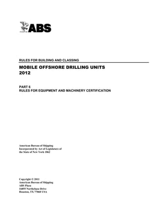
iii) Where the electrical power system is fitted with a power management system and sequential
starting arrangements, the application of loads in multiple steps of less than 50% of rated
load in 6-1-3/3.5.1(a)ii) above may be permitted, provided it is in accordance with
6-1-3/Figure 1. The details of the power management system and sequential starting
arrangements are to be submitted and its satisfactory operation is to be demonstrated to
the Surveyor.
FIGURE 1
Limiting Curves for Loading 4-stroke Diesel Engines
Step-by-step from No-load to Rated Power as Function
of the Brake Mean Effective Pressure (2012)
3.5.1(b) Frequency Variations in Steady State. The permanent frequency variation is to be
within ±5% of the rated frequency at all loads between no load and full load.
3.5.1(c) Emergency Generator Prime Movers. For prime movers driving emergency generators,
the requirements of 6-1-3/3.5.1(a) and 6-1-3/3.5.1(b) above are to be met. However, for the purpose
of 6-1-3/3.5.1(a)ii), where the sum of all loads that can be automatically connected is larger than
50% of the full load of the emergency generator, the sum of these loads is to be used as the first
applied load.
3.5.2 Overspeed Governor
In addition to the normal operating governor, each auxiliary diesel engine having a maximum
continuous output of 220 kW and over is to be fitted with a separate overspeed device so adjusted
that the speed cannot exceed the maximum rated speed by more than 15%. Provision is to be made
for hand tripping. See 6-1-7/5.13 for pressure-lubricated machines.
3.7 Prime Movers for Propulsion Generators
In addition to 6-1-3/3.3 and 6-1-3/3.5, prime movers for propulsion generators are to comply with the
following requirements:
3.7.1 Capability
The prime mover rated output are to have adequate overloading and build-up capacity for
supplying the power which is necessary during transitional changes in operating conditions of the
electrical equipment. When maneuvering from full propeller speed ahead to full propeller speed
astern with the unit making full way ahead, the prime mover is be capable of absorbing a
proportion of the regenerated power without tripping due to overspeed.
ABS RULES FOR BUILDING AND CLASSING MOBILE OFFSHORE DRILLING UNITS . 2012 19
22. Part 6 Rules for Equipment and Machinery Certification
Chapter 1 Material, Marine Equipment and Machinery Certification
Section 3 Prime Movers 6-1-3
3.7.2 Speed Control
Prime movers of any type are to be provided with a governor capable of maintaining the preset
steady speed within a range not exceeding 5% of the rated full-load speed for load changes from
full-load to no-load.
3.7.3 Manual Controls
Where the speed control of the propeller requires speed variation of the prime mover, the governor
is to be provided with means for local manual control as well as for remote control. For turbines
driving AC propulsion generators, where required by the system of control, the governor is to be
provided with means for local hand control as well as remote adjustment from the control station.
3.7.4 Parallel Operation
In case of parallel operation of generators, the governing system is to permit stable operation to be
maintained over the entire operational speed range of the prime movers.
3.7.5 Protection for Regenerated Power
Braking resistors or ballast consumers are to be provided to absorb excess amounts of regenerated
energy and to reduce the speed of rotation of the propulsion motor. These braking resistors or
ballast consumers are to be located external to the mechanical and electric rotating machines.
Alternatively, the amount of regenerated power may be limited by the action of the control system.
3.9 References
3.9.1 Angles of Inclination
For requirements covering angles of inclination for design condition, refer to 6-1-1/3.5 and
4-1-1/Table 1.
3.9.2 Alarms and Safeguards for Emergency Diesel Engines
For requirements covering alarms and safeguards for emergency diesel engines, refer to 4-3-2/5.17.
3.9.3 Prime Mover driving Emergency Generator
For requirements covering emergency generator prime movers, refer to 4-3-2/5.5.2.
3.9.4 Engine Support Systems
For requirements covering support systems for internal combustion engines, refer to 4-2-5/7 (fuel
oil system), 4-2-6/1 (lubricating oil system), 4-2-6/9 (starting-air system), 4-2-6/11 (cooling-water
system) and 4-2-6/13 (exhaust system).
3.9.5 Internal Combustion Engines designed for Drilling Operations
For requirements covering internal combustion engines solely for drilling operations, refer to 4-1-2/3.
3.9.6 Internal Combustion Engines installed in Hazardous Areas
For requirements covering the installation of internal combustion engines in hazardous areas, refer
to 4-3-6/11.
5 Survey and Certification
Where required, all material, type-testing and unit certification is to be carried out, in presence of and to
the satisfaction of the Surveyor, at manufacturer’s plant and reported upon before installation onboard. The
“X” marks on 6-1-3/Table 1 show the extent of ABS unit certification services required for each type of
prime mover and its associated equipment. Where a product does not require unit certification, Surveyor
attendance is optional, and the product is to be designed and fabricated to satisfy a recognized industrial
standard and the manufacturer’s specification.
20 ABS RULES FOR BUILDING AND CLASSING MOBILE OFFSHORE DRILLING UNITS . 2012
23. Part 6 Rules for Equipment and Machinery Certification
Chapter 1 Material, Marine Equipment and Machinery Certification
Section 3 Prime Movers 6-1-3
TABLE 1
Certification Details – Prime Movers (2012)
Design Prototype Material Survey at Unit
Prime Movers PQA (7)
Review (1) Testing (4) Test (5) Vendor (6) Certification
Diesel engines with cylinder bore
X X X X X N
> 300 mm
Diesel engines; steam turbines; gas
turbines; ≥ 100 kW (135 hp), intended X X X X X O
for essential services
Diesel engines; steam turbines; gas
turbines; < 100 kW (135 hp), intended XTA – – – – –
for essential services
Diesel engines; steam turbines; gas
turbines; ≥ 100 kW (135 hp), but not X (2) – – – – –
intended for essential services
Diesel engines; steam turbines; gas
turbines; < 100 kW (135 hp), but not XTA – – – – –
intended for essential services
Internal combustion engines used solely
X (3) – – – – –
for drilling operations
Turbochargers for engines ≥ 100 kW
X X X X X O
(135 hp) and bore ≥ 300 mm (11.8 in.)
Turbochargers for engines ≥ 100 kW
X X – – X O
(135 hp) and bore < 300 mm (11.8 in.)
Governors for generator prime movers – X – – – –
Notes:
1 Design review by ABS is required for unit certification. Where Type Approval is allowed and requested, Product
Design Assessment (PDA) by ABS is required.
2 Design review by ABS is required for compliance with requirements of safety features (see 4-1-2/1 of these
Rules).
3 Design review by ABS is required to verify safety provisions (see 4-1-2/3 of these Rules).
4 Material tests witnessed by Surveyor.
5 Material Test Report (MTR) is to be available to the Engineer and/or Surveyor upon request
6 Survey at the plant of manufacture including witnessing Factory Acceptance Test (FAT) on production unit.
7 In general, unit certification in accordance with PQA is optional. Refer to 1-1-A2/5.5 of the ABS Rules for
Conditions of Classification – Offshore Units and Structures (Part 1). Column “PQA” is applicable to PQA only,
and the “O” marks in the Table indicate where a product may be allowed to be unit certified in accordance with
PQA. A “–“ mark indicates that the product has no requirement in these Rules. An “N” mark indicates that ABS
does not allow unit certification in accordance with a PQA Type Approval.
Symbols used in Table
N - Not Allowed. Unit certification by Surveyor after attending required surveys at manufacturer’s plant.
O - Optional.
X - Required.
TA
X - Required only if Type Approval is requested.
– - Not Applicable or Not Required
ABS RULES FOR BUILDING AND CLASSING MOBILE OFFSHORE DRILLING UNITS . 2012 21
24. PART Section 4: Propulsion and Maneuvering Systems
6
CHAPTER 1 Material, Marine Equipment and Machinery
Certification
SECTION 4 Propulsion and Maneuvering Systems
1 General
Propulsion and maneuvering machinery (propulsion shafts and its components, propulsion gears and
clutches, propellers, propulsion and positioning thrusters and steering gears) for which certification is required
as indicated in 6-1-4/Table 1 are to be designed, constructed, tested, certified and installed in accordance
with Part 4, Chapter 3 of the Steel Vessel Rules and this Chapter.
3 Materials for Propulsion Equipment
Materials for the following equipment intended for main propulsion installation are to be tested in accordance
with the requirements of Chapter 3 of the ABS Rules for Materials and Welding (Part 2): thrust shafts, line
shafts, propeller shafts, shafting for propulsion generators and motors, coupling bolts, and in the case of
direct-connected turbine-driven propulsion generators, fan shrouds, centering and retaining rings.
Major castings or built-up parts such as frames, spiders and end shields are to be surface-inspected and the
welding is to be in accordance with requirements of Chapter 4 of the above referenced Part 2.
5 Survey and Certification
Where required, all material, type-testing and unit certification is to be carried out, in presence of and to
the satisfaction of the Surveyor, at manufacturer’s plant and reported upon before installation onboard. The
“X” marks on 6-1-4/Table 1 show the extent of ABS unit certification services required for each type of
prime mover and its associated equipment. Where a product does not require unit certification, Surveyor
attendance is optional, and the product is to be designed and fabricated to satisfy a recognized industrial
standard and the manufacturer’s specification.
22 ABS RULES FOR BUILDING AND CLASSING MOBILE OFFSHORE DRILLING UNITS . 2012
25. Part 6 Rules for Equipment and Machinery Certification
Chapter 1 Material, Marine Equipment and Machinery Certification
Section 4 Propulsion and Maneuvering Systems 6-1-4
TABLE 1
Certification Details – Propulsion and Maneuvering Systems (2012)
Design Prototype Material Survey at Unit
Propulsion and Maneuvering Systems PQA (4)
Review (1) Testing Test (2) Vendor (3) Certification
Propulsion shafts, couplings, coupling
X – X X X N
bolts
Cardan shafts, standard couplings and
X – X X X O
coupling bolts
Gears and Clutches ≥ 5590 kW (7500 hp) X – X X X N
Gears and Clutches ≥ 100 kW (135 hp) X – X X X O
Gears and Clutches < 100 kW (135 hp) XTA – – – – –
Propellers, fixed and controllable pitch X – X X X N
Thrusters for propulsion or
X – X X X N
Dynamic Positioning System (DPS) (5)
Steering gears X – X X X –
Athwartship thrusters X – X X X O
Notes:
1 Design review by ABS is required for unit certification. Where Type Approval is allowed and requested, Product
Design Assessment (PDA) by ABS is required.
2 Material tests witnessed by Surveyor.
3 Survey at the plant of manufacture including witnessing Factory Acceptance Test (FAT) on production unit.
4 In general, unit certification in accordance with PQA is optional. Refer to 1-1-A2/5.5 of the ABS Rules for
Conditions of Classification – Offshore Units and Structures (Part 1) . Column “PQA” is applicable to PQA only,
and the “O” marks in the Table indicate where a product may be allowed to be unit certified in accordance with
PQA. A “–“ mark indicates that the product has no requirement in these Rules. An “N” mark indicates that ABS
does not allow unit certification in accordance with a PQA Type Approval.
5 For certification of dynamic positioning thrusters (units with DPS notation), refer to 4-3-5/13 of the Steel Vessel Rules.
Symbols used in Table
N - Not Allowed. Unit certification by Surveyor after attending required surveys at manufacturer’s plant.
O - Optional.
X - Required.
XTA - Required only if Type Approval is requested.
– - Not Applicable or Not Required
ABS RULES FOR BUILDING AND CLASSING MOBILE OFFSHORE DRILLING UNITS . 2012 23
26. PART Section 5: Boilers, Pressure Vessels and Fired Equipment
6
CHAPTER 1 Marine Equipment and Machinery Certification
SECTION 5 Boilers, Pressure Vessels and Fired Equipment
1 General
Boilers, fired and unfired heaters, pressure vessels and heat exchangers for which certification is required
as indicated in 6-1-5/Table 1 are to be designed, constructed, tested, certified and installed in accordance
with Part 4, Chapter 4 of the Steel Vessel Rules and this Chapter.
All boilers, heaters, pressure vessels and heat exchangers within the scope of 6-1-5/1.1 are to be certified
by ABS. Mass-produced pressure vessels, including seamless extruded cylinders and fluid power cylinders,
may be certified by alternative means as described in 4-4-1/1.11 of the Steel Vessel Rules.
1.1 Application
Regardless of the system in which they formed a part, boilers, fired and unfired heaters, pressure vessels
and heat exchangers of the following categories are to be subjected to the provisions of this section:
i) Boilers and steam generators with design pressure over 3.5 bar (3.6 kgf/cm2, 50 psi).
ii) Fired heaters for oil with design pressure over 1 bar (1 kgf/cm2, 15 psi).
iii) Independent pressure vessel tanks for the carriage of liquefied gases
iv) Accumulators, regardless of their diameters
v) Other pressure vessels and heat exchangers of 150 mm (6 in.) diameter and over, having design
pressure, temperature and volume as defined in 6-1-5/Table 2. Pressure vessels and heat exchangers
under 150 mm (6 in.) in diameter are not required to comply with the provisions of this section.
Acceptance of them will be based on manufacturer’s guarantee of physical properties and
suitability for the intended service, provided the installation is carried out to the satisfaction of the
Surveyor.
vi) Boilers and fired heaters not included above, fired inert gas generators and incinerators are subject
to the provisions of 4-4-1/15 of the Steel Vessel Rules only.
1.3 Grouping of Boilers and Pressure Vessels
For purpose of specifying the degree of inspection and testing during the certification process, boilers and
pressure vessels are categorized as in 6-1-5/Table 3.
3 Materials for Group I Boilers, Heaters, Pressure Vessels and Heat
Exchangers
Materials for Group I boilers, heaters, pressure vessels and heat exchangers are to be tested in accordance
with the requirements of Chapter 3 of the ABS Rules for Materials and Welding (Part 2).
24 ABS RULES FOR BUILDING AND CLASSING MOBILE OFFSHORE DRILLING UNITS . 2012
27. Part 6 Rules for Equipment and Machinery Certification
Chapter 1 Material, Marine Equipment and Machinery Certification
Section 5 Boilers, Pressure Vessels and Fired Equipment 6-1-5
5 Survey and Certification
Where required, all material, type-testing and unit certification is to be carried out, in presence of and to
the satisfaction of the Surveyor, at manufacturer’s plant and reported upon before installation onboard. The
“X” marks on 6-1-5/Table 1 show the extent of ABS unit certification services required for each type of
prime mover and its associated equipment. Where a product does not require unit certification, Surveyor
attendance is optional, and the product is to be designed and fabricated to satisfy a recognized industrial
standard and the manufacturer’s specification.
TABLE 1
Certification Details – Boilers, Pressure Vessels and Fired Equipment (2012)
Boilers, Pressure Vessels and Design Prototype Material Survey at Unit
PQA (4)
Fired Equipment Review (1) Testing Test (2) Vendor (3) Certification
Group I boilers, heaters, pressure vessels
X – X X X N
and heat exchangers
Group II heaters, pressure vessels and
X – – X X N
heat exchangers
Inert gas generators, incinerators X X – – – –
Notes:
1 Design review by ABS is required for unit certification. Where Type Approval is allowed and requested, Product
Design Assessment (PDA) by ABS is required.
2 Material tests witnessed by Surveyor.
3 Survey at the plant of manufacture including witnessing Factory Acceptance Test (FAT) on production unit.
4 In general, unit certification in accordance with PQA is optional. Refer to 1-1-A2/5.5 of the ABS Rules for
Conditions of Classification – Offshore Units and Structures (Part 1). Column “PQA” is applicable to PQA only,
and the “O” marks in the Table indicate where a product may be allowed to be unit certified in accordance with
PQA. A “–“ mark indicates that the product has no requirement in these Rules. An “N” mark indicates that ABS
does not allow unit certification in accordance with a PQA Type Approval.
Symbols used in Table
N - Not Allowed. Unit certification by Surveyor after attending required surveys at manufacturer’s plant.
O - Optional.
X - Required.
– - Not Applicable or Not Required
ABS RULES FOR BUILDING AND CLASSING MOBILE OFFSHORE DRILLING UNITS . 2012 25