
Empfohlen
Weitere ähnliche Inhalte
Was ist angesagt?
Was ist angesagt? (20)
Andere mochten auch
Andere mochten auch (20)
Ähnlich wie 04ip
Ähnlich wie 04ip (20)
Kürzlich hochgeladen
Kürzlich hochgeladen (20)
04ip
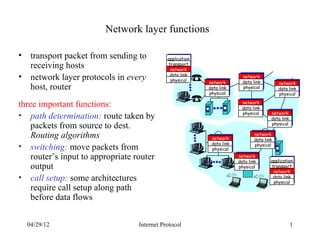
- 1. Network layer functions • transport packet from sending to application receiving hosts transport network • network layer protocols in every data link physical network data link network network host, router data link physical data link physical physical three important functions: network data link physical network • path determination: route taken by data link packets from source to dest. physical Routing algorithms network network data link data link • switching: move packets from physical physical router’s input to appropriate router network data link application output physical transport network • call setup: some architectures data link physical require call setup along path before data flows 04/29/12 Internet Protocol 1
- 2. Network service model Q: What service model for “channel” transporting The most important packets from sender to abstraction provided receiver? by network layer: ? ? • guaranteed bandwidth? • preservation of inter-packet virtual circuit service abstraction timing (no jitter)? or ? • loss-free delivery? datagram? • in-order delivery? • congestion feedback to sender? 04/29/12 Internet Protocol 2
- 3. Virtual circuits “source-to-destination path behaves much like telephone circuit” – performance-wise – network actions along source-to-destination path • call setup, teardown for each call before data can flow • each packet carries VC identifier (not destination host OD) • every router on source-destination path maintain “state” for each passing connection – transport-layer connection only involved two end systems • link, router resources (bandwidth, buffers) may be allocated to VC – to get circuit-like performance. 04/29/12 Internet Protocol 3
- 4. Datagram networks: the Internet model • no call setup at network layer • routers: no state about end-to-end connections – no network-level concept of “connection” • packets typically routed using destination host ID – packets between same source-dest pair may take different paths application application transport transport network data link 1. Send data 2. Receive data network data link physical physical 04/29/12 Internet Protocol 4
- 5. Virtual circuits: signaling protocols • used to setup, maintain teardown VC • used in ATM, frame-relay, X.25 • not used in today’s Internet application 6. Receive data application transport 5. Data flow begins network 4. Call connected 3. Accept call transport data link 1. Initiate call 2. incoming call network data link physical physical 04/29/12 Internet Protocol 5
- 6. Datagram or VC network: why? Internet ATM • data exchange among computers • evolved from telephony – “elastic” service, no strict • human conversation: timing req. – strict timing, reliability • “smart” end systems (computers) requirements – can adapt, perform control, – need for guaranteed service error recovery – simple inside network, • “dumb” end systems complexity at “edge” – telephones • many link types – complexity inside network – different characteristics – uniform service difficult 04/29/12 Internet Protocol 6
- 7. Routing Routing protocol Goal: determine “good” path 5 (sequence of routers) thru 3 network from source to dest. B C 5 2 A 2 1 F 3 Graph abstraction for routing 1 2 algorithms: D E 1 • graph nodes are routers • graph edges are physical • “good” path: links – typically means minimum – link cost: delay, $ cost, or cost path congestion level – other def’s possible 04/29/12 Internet Protocol 7
- 8. Routing Algorithms • There are certain properties that are desirable in a routing algorithm: – correctness – simplicity – robustness – stability – fairness – optimality 04/29/12 Internet Protocol 8
- 9. Routing Algorithm classification Global or decentralized Static or dynamic? information? Static: Global: • routes change slowly over time • all routers have complete Dynamic: topology, link cost info • routes change more quickly • “link state” algorithms – periodic update Decentralized: – in response to link cost • router knows physically- changes connected neighbors, link costs to neighbors • iterative process of computation, exchange of info with neighbors • “distance vector” algorithms 04/29/12 Internet Protocol 9
- 10. A Link-State Routing Algorithm Notation: Dijkstra’s algorithm • c(i,j): link cost from node i to • net topology, link costs known j. cost infinite if not direct to all nodes neighbors – accomplished via “link state • D(v): current value of cost of broadcast” path from source to dest. V – all nodes have same info • p(v): predecessor node along • computes least cost paths from one node (‘source”) to all other path from source to v, that is nodes next v – gives routing table for that • N: set of nodes whose least node cost path definitively known • iterative: after k iterations, know least cost path to k dest.’s 04/29/12 Internet Protocol 10
- 11. Dijsktra’s Algorithm 1 Initialization: 2 N = {A} 3 for all nodes v 4 if v adjacent to A 5 then D(v) = c(A,v) 6 else D(v) = infty 7 8 Loop 9 find w not in N such that D(w) is a minimum 10 add w to N 11 update D(v) for all v adjacent to w and not in N: 12 D(v) = min( D(v), D(w) + c(w,v) ) 13 /* new cost to v is either old cost to v or known 14 shortest path cost to w plus cost from w to v */ 15 until all nodes in N 04/29/12 Internet Protocol 11
- 12. Example 04/29/12 Internet Protocol 12
- 13. Flooding • Every incoming packet is sent out on every outgoing line except the one it arrived on • This algorithm generates vast numbers of duplicate packets but – it will always find the optimal path – it is very robust • Some technique has to be used from generating an infinite number of packets 04/29/12 Internet Protocol 13
- 14. Selective Flooding • A simple variation to the flooding algorithm is to only send outgoing packets in the correct direction • Flooding, in any form, is usually not practical • It is useful in some cases – military applications – distributed database updates – can be used to generate a metric against which other routing algorithms can be compared 04/29/12 Internet Protocol 14
- 15. Distance Vector Routing • Distance vector routing algorithms operate by having each router maintain a table giving the best known distance to each destination and which line to use to get there • The routing decision is simple – find the entry for the destination and send the packet out on the indicated line • The tricky part is building, and maintaining, the tables 04/29/12 Internet Protocol 15
- 16. Table Maintenance • Each router is assumed to know – who its neighbors are – the cost to reach each neighbor • At regular intervals each router sends its routing table to each of its neighbors • When a table is received, a router – steps through the table and computes the cost to each destination – the new route is used if the cost is less 04/29/12 Internet Protocol 16
- 17. Distance Vector Routing: overview Iterative, asynchronous: each Each node: local iteration caused by: • local link cost change • message from neighbor: its wait for (change in local link least cost path change from cost of message from neighbor neighbor) Distributed: recompute distance table • each node notifies neighbors only when its least cost path to any destination changes if least cost path to any – neighbors then notify their destination has changed, neighbors if necessary notify neighbors 04/29/12 Internet Protocol 17
- 18. Example A B 10 Destination Metric Line A 0 - 10 B 10 B 20 C 30 D D 20 D C 10 D Routing Table for A 04/29/12 Internet Protocol 18
- 19. Example Destination Metric Line A 0 - A B B 10 B 10 C 30 D D 20 D 5 20 Routing Table for A Destination Metric Line 10 C D A 10 A B 0 - C 15 D D 5 D Routing Table for B 04/29/12 Internet Protocol 19
- 20. Slow Convergence • Distance Vector Routing works in theory but as a serious drawback in practice – it converges to the correct answer, but it may take a long time to get there A B C D E ∞ ∞ ∞ ∞ 1 ∞ ∞ ∞ 1 2 ∞ ∞ 1 2 3 ∞ 1 2 3 4 04/29/12 Internet Protocol 20
- 21. Count to Infinity • All lines up, and then line between A and B goes down A B C D E 1 2 3 4 Initial 3 2 3 4 AB link down, B decides to route through C 3 4 3 4 C realizes neighbors cost to A is 3 5 4 5 4 5 6 5 6 7 6 7 6 7 8 7 8 … … … … ∞ ∞ ∞ ∞ 04/29/12 Internet Protocol 21
- 22. Split Horizon Hack • Many solutions to the count to infinity problem have been proposed • The split horizon algorithm works the same way as distance vector routing, except that the distance to X is not reported on the line that packets for X are sent on • Split horizon, although widely used, sometimes fails 04/29/12 Internet Protocol 22
- 23. Comparison of LS and DV algorithms Message complexity Robustness: what happens if • LS: with n nodes, E links, O(nE) router malfunctions? msgs sent each LS: • DV: exchange between neighbors – node can advertise incorrect only link cost – convergence time varies – each node computes only its Speed of Convergence own table • LS: O(n**2) algorithm requires DV: O(nE) msgs – DV node can advertise – may have oscillations incorrect path cost • DV: convergence time varies – each node’s table used by – may be routing loops others • error propagate thru network – count-to-infinity problem 04/29/12 Internet Protocol 23
- 24. Hierarchical Routing Our routing study thus far - idealization • all routers identical • network “flat” … not true in practice administrative autonomy scale: with 50 million • internet = network of networks destinations: • each network admin may want to • can’t store all dest’s in routing control routing in its own network tables! • routing table exchange would swamp links! 04/29/12 Internet Protocol 24
- 25. Hierarchical Routing • aggregate routers into gateway routers regions, “autonomous • special routers in AS systems” (AS) • run inter-AS routing • routers in same AS run protocol with all other routers in AS same routing protocol • also responsible for routing – “inter-AS” routing protocol to destinations outside AS – routers in different AS can – run intra-AS routing run different inter-AS protocol with other routing protocol gateway routers 04/29/12 Internet Protocol 25
- 26. Intra-AS and Inter-AS routing C.b Gateways: B.a •perform inter-AS A.a routing amongst b A.c c themselves a C a b •perform intra-AS a B routers with other d c routers in their A b AS network layer inter-AS, intra-AS link layer routing in gateway A.c physical layer 04/29/12 Internet Protocol 26
- 27. Intra-AS and Inter-AS routing Inter-AS C.b routing between B.a A.a A and B Host b A.c c h2 a C a b a B Host d c Intra-AS routing h1 b A within AS B Intra-AS routing within AS A • We’ll examine specific inter-AS and intra-AS Internet routing protocols shortly 04/29/12 Internet Protocol 27
- 28. The Internet Network layer Host, router network layer functions: Transport layer: TCP, UDP Routing protocols IP protocol •path selection •addressing conventions •RIP, OSPF, BGP •datagram format Network •packet handling conventions layer routing table ICMP protocol •error reporting •router “signaling” Link layer physical layer 04/29/12 Internet Protocol 28
- 29. IP: Internet Protocol • IP is the workhorse protocol of the TCP/IP protocol suite • IP provides an unreliable, connectionless, datagram delivery service • The internet protocol implements two basic functions: addressing and fragmentation. • RFC791 is the official specification of IP 04/29/12 Internet Protocol 29
- 30. The Workhorse User User User User application Process Process Process Process TCP UDP transport ICMP IP IGMP network Hardware link ARP RARP Interface 04/29/12 Internet Protocol 30
- 31. IP Header 8 16 31 Version Hdr Len Type of Service Total Length (in bytes) Identification Flags Fragment offset 20 bytes Time to Live Protocol Checksum Source IP Address Destination IP Address options (if any) data 04/29/12 Internet Protocol 31
- 32. Network Byte Ordering • Multi-byte numbers can be stored in one of two ways: – 6000010 = 00000000 00000000 11101010 01100000 Address Big Endian Little Endian Addr0 00000000 01100000 Addr1 00000000 11101010 Addr2 11101010 00000000 Addr3 01100000 00000000 • Network byte order is big endian 04/29/12 Internet Protocol 32
- 33. IP Header Fields Field Description Version The Version field indicates the format of the internet header. The current protocol version is 4 (sometimes called IPv4) Header Length The length of the header in 32-bit words. Note that the minimum value for a correct header is 5. Total Length The total length of the IP datagram in bytes (data and header) Time to Live Sets an upper limit on the number of routers through which a datagram can pass. It is initialized by the sender (often 32 or 64) and decremented by one each time the packet passes through a router. When it reaches 0, the packet is discarded 04/29/12 Internet Protocol 33
- 34. Type of Service • The IP protocol provides a (rather limited) facility for upper layer protocols to convey hints to the Internet Layer about how the tradeoffs should be made for the particular packet 3-bit 4-bit MBZ precedence TOS 04/29/12 Internet Protocol 34
- 35. TOS Field Values • There are 4 defined values for the TOS field Value Meaning 1000 Minimize delay 0100 Maximize throughput 0010 Maximize reliability 0001 Minimize monetary cost 0000 Normal service (default) • Note these values are defined as integers, not as bits 04/29/12 Internet Protocol 35
- 36. Recommended TOS Values Application Minimize Maximize Maximize Minimize Hex Value Delay Throughput Reliability Monetary Cost Telnet/Rlogin 1 0 0 0 0x10 FTP Control 1 0 0 0 0x10 Bulk 0 1 0 0 0x08 TFTP 1 0 0 0 0x10 SMTP Command 1 0 0 0 0x10 Data 0 1 0 0 0x08 DNS UDP query 1 0 0 0 0x10 TCP query 0 0 0 0 0x00 Transfer 0 1 0 0 0x08 ICMP Error 0 0 0 0 0x00 Query 0 0 0 0 0x00 SMNP 0 0 1 0 0x02 BOOTP 0 0 0 0 0x00 NNTP 0 0 0 1 0x01 04/29/12 Internet Protocol 36
- 37. Fragmentation • The physical layer often imposes an upper limit on the size of the frame that can be transmitted • IP compares the MTU with the datagram size and performs fragmentation, if necessary • Fragmentation can take place at the original host or at an intermediate router • IP datagrams are not reassembled until they reach their final destination 04/29/12 Internet Protocol 37
- 38. Fragmentation and the Header • The following fields are used in fragmentation – identification • contains a unique value for each IP datagram that the sender transmits – flags Don’t More MBZ fragment fragments – fragment offset • the offset of the fragment from the beginning of the original datagram 04/29/12 Internet Protocol 38
- 39. Fragmentation • If fragmentation must occur… – if the “don’t fragment” bit is turned on the packet is discarded – the packet is split into fragments • the header is basically copied except for… – total length is changed to the size of the fragment – the fragmentation offset is set to the the offset of the fragment from the beginning of the original datagram – the “more fragments” bit is turned on in every fragment except for the last one 04/29/12 Internet Protocol 39
- 40. Reassembly • The identification field is used to ensure that fragments of different datagrams are not mixed. • The fragment offset field tells the receiver the position of a fragment in the original datagram • The fragment offset and length determine the portion of the original datagram covered by this fragment • The more-fragments flag indicates (by being reset) the last fragment 04/29/12 Internet Protocol 40
- 41. Protocol Field • This field indicates the next level protocol used in the data portion of the internet datagram • The values for various protocols are specified in RFC1060 (Assigned Numbers) Number Protocol 0 Reserved 1 ICMP 2 IGMP 6 TCP 17 UDP 04/29/12 Internet Protocol 41
- 42. Header Checksum • The header checksum is calculated over the IP header only • The checksum is calculated as follows: – set the checksum field to 0 – calculate the 16-bit one’s complement sum of the header – the 16-bit one’s complement of this sum is stored in the checksum field 04/29/12 Internet Protocol 42
- 43. Header Checksum • When an IP datagram is received, the 16-bit one’s complement sum of the header is calculated • Since the receiver’s calculated checksum contains the checksum stored by the sender, the calculated result should be all ones • If the checksum is wrong, the packet is quietly discarded. No error messages are generated • ICMP, IGMP, UDP, and TCP all use the same checksum 04/29/12 Internet Protocol 43
- 44. Addressing • A distinction is made between names, addresses, and routes – A name indicates what we seek – An address indicates where it is – A route indicates how to get there • The internet protocol deals primarily with addresses. It is the task of higher level protocols to make the mapping from names to addresses. 04/29/12 Internet Protocol 44
- 45. IP Addresses • Every interface on the internet must have a unique Internet Address (also called an IP address) • IP addresses are 32-bits numbers • The addresses are not flat, they are divided into two components: the host address and the network address • The number of bits assigned to the host portion and network portion of the address varies depending on the class of the address 04/29/12 Internet Protocol 45
- 46. IP Address Classes 7 bits 24 bits Class A 0 netid hostid 14 bits 16 bits Class B 1 0 netid hostid 21 bits 8 bits Class C 1 1 0 netid hostid 28 bits Class D 1 1 1 0 multicast group ID 27 bits Class E 1 1 1 1 0 (reserved for future use) 04/29/12 Internet Protocol 46
- 47. Dotted Decimal Notation • IP addresses are normally written as four decimal numbers, one for each byte of the address. – 129.21.38.169 • The easiest way to differentiate between the classes is to look at the first number Class Range A 0.0.0.0 to 127.255.255.255 B 128.0.0.0 to 191.255.255.255 C 192.0.0.0 to 223.255.255.255 D 224.0.0.0 to 239.255.255.255 E 240.0.0.0 to 247.255.255.255 04/29/12 Internet Protocol 47
- 48. Assigning IP Addresses • Since every interface must have a unique IP address, there must be a central authority for assigning numbers • That authority is the Internet Network Information Center, called the InterNIC. • The InterNIC assigns only network ids, the assignment of host ids is up to the system administrator 04/29/12 Internet Protocol 48
- 49. Subnet Addressing • The original view of the Internet universe was a two-level hierarchy: – the top level the Internet as a whole – the level below it individual networks, each with its own network number. • In this two-level model, each host sees its network as a single entity 04/29/12 Internet Protocol 49
- 50. Subnet Addressing • While the two-level view has proved simple and powerful, a number of organizations have found it inadequate, and have added a third level to the interpretation of Internet addresses. • In this view, a given Internet network is divided into a collection of subnets. • The three-level model is useful in networks belonging to moderately large organizations 04/29/12 Internet Protocol 50
- 51. Subnet Addressing • Locally IP addresses consist of three parts: – network ID – subnet ID – host ID • Outside of the subnetted network the addresses are handled normally • Inside the subnet, the network portion of the address is extended for local routing purpose 04/29/12 Internet Protocol 51
- 52. Subnet Masks • Once the decision to subnet has been made, the local administrator must decide how many bits to allocate to the subnet ID • A common division is to use the 8-bit boundary in the 16 bits of a host ID in a class B address • A subnet mask is used to divide the local address into network and host portions • Subnetting effectively hides the details of the internal network to external routers 04/29/12 Internet Protocol 52
- 53. Special IP Addresses IP Address Can Appear as Description Net ID Subnet ID Host ID Source? Destination? 0 0 OK Never This host on this net 0 hostid OK Never Specified host on this net 127 anything OK OK Loopback address 255 255 Never OK Limited broadcast (never forwarded) netid 255 Never OK Net-directed broadcast to netid netid Subnetid 255 Never OK Subnet-direct broadcast to netid, subnetid netid 255 255 Never OK All-subnets-directed broadcast to netid 04/29/12 Internet Protocol 53
- 54. IP Options Field • The options field is a variable-length list of optional information for the datagram • The options currently defined are – security and handling restrictions (RFC1108) – record route – timestamp – loose & strict source routing • The options field always ends on a 32-bit boundary 04/29/12 Internet Protocol 54
- 55. IP Routing • Routing is one of the most important functions of IP • Datagrams to be routed can either be generated on the local host or on some other host • If a machine is not configured as a router, datagrams received through network interfaces that are not addressed to the machine are dropped 04/29/12 Internet Protocol 55
- 56. Host Routing • Conceptually IP routing is easy, especially for a host – Remember the structure of an internet address • If the destination is directly connected to the host, or on a shared network, then the datagram is sent directly • Otherwise the host sends the datagram to a default router, and lets the router do all of the work 04/29/12 Internet Protocol 56
- 57. IP routing Algorithm • The basic internet routing algorithm is used by both hosts and routers • The primary difference is that hosts never forward datagrams (except to a default router), whereas routers forward datagrams • The algorithm uses a routing table to make routing decisions 04/29/12 Internet Protocol 57
- 58. A Typical Routing Table • Each entry in the routing table contains the following information – Destination IP address. • this can be either a host address or a network address – IP address of the next-hop router, or the IP address of a directly connected network – Flags that tell more about the entry – Which interface the datagram should be passed to for delivery 04/29/12 Internet Protocol 58
- 59. IP routing • IP routing performs the following actions – search the routing table for an entry that matches the complete destination address. If found, send the packet as indicated – search the routing table for a matching destination network ID. If found, send the packet as indicated – search the routing table for a default entry. If found send the packet as indicated • If none of the steps work, the datagram is undeliverable 04/29/12 Internet Protocol 59
- 60. IP Layer Routing 04/29/12 Internet Protocol 60
- 61. IP Routing • The routing done by IP, when it searches the routing table and decides which interface to send a packet out, is a routing mechanism • A routing policy is a set of rules that determines which routes go into the routing table. • IP performs the routing mechanism while a routing daemon normally provides the routing policy. 04/29/12 Internet Protocol 61
- 62. Initializing a Routing Table • One common way is to execute the route command explicitly from the initialization files when the system is being bootstrapped. • Some systems allow a default router to be specified in a file such, and this default is added to the routing table on every reboot. • Other ways to initialize a routing table are to run a routing daemon or to use the newer router discovery protocol. 04/29/12 Internet Protocol 62
- 63. Routing Errors • What happens if there is no default route, and a match is not found for a given destination? • If the datagram was generated locally, an error is returned to the application that sent the datagram (either “host unreachable” or “network unreachable”) • What do I do if I am a router? – Sender should be notified of the error 04/29/12 Internet Protocol 63
- 64. Internet Control Message Protocol • ICMP communicates error messages and other conditions that require attention • ICMP is often considered part of the IP layer • RFC792 is the official specification for ICMP • ICMP messages are transmitted within IP datagrams 04/29/12 Internet Protocol 64
- 65. ICMP Packet Format • The first 4 bytes of the same format for all messages, the remainder differs from one message to the next 8-bit type 8-bit code 16-bit checksum contents depend on type and code 04/29/12 Internet Protocol 65
- 66. ICMP Message Types Type Code Description Query Error 0 0 Echo reply • 3 Destination unreachable: 0 Network unreachable • 1 Host unreachable • 2 Protocol unreachable • 3 Port unreachable • 4 Fragmentation needed • 5 Source route failed • 6 Destination network unknown • 7 Destination host unknown • 8 Source host isolated 9 Destination net prohibited • 10 Destination host prohibited • 11 Network unreachable for TOS • 12 Host unreachable for TOS • 13 Communication prohibited • 14 Host precedence violation • 15 Precedence cutoff in effect • 4 0 Source quench • 04/29/12 Internet Protocol 66
- 67. ICMP Message Types Type Code Description Query Error 5 Redirect 0 Redirect for network • 1 Redirect for host • 2 Redirect for TOS and Net • 3 Redirect for TOS and Host • 8 0 Echo request • 9 0 Router advertisement • 10 0 Router solicitation • 11 Time exceeded 0 TTL equals 0 during transit • 1 TTL equals 0 during reassembly • 12 Parameter problem 0 IP header bad • 1 Required option missing • 13 0 Timestamp request • 14 0 Timestamp reply • 15 0 Information request • 16 0 Information reply • 17 0 Address mask request • 18 0 Address mask reply • 04/29/12 Internet Protocol 67
- 68. ICMP Error Messages • When an ICMP error message is sent, the message always contains the IP header and the first 8 bytes of the IP datagram that caused the problem • ICMP has rules regarding error message generation to prevent broadcast storms 04/29/12 Internet Protocol 68
- 69. Error Message Generation Rules • ICMP errors messages are not generated in response to – an ICMP error message – datagrams destined to an IP broadcast address – datagrams sent as a link-layer broadcast – a fragment other than the first – a datagram whose source address does not define a single host 04/29/12 Internet Protocol 69
- 70. ICMP Timestamp Request & Reply • This option allows a system to query another for the current time. • The recommended value to be returned is the number of milliseconds since midnight, Coordinated Universal Time (UTC). • A drawback is that only the time since midnight is returned. The caller must know the date form some other means 04/29/12 Internet Protocol 70
- 71. Timestamp Message Format type (13 or 14) code (0) 16-bit checksum identifier (can be set to anything) sequence (can be set to anything) 32-bit originate timestamp 32-bit receive timestamp 32-bit transmit timestamp 04/29/12 Internet Protocol 71
- 72. Time Adjustments • The time fields are defined as follows – originate: time the request is sent – receive: time the request is received by the receiver – transmit: time the reply is sent originate received request reply transmit RTT • Adjustment: (recv - orig) - (0.5 * RTT) 04/29/12 Internet Protocol 72
- 73. ICMP Unreachable Error • Unreachable errors are generate for a number of reasons – network unreachable – host unreachable type (3) code (0-15) 16-bit checksum unused (must be 0) IP header (including options) + first 8 bytes of IP datagram data 04/29/12 Internet Protocol 73
- 74. Handling of ICMP Messages Type Code Description Handled by 0 0 Echo reply User process 3 Destination unreachable: 0 Network unreachable “No route to host” 1 Host unreachable “No route to host” 2 Protocol unreachable “Connection refused” 3 Port unreachable “Connection refused” 4 Fragmentation needed “Message too long” 5 Source route failed “No route to host” 6 Destination network unknown “Network is unreachable” 7 Destination host unknown “No route to host” 8 Source host isolated “No route to host” 9 Destination net prohibited “Network is unreachable” 10 Destination host prohibited “No route to host” 11 Network unreachable for TOS “Network is unreachable” 12 Host unreachable for TOS “No route to host” 13 Communication prohibited (ignored) 14 Host precedence violation (ignored) 15 Precedence cutoff in effect (ignored) 4 0 Source quench Kernel for TCP; ignored by UDP 04/29/12 Internet Protocol 74
- 75. Handling of ICMP Messages Type Code Description Handled by 5 Redirect 0 Redirect for network Kernel updates routing table 1 Redirect for host Kernel updates routing table 2 Redirect for TOS and Net Kernel updates routing table 3 Redirect for TOS and Host Kernel updates routing table 8 0 Echo request Kernel generates reply 9 0 Router advertisement User process 10 0 Router solicitation User process 11 Time exceeded 0 TTL equals 0 during transit User process 1 TTL equals 0 during reassembly User process 12 Parameter problem 0 IP header bad “Protocol not available” 1 Required option missing “Protocol not available” 13 0 Timestamp request Kernel generates reply 14 0 Timestamp reply User process 15 0 Information request Kernel generates reply 16 0 Information reply User process 17 0 Address mask request Kernel generates reply 18 0 Address mask reply User process 04/29/12 Internet Protocol 75
- 76. ICMP Redirect Errors • The ICMP redirect error is sent by a router to a sender of an IP datagram when the datagram should have been sent to a different router. 04/29/12 Internet Protocol 76
- 77. Sending a Redirect • How can a router make this decision? – Assume a host sends an IP datagram to R1. This routing decision is often made because R1 is the default router – R1 receives the datagram and determines that R2 is the next-hop router – When it sends the datagram to R2, R1 detects that it is sending it out the same interface on which the datagram arrived. – R1 sends an ICMP redirect to the host, telling it to send 04/29/12 future datagrams to Internetdestination to R2 that Protocol 77
- 78. Using Redirects • A common use for redirects is to let a host with minimal routing knowledge build up a better routing table over time. • The host can start with a default route and anytime this turns out to be wrong, it will be informed by that router with a redirect, allowing the host to update its routing tables accordingly. 04/29/12 Internet Protocol 78
- 79. Redirect Rules • There are rules regarding the generation of ICMP redirects. – Redirects are generated only by routers, and not by hosts – Redirects are intended to be used by hosts, not by routers (it is assumed that routers participate in a routing protocol with other routers, and the routing protocol eliminates the needs for redirects) 04/29/12 Internet Protocol 79
- 80. Handling Redirects • A host that receives an ICMP redirect performs some checks before modifying its routing table – the new router must be on a directly connected network – the redirect must be from the current router for that destination – the redirect cannot tell the host to use itself as the router – the route that is being modified must be a direct route • Routers should send only host redirects and not network redirects 04/29/12 Internet Protocol 80
- 81. ICMP Router Discovery • A newer way to initialize a routing table is to use the ICMP router advertisement and solicitation • The general concept is that after bootstrapping, a host broadcasts or multicasts a router solicitation message. One or more routers respond with a router advertisement message • Routers periodically broadcast or multicast their router advertisements • RFC1256 specifies the format of these messages 04/29/12 Internet Protocol 81
- 82. Message Formats 04/29/12 Internet Protocol 82
- 83. Router Discovery Messages • Multiple addresses can be advertised by a router in a single message – number of addresses gives the number of addresses in the message – address entry size is the number of 32-bit words for each router address and is always 2 – lifetime is the number of seconds that the advertised addresses can be considered valid 04/29/12 Internet Protocol 83
- 84. Router Discovery Messages • Pair(s) of IP addresses and a preference then follow (the address must be router's IP address) • The preference level indicates the preference of this address as a default router – Larger values imply more preferable addresses. – The preference level 0x80000000 indicates that the corresponding address, although advertised, should not be used by the receiver as a default router address – The default value is normally 0. 04/29/12 Internet Protocol 84
- 85. Router Discovery Operation • When a router starts up it transmits periodic advertisements on all interfaces capable of broadcasting or multicasting • The default lifetime for a given advertisement is 30 minutes. • The lifetime field is is also used when an interface on a router is disabled. In this case the router transmits an advertisement with lifetime set to 0. 04/29/12 Internet Protocol 85
- 86. Router Discovery Operation • A router also listens for solicitations from hosts. It responds to these solicitations with a router advertisement. • If there are multiple routers on a subnet, it is up to the system administrator to configure the preference level for each router as appropriate. For example a primary router would have a higher preference than a backup. 04/29/12 Internet Protocol 86
- 87. Host Discovery Operation • Upon bootstrap a host normally transmits three router solicitations, 3 seconds apart • A host listens for advertisements from adjacent routers. These advertisements can cause the host's default router to change • If an advertisement is not received for the current default, that default can timeout – A router will send advertisements every 10 minutes, with a lifetime of 30 minutes 04/29/12 Internet Protocol 87
- 88. CS Network 129.21.38.254 129.21.37.254 129.21.39.254 129.21.30.254 mordor-38 mordor-37 mordor-39 mordor 129.21.38.218 129.21.37.218 129.21.39.218 129.21.30.26 kiev silver 129.21.38.145 129.21.37.175 staff ICL2 ICL1 servers ICL3 ICL4 CSL Grad Lab 04/29/12 Internet Protocol 88
- 89. Kiev ifconfig kiev> ifconfig -a lo0: flags=849<UP,LOOPBACK,RUNNING,MULTICAST> mtu 8232 inet 127.0.0.1 netmask ff000000 hme0: flags=863<UP,BROADCAST,NOTRAILERS,RUNNING,MULTICAST> mtu 1500 inet 129.21.38.145 netmask ffffff80 broadcast 129.21.38.255 kiev> 04/29/12 Internet Protocol 89
- 90. Mordor ifconfig mordor> ifconfig -a lo0: flags=849<UP,LOOPBACK,RUNNING,MULTICAST> mtu 8232 inet 127.0.0.1 netmask ff000000 hme0: flags=863<UP,BROADCAST,NOTRAILERS,RUNNING,MULTICAST> mtu 1500 inet 129.21.30.26 netmask ffffff80 broadcast 129.21.30.127 qfe0: flags=863<UP,BROADCAST,NOTRAILERS,RUNNING,MULTICAST> mtu 1500 inet 129.21.37.218 netmask ffffff80 broadcast 129.21.37.255 qfe1: flags=863<UP,BROADCAST,NOTRAILERS,RUNNING,MULTICAST> mtu 1500 inet 129.21.38.218 netmask ffffff80 broadcast 129.21.38.255 qfe2: flags=863<UP,BROADCAST,NOTRAILERS,RUNNING,MULTICAST> mtu 1500 inet 129.21.39.218 netmask ffffff80 broadcast 129.21.39.255 mordor> 04/29/12 Internet Protocol 90
- 91. Grace ifconfig $ ifconfig -a tu0: flags=c63<UP,BROADCAST,NOTRAILERS,RUNNING,MULTICAST,SIMPLEX> fta0: flags=8c63<UP,BROADCAST,NOTRAILERS,RUNNING,MULTICAST,SIMPLEX> inet 129.21.3.102 netmask ffffff00 broadcast 129.21.3.255 ipmtu 4352 sl0: flags=10<POINTOPOINT> lo0: flags=100c89<UP,LOOPBACK,NOARP,MULTICAST,SIMPLEX,NOCHECKSUM> inet 127.0.0.1 netmask ff000000 ipmtu 4096 04/29/12 Internet Protocol 91
- 92. Kiev netstat kiev> netstat -rn Routing Table: Destination Gateway Flags Ref Use Interface -------------------- -------------------- ----- ----- ------ --------- 129.21.38.128 129.21.38.145 U 3 3056 hme0 224.0.0.0 129.21.38.145 U 3 0 hme0 default 129.21.38.254 UG 0 21129 127.0.0.1 127.0.0.1 UH 0 21718 lo0 kiev> 04/29/12 Internet Protocol 92
- 93. Mordor netstat mordor> netstat -rn Routing Table: Destination Gateway Flags Ref Use Interface -------------------- -------------------- ----- ----- ------ --------- 129.21.30.0 129.21.30.26 U 3 374 hme0 129.21.37.128 129.21.37.218 U 2 2667 qfe0 129.21.38.128 129.21.38.218 U 2 2858 qfe1 129.21.39.128 129.21.39.218 U 2 1967 qfe2 224.0.0.0 129.21.30.26 U 3 0 hme0 default 129.21.30.126 UG 0 4762 127.0.0.1 127.0.0.1 UH 08072949 lo0 mordor> 04/29/12 Internet Protocol 93
- 94. traceroute kiev> traceroute silver traceroute: Warning: ckecksums disabled traceroute to silver (129.21.37.175), 30 hops max, 40 byte packets 1 cs3-router (129.21.38.254) 0.716 ms 0.513 ms 0.523 ms 2 silver (129.21.37.175) 1.703 ms * 0.988 ms kiev> traceroute mordor traceroute: Warning: ckecksums disabled traceroute to mordor (129.21.30.26), 30 hops max, 40 byte packets 1 cs3-router (129.21.38.254) 0.635 ms 0.496 ms 0.527 ms 2 mordor-38 (129.21.38.218) 0.590 ms * 0.746 ms kiev> traceroute mordor-38 traceroute: Warning: ckecksums disabled traceroute to mordor-38 (129.21.38.218), 30 hops max, 40 byte packets 1 mordor-38 (129.21.38.218) 0.558 ms * 0.457 ms kiev> 04/29/12 Internet Protocol 94
- 95. traceroute kiev> traceroute grace traceroute: Warning: ckecksums disabled traceroute to grace.rit.edu (129.21.3.102), 30 hops max, 40 byte packets 1 cs3-router (129.21.38.254) 0.730 ms 0.572 ms 0.442 ms 2 grace.isc.rit.edu (129.21.3.102) 0.794 ms 0.724 ms 0.697 ms kiev> $ traceroute kiev.cs.rit.edu traceroute to kiev.cs.rit.edu (129.21.38.145), 30 hops max, 40 byte packets 1 r33.isc.rit.edu (129.21.3.217) 1 ms 1 ms 0 ms 2 kiev.cs.rit.edu (129.21.38.145) 1 ms * 1 ms $ 04/29/12 Internet Protocol 95
- 96. PTT-net • Recently got Road Runner • Unhappy about reports of constant probes of machines • Policy decision – I want to prevent unauthorized probes/connection attempts on my machines • Mechanism – Purchase some sort of firewall for my home network 04/29/12 Internet Protocol 96
- 97. DI-701 Manufacturer: D-Link (www.dlink.com) 04/29/12 Internet Protocol 97
- 98. Configuration Desktop Internet Cable Modem DI-701 Hub Laptop Printer 04/29/12 Internet Protocol 98
- 99. Address Management RR-DHCP (24.93.24.121) Desktop Internet Cable Modem DI-701 Hub Laptop DLINK (192.168.0.1) Printer DLINK-DHCP (192.168.0.2 – 192.168.0.32) 04/29/12 Internet Protocol 99
- 100. Firewall Internet traffic stops here Desktop Internet Cable Modem DI-701 Hub Laptop Filters Internet traffic… Printer Addresses never go past firewall 04/29/12 Internet Protocol 100
- 101. BCP-5 • The Internet has grown beyond anyone's expectations. Sustained exponential growth… • One challenge is that globally unique address space will be exhausted. • A separate and far more pressing concern is that the amount of routing overhead will grow beyond the capabilities of Internet Service Providers. • Efforts are in progress to find long term solutions to both of these problems. 04/29/12 Internet Protocol 101
- 102. Types of Hosts • Hosts using IP can be grouped into 3 categories: – Category 1 • Hosts that do not require access to hosts in other enterprises or the Internet at large – Category 2 • Hosts that need access to a limited set of outside services which can be handled by mediating gateways. For many hosts in this category an unrestricted external access may be unnecessary and even undesirable for security reasons. – Category 3: • Hosts that need network layer access outside the enterprise (provided via IP connectivity) 04/29/12 Internet Protocol 102
- 103. Ramifications • Hosts using IP can be grouped into 3 categories: – Category 1 • IP addresses need to be unambiguous within an enterprise, but may be ambiguous between enterprises. – Category 2 • Just like hosts within the first category, hosts may use IP addresses that are unambiguous within an enterprise, but may be ambiguous between enterprises. – Category 3: • Requires IP addresses that are globally unambiguous. 04/29/12 Internet Protocol 103
- 104. PTT-net • PTT-net clearly falls into category 1 or 2 – Assuming the DI-701 is doing its job • The Internet Assigned Numbers Authority (IANA) has reserved the following three blocks of the IP address space for private internets: – 10.0.0.0 - 10.255.255.255 – 172.16.0.0 - 172.31.255.255 – 192.168.0.0 - 192.168.255.255 04/29/12 Internet Protocol 104
- 105. Mystery • PTT’s laptop opens a TCP connection to the CS department’s web server – Laptop’s address is 192.168.0.2:1234 – Destination is 129.21.30.29:80 – Routed to DI-701 – DI-701 replaces with address with 24.93.24.121 – RIT responds, destination 24.93.24.121 – Arrives at DI-701 – How does the DI-702 know the send the packet to the laptop? 04/29/12 Internet Protocol 105
- 106. Mystery Solved Private Address Private Port External External Port NAT Protocol Address Port Used 192.168.0.2 1234 129.21.30.21 80 14003 TCP 192.1.68.0.1 386 129.2.1.30.21 80 14004 TCP 192.168.0.2 5000 129.21.30.24 25 14005 TCP 192.168.0.1 5000 129.21.30.24 25 14006 TCP 04/29/12 Internet Protocol 106
- 107. Network Address Translator • NAT is a method by which IP addresses are mapped from one realm to another • NAT devices connect an isolated address realm to a realm with globally unique registered addresses • There are a variety of flavors of NAT and terms to match them • RFC-2663 is an attempt to define NAT 04/29/12 Internet Protocol 107
- 108. Common Characteristics • All flavors of NAT devices should share the following characteristics. – Transparent Address assignment. – Transparent routing through address translation. (routing here refers to forwarding packets, and not exchanging routing information) – ICMP error packet payload translation. 04/29/12 Internet Protocol 108
- 109. Basic Idea • NAT devices attempt to provide transparent routing – Source/Destination addresses are modified en-route – The NAT device maintains state so that the datagrams are routed to the correct end-node – This solution works only when the applications do not use the IP addresses as part of the protocol itself 04/29/12 Internet Protocol 109
- 110. Translation • TCP/UDP sessions are uniquely identified by the tuple – (source-IP, source-port, dest-IP, dest-port) • ICMP query sessions are identified by – (source-IP, ICMP query ID, dest-IP) • All other sessions – (source-IP, dest-IP, IP protocol) 04/29/12 Internet Protocol 110
- 111. Start of Session • TCP – The first packet of every sessions contains a SYN bit and no ACK bit – All other TCP packets will have the ACK bit set • UDP – No deterministic way to determine the start of a session – Assume the first packet with never before seen parameters marks the start of a session 04/29/12 Internet Protocol 111
- 112. IP Futures • There are problems with IP which are a result of the phenomenal growth of the Internet over the past few years – as of 1994, over half of the class B addresses have been allocated – 32-bit IP addresses are inadequate – the current routing structure is basically flat, making routing tables too large • CDIR fixes the last problem for a while 04/29/12 Internet Protocol 112
- 113. New IP Versions • Four proposals have been made for a new version of IP – SIP, the Simple Internet Protocol. Proposes a minimal set of changes to IP that uses 64-bit addresses and a different header format – PIP, larger, variable length, hierarchical addresses with a different header format – TUBA (RFC1347), TCP and UDP with bigger addresses – TP/IX (RFC1475), 64-bit addresses, changes TCP/UDP 04/29/12 Internet Protocol 113
- 114. References • The May 1993 issue of IEEE Network (volume 7, number 3) contains overviews of the first three proposals, along with an article on CDIR. • RFC1454 also compares the first three proposals 04/29/12 Internet Protocol 114