

Recommended
More Related Content
What's hot
What's hot (19)
Similar to ES-22-EUT-S213 Manual
Similar to ES-22-EUT-S213 Manual (20)
More from Domotica daVinci
More from Domotica daVinci (20)
Recently uploaded
Recently uploaded (20)
ES-22-EUT-S213 Manual
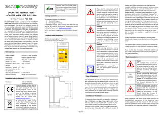
- 1. Strona 1 OPERATING INSTRUCTIONS ADAPTER euFIX S213 & S213NP for Fibaro® module FGS-213 The euFIX S213 Adapter is used to install the Fibaro® Switch FGS-213 module on DIN TH35 type rail in the elec- trical switchboard. The euFIX S213 Adapter consists of the case and the base board, where the FGS-213 module is mounted. The dimensions of the case are appropriate for a standard DIN TH35 type rail. The base board con- tains a set of screw terminals, where all the wires (power supply, input and output signals, control push-buttons) can be safely connected. The front panel of the case con- tains two diagnostics micro-push-buttons S1 & S2, which can be used to control the module, to register the mod- ule within the Z-Wave system or to remove it from the system without opening the adapter's case. The simpli- fied S213NP variation does not have the micro-push-but- tons. Please note that the Fibaro® FGS-213 module is not included and needs to be purchased separately. Technical Data Supply voltage: 230 VAC+/-10%,50–60Hz Load power: max 8 A (resistive load) Dimensions: 34.8 x 87.3 x 64.7 mm Width in TE units: 2 TE modules Conductor wires cross section: max. 2.5 mm2 Maximum length of wires connected to Sx, S1, S2 inputs: 10 m Operating temperature: 0 °C to +50 °C Relative humidity: ≤90 %, no condensation Compliance with EU Directives Directives: LVD 2014/35/EC RoHS 2011/65/EU AB 012 Eutonomy hereby certifies that the said unit is compliant with essen- tial requirements and is in con- formity with other relevant provi- sions of the above directives. The official Declaration of Con- formity can be found here: www.eutonomy.com/ce. At the end of its useful life this product shall not be disposed with other household or municipal waste. Disposing of this product correctly will help save valuable re- sources and prevent any potential negative effects on human health and the environment, which could otherwise arise from inappropriate waste handling. Package Contents The package contains the following: 1. The euFIX Adapter 2. Operating instructions If anything is missing, please contact your seller. You can also call or e-mail us at Eutonomy using contact details that can be found here: www.eutonomy.com. NOTE! The Fibaro® modules are not included in the pack- age. Drawings of kit components All dimensions are given in millimetres. Front view of the euFIX Adapter: Side view of the euFIX Adapter: Considerations and Cautions Please read the instructions carefully prior to installation. The instructions contain important guidelines which, when ignored, can lead to danger to life or health. The manufacturer of the equipment is not responsible for any damages resulting from the use of the product in a manner non-com- pliant with the operating instruc- tions. DANGER Electrocution risk! The equipment is intended for oper- ation in the electrical installation. In- correct wiring or use can result in a fire or an electric shock. All installa- tion works can be performed only by a qualified person holding licenses issued in accordance with regula- tions. DANGER Electrocution risk! Before carrying out any rewiring works on the equipment it is manda- tory to disconnect it from the power mains using a disconnector or a cir- cuit breaker in the electrical circuit. The equipment shall be protected by means of an overcurrent circuit breaker with nominal current of 10 A or less and a minimum contact dis- tance 3 mm. The equipment is intended for in- door use (International Protection Rating IP20). Place of Installation The installation site can be an electrical switchboard or any distribution box, equipped with DIN (TH35) rail. This device is intended for use in all locations where the light or other control circuits coincide in the switchgear and not in the flush-mounted boxes behind the wall switches. Therefore, the wiring should be planned as early as pos- sible, preferably at the stage of the building’s electrical installations and cabling topology design. Installation of the adapter To place the Fibaro module in the adapter, remove the top of the adapter casing, gently prying the side latches. The base plate has a pin header with a number of pins equal to the number of screw terminals of the corre- sponding Fibaro module. The pin spacing prevents acci- dental insertion of a module with a different number of dowels, but Fibaro assortments also have different modules that have the same number of screw terminals. For this reason please pay close attention to the com- patibility of the Fibaro module with your particular adapter version. There is a Fibaro type imprint on the base plate, which is there to help avoid mistakes. The Fibaro module must be pushed against the pins as far as possible and then tightened with the same force as with normal connecting cables. The pin header conducts cur- rent up to 16A, provided that it is properly adhered to the Fibaro screw terminals. The Z-Wave communication antenna can be positioned along the module, so be sure not to get caught while closing the adapter casing. After making sure that all Fibaro screw terminals are securely tightened to the pin header, the casing can be closed and the module and adapter are ready for installation in the switchgear. Proper orientation of the adapter in the switchgear should make it easy to read descriptions on the adapter label. The adapter label contains a white box for marking the module according to your building’s installation design. If you need to take the adapter off the DIN TH35, simply pry a latch at the bottom of the adapter casing with a thin, flat screwdriver. Cable Connections NOTE! The installed device can be con- nected to the power mains only by a person qualified to carry out electrical works, holding licenses issued in accordance with regula- tions. Before commencing any installa- tion works, please make sure that the mains power supply is discon- nected at the distribution board by means of a B10 overcurrent cir- cuit breaker dedicated for the equipment. If there are reasonable grounds to suspect that the equipment is damaged and cannot be operated safely, do not connect it to the power mains and protect it against accidental powering. When connecting the device to the master function, the manufacturer's instructions for the respective Fibaro module supplied with this module are fully developed. Particular attention should be paid to the warnings and limit values of the module as published in the manual. L 1 QS2S1Sx FGS-213 Single Switch 2 NL L euFIX S213 N 10A
- 2. Strona 2 The connections diagram of the adapter is shown below: The descriptions of the screw terminals are printed on the adapter label. The „Q1” letters indicate the relay out- put. The adapter has duplicated L and N power screw termi- nals that are internally connected by bridges that with- stand current much greater than 16A. In case of low load current (for example: a group of electro-valves that con- sume only several watts of power), the modules power supply can be cascaded, solving the problem of safe branching of phase wires. Nevertheless, at any point of the circuit, the load current must not exceed 10 A. Configuration and Commissioning of the Equipment The S1 and S2 micro-buttons on top of the adapter casing can be used for diagnostics and registering of the Fibaro module with the Z-Wave system. In case of the simplified adapter variation without micro-buttons (NP), connect an external button to the screw terminals S1 and S2. The detailed procedure is published in the Fibaro module manual. Maintenance of the Equipment The adapter can be wiped off with a cloth without the use of aggressive detergents. Do not use a wet cloth to clean the appliance. The adapter does not require any additional mainte- nance over time; it is only possible to check the correct- ness of the tightening of the connecting wires during rou- tine switchboard inspections. Do not carry out any repairs inside the unit. All repairs shall be per- formed by a specialist service indi- cated by the manufacturer. Im- properly performed repairs may endanger the safety of users. Service In case of erratic device operation we kindly ask you to inform the manufacturer either via an authorized seller or directly by using e-mail addresses and telephone num- bers available on our website www.eutonomy.com. Apart from the description of the problem please specify the adapter type. Our Service Department will do their best to solve the problem or your device will be admitted for guarantee or post-guarantee repair. Guarantee Terms and Conditions GENERAL PROVISIONS 1. The device is covered with a guarantee. Terms and conditions of the guarantee are outlined in this guaran- tee statement. 2. The guarantor of the Equipment is Eutonomy Sp. z o.o. Sp. Komandytowa based in Łódź (address: ul. Piotrkow- ska 121/3a; 90-430 Łódź, Poland), entered into the Reg- ister of Entrepreneurs of the National Court Register kept by the District Court for Łódź-Śródmieście in Łódź, XX Commercial Division of the National Court Register, un- der no. 0000614778, Tax ID No PL7252129926. 3. The guarantee is valid for a period of 12 months from the date the Equipment was purchased and covers the territory of EU and EFTA countries. 4. This guarantee shall not exclude, limit or suspend the Customer rights resulting for the warranty for defects of the purchased goods. OBLIGATIONS OF THE GUARANTOR 5. During the guarantee period the Guarantor is liable for defective operation of the Equipment resulting from physical defects thereof disclosed during the guarantee period. 6. The Guarantor’s liability during the guarantee period includes the obligation to eliminate any disclosed defects free of charge (repair) or supply the Customer with the Equipment that is free of defects (replacement). Which- ever of the above is chosen remains at sole Guarantor’s discretion. If repair is not possible, the Guarantor re- serves the right to replace the Equipment with a new or regenerated Equipment with parameters identical to a brand-new device. 7. If repair or replacement with the same type of the Equipment is not possible, the Guarantor can replace the Equipment with another one bearing identical or higher technical parameters. 8. The Guarantor does not reimburse the cost of purchas- ing the Equipment. LODGING AND PROCESSING COMPLAINTS 9. All complaints shall be lodged by telephone or via e- mail. We recommend using the telephone or on-line technical support provided by the Guarantor prior to en- tering a guarantee claim. 10. The proof of purchase of the Equipment is a basis for any claims. 11. After entering a claim via telephone or e-mail the Cus- tomer will be notified what reference number has been assigned to the claim. 12. In case of correctly entered complaints a representa- tive of the Guarantor will get in touch with the Customer in order to discuss the details of delivering the Equipment to the service. 13. The Equipment the Customer is complaining about shall be made accessible by the Customer complete with all components and the proof of purchase. 14. In case of unjustified complaints the costs of delivery and receipt of the Equipment from the Guarantor shall be borne by the Customer. 15. The Guarantor can refuse to accept a complaint in the following cases: a. In case of incorrect installation, improper or unin- tended use of the Equipment; b. If the Equipment made accessible by the Customer is not complete; c. If it is disclosed that a defect had been caused not by a material or manufacturing defect; d. If the proof of purchase is missing. GUARANTEE REPAIR 16. Subject to Clause 6, defects disclosed during the guar- antee period will be eliminated within 30 working days of the date of delivering the Equipment to the Guarantor. In exceptional cases, e.g. missing spare parts or other tech- nical obstacles, the period for performing a guarantee re- pair can be extended. The Guarantor will notify the Cus- tomer about any such situations. The guarantee period is extended by the time during which the Customer could not use the Equipment due to its defects. EXCLUSION OF GUARANTOR’S LIABILITY 17. The Guarantor’s liability stemming from the granted guarantee is limited to the obligations specified in this guarantee statement. The Guarantor will not be liable for any damages caused by defective operation of the Equip- ment. The Guarantor shall not be liable for any indirect, incidental, special, consequential or punitive damages, or for any other damages, including but not limited to loss of profits, savings, data, loss of benefits, claims by third parties and any property damage or personal injuries arising from or related to the use of the Equipment. 18. The guarantee shall not cover natural wear and tear of the Equipment and its components as well as product defects not arising from reasons inherent in the product – caused by improper installation or use of the product contrary to its intended purpose and instructions for use. In particular the guarantee shall not cover the following: a. Mechanical damages caused by impact or fall of the Equipment; b. Damages resulting from Force Majeure or external causes – also damages caused by malfunctioning or mali- cious software installed on the tablet connected to the Equipment; c. Damages resulting from operation of the Equipment in conditions different than recommended in the instruc- tions for use; d. Damages caused by incorrect or faulty electrical instal- lation (not consistent with the instructions for use) in the place of Equipment operation; e. Damages resulting from carrying out repairs or intro- ducing modifications by unauthorized persons. 19. If a defect is not covered by the guarantee, the Guar- antor reserves the right to carry out repair at its sole dis- cretion by replacement of damaged components. Post- guarantee servicing is provided against payment. Trademarks All Fibaro names referred to in this document are regis- tered trademarks belonging to Fibar Group S.A. L1 L 1 QS2S1Sx FGS-213 Single Switch 2 NL L euFIX S213 N B10 L N L2 L 2 QS2S1Sx FGS-213 Single Switch 2 NL L euFIX S213 N B10 Power Supply for Load