AACA Pre-conference Workshop perioperative ultrasound physics
•
1 gefällt mir•1,641 views

This document provides an overview of ultrasound physics concepts including: - How ultrasound waves interact with tissue through attenuation, reflection, scattering, refraction, and diffraction. - Key properties of ultrasound waves like wavelength, frequency, amplitude, and acoustic impedance. - Factors that determine image resolution such as transducer frequency and beam focusing. - Common artefacts that can occur like reverberation, side lobes, and multi-path artefacts. - The importance of understanding ultrasound physics principles to optimize image quality and avoid misdiagnosis.

Empfohlen
Weitere ähnliche Inhalte
Was ist angesagt?
Was ist angesagt? (20)
Andere mochten auch
Ähnlich wie AACA Pre-conference Workshop perioperative ultrasound physics
Ähnlich wie AACA Pre-conference Workshop perioperative ultrasound physics (20)
Kürzlich hochgeladen
Kürzlich hochgeladen (20)
AACA Pre-conference Workshop perioperative ultrasound physics
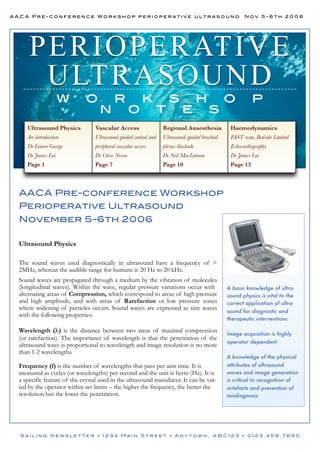
- 1. AACA Pre-conference Workshop perioperative ultrasound Nov 5-6th 2006 P ERI O P ERATI V E U LTRA S O U N D w o n r o k t s e h s o p Ultrasound Physics Vascular Access Regional Anaesthesia Haemodynamics An introduction Ultrasound-guided central and Ultrasound-guided brachial FAST scan, Bedside Limited Dr Lenore George peripheral vascular access plexus blockade Echocardiography Dr James Lai Dr Chris Nixon Dr Neil MacLennan Dr James Lai Page 1 Page 7 Page 10 Page 13 AACA Pre-conference Workshop Perioperative Ultrasound November 5-6th 2006 Ultrasound Physics The sound waves used diagnostically in ultrasound have a frequency of > 2MHz, whereas the audible range for humans is 20 Hz to 20 kHz. Sound waves are propagated through a medium by the vibration of molecules (longitudinal waves). Within the wave, regular pressure variations occur with alternating areas of Compression, which correspond to areas of high pressure and high amplitude, and with areas of Rarefaction or low pressure zones where widening of particles occurs. Sound waves are expressed as sine waves with the following properties: Wavelength (λ) is the distance between two areas of maximal compression (or rarefaction). The importance of wavelength is that the penetration of the ultrasound wave is proportional to wavelength and image resolution is no more than 1-2 wavelengths. Frequency (f) is the number of wavelengths that pass per unit time. It is measured as cycles (or wavelengths) per second and the unit is hertz (Hz). It is a specific feature of the crystal used in the ultrasound transducer. It can be varied by the operator within set limits – the higher the frequency, the better the resolution but the lower the penetration. A basic knowledge of ultrasound physics is vital to the correct application of ultrasound for diagnostic and therapeutic interventions Image acquisition is highly operator dependent A knowledge of the physical attributes of ultrasound waves and image generation is critical to recognition of artefacts and prevention of misdiagnosis Sailing Newsletter • 1234 Main Street • Anytown, ABC123 • 0123.456.7890
- 2. AACA Pre-conference Workshop perioperative ultrasound Nov 5-6th 2006 P H Y S I CS Interaction of Ultrasound with tissue Can be described by attenuation, reflection, scattering, refraction and diffraction. Attenuation Propagation Velocity (v) is the speed that sound waves propagate through a medium and depends on tissue density and compressibility. The relationship between these variables is expressed by the Wave Equation v = λf In soft tissue propagation velocity is relatively constant at 1540 m/sec and this is the value assumed by ultrasound machines for all human tissue. Hence wavelength is inversely proportional to frequency. Amplitude is the height above the baseline and represents maximal compression. It is expressed in decibels which is a logarithmic scale. Acoustic Power is the amount of acoustic energy generated per unit time. Energy is measured in joules (J) with joules being the amount of heat generated by the energy in question. The unit is the Watt (W) with 1W = 1J/sec. The biological effects of ultrasound in terms of power are in the milliwatt range. Intensity is the power density or concentration of power within an area expressed as Watts/m2 or mW/ cm2. Intensity varies spacially within the beam and is greatest in the centre. In a pulsed beam it varies temporally as well as spacially The loss of ultrasound as a medium is traversed. Occurs due to absorption of ultrasound energy by conversion to heat as well as reflection, refraction and scattering. Attenuation is increased (and hence penetration of beam reduced) by: • Increased distance from the transducer • Less homogenous medium to traverse due to increased acoustic impedance mismatch. • Higher frequency (shorter wavelength) transducers Air forms a virtually impenetrable barrier to ultrasound, while fluid offers the least resistance. Reflection Ultrasound waves are reflected at tissue boundaries and interfaces. These reflected echoes return to the transducer and form the basis of all ultrasound imaging. The amount reflected depends on the difference in acoustic impedance between the two tissues traversed by the beam. The Acoustic Impedance (Z) is a measure of how ultrasound traverses that tissue and depends on: • density of the medium (p) • propagation velocity of ultrasound through the medium (v) such that Z=pv A large difference in acoustic impedance is referred to as acoustic impedance mismatch. The greater the acoustic mismatch the greater the % of ultrasound reflected and the less transmitted. Examples include soft tissue/ bone and soft tissue/ air interfaces. Indeed, the acoustic impedance of gas or air is such that it forms a virtually impenetrable barrier to ultrasound. Sailing Newsletter • 1234 Main Street • Anytown, ABC123 • 0123.456.7890
- 3. AACA Pre-conference Workshop perioperative ultrasound Nov 5-6th 2006 P H Y S I CS Refraction When an ultrasound beam encounters media of different velocities, the proportion of the beam that is not reflected but is transmitted undergoes refraction or bending. These phenomena are responsible for some artefacts such as double image artefact. It also can allow for improved image quality by the use of acoustic lenses that can focus the ultrasound beam and improve resolution. Diffraction The ultrasound beam spreads out with distance from the transducer. This has the effect of lessening the intensity of the beam. Transducers Ultrasound waves are generated by piezoelectric crystals. Piezoelectric = “pressure electric” effect. When an electrical current is applied to a quartz crystal its shape changes with polarity. This causes expansion and contraction that in turn leads to the production of compression and rarefaction of sound waves. The reverse is also true and an electrical current is generated on exposure to returning echoes that are processed to generate a display. Hence the crystals are both transmitter (small proportion of the time) and receiver (most of the time). The frequency of the generated wave is a specific feature of the crystal used. Modern transducers use multiple small elements to generate the ultrasound wave. If a single small element transducer is used the waves radiate from it in a circular fashion as do ripples in a pool. If multiple small elements fire simultaneously however the individual curved wave fronts combine to form a linear wave front moving perpendicularly away from the transducer face. This system, that is multiple small elements fired individually, is termed phased array. Near field and Focusing In a standard disc shaped transducer the beam shape is cylindrical. Initially the beam is of comparable diameter to the transducer as the series of ultrasound waves that make up the beam travel parallel to each other. This is the near-field or Fresnel zone. At some point distal to the transducer however the beam begins to diverge which will reduce the ability to distinguish two objects close together (resolution). Beyond the point at which the beam begins to diverge is the far-field or Fraunhofer zone. It is possible to focus the ultrasound beam to cause convergence and narrowing of the beam thus improve (lateral) resolution. Focusing can be achieved by either mechanical or, in a phased array element, by electronic means. If the transducer face is concave or a concave acoustic lens is placed on the surface of the transducer, the beam can be narrowed at a predetermined distance from the transducer. The point at which the beam is at its narrowest is the focal point or focal zone and is the point of greatest intensity and best lateral resolution. Sailing Newsletter • 1234 Main Street • Anytown, ABC123 • 0123.456.7890
- 4. AACA Pre-conference Workshop perioperative ultrasound Nov 5-6th 2006 P H Y S I CS Resolution This is the ability to distinguish / identify two objects. It includes spatial and temporal resolution. Spatial resolution is the ability to distinguish two separate objects that are close together and is itself divided into Axial Resolution, which is this ability along the axis of the ultrasound beam, and Lateral Resolution, which is in the direction perpendicular to the beam's axis. Temporal resolution is the ability to accurately locate structures or events at a particular instant in time Lateral Resolution: The ability to distinguish objects that are side by side. It is generally poorer than axial resolution and is dependent on beam width. As the ultrasound machine assumes that any object visualised originates from the centre of the beam then two objects side by side cannot be distinguished if they are separated by less than the beam width. The determinants of beam width Transducer frequency (beam width increases with lower frequency transducers) Focusing of the beam Gain (increased gain will increase the beam width and reduce resolution) To optimise lateral resolution therefore: • Use highest frequency transducer (but note that this occurs at the expense of penetration). • Optimise the focal zone. • Use the minimum necessary gain (see the knobology section). Narrowing the Sector to the area of interest - narrowing the sector angle. Minimise Line density (but at the expense of lateral resolution). Artefacts The ultrasound machine makes various assumptions in generating an image. These include: • The ultrasound beam only travels in a straight line with a constant rate of attenuation. • The speed of sound in all body tissues is 1540m/s. • The ultrasound beam is infinitely thin with all echoes originating from its central axis. • The depth of a reflector is accurately determined by the time taken for sound to travel from the transducer to the reflector and return. Reverberation artefact This occurs when ultrasound is repeatedly reflected between two highly reflective surfaces. If for example, the transducer acts as another reflective surface to a returning echo, this echo will then be re-reflected and retrace itself resulting in an artefactual image identical, but at twice the distance from the transducer, as the real image. Due to the process of attenuation, each subsequent echo is weaker than the first. Axial Resolution: The ability to recognise two different objects at slightly different depths from the transducer along the axis of the ultrasound beam. Axial resolution = spatial pulse length (SPL) 2 where SPL = λ * no. of cycles It is improved by higher frequency (shorter wavelength) transducers but at the expense of penetration. Higher frequencies therefore are used to image structures close to the transducer. Temporal Resolution is dependent on frame rate. It is improved by: Minimising Depth - the maximum distance from the transducer as this affects the PRF. A is the true anatomical structure strongly reflective of ultrasound. A1 is the artefact generated by the returning ultrasound beam being re-reflected from the transducer and again reflected from the true anatomical structure at A. As this doubly reflected beam has travelled twice as far it is seen at twice the distance from the transducer. It is weaker but otherwise identical to the real structure at A. Sailing Newsletter • 1234 Main Street • Anytown, ABC123 • 0123.456.7890
- 5. AACA Pre-conference Workshop perioperative ultrasound Nov 5-6th 2006 P H Y S I CS A Mirror Image artefact is a type of reverberation artefact occurring at highly reflective air / fluid interfaces such as the lung and descending aorta. The first image is displayed in the correct position while a false image is produced on the other side of the reflector due to its mirror like effect. Side Lobe artefacts Side lobe beams are generated from the edges of the transducer element and project in a different direction from the main beam. These echoes are much weaker than those of the main beam but if a very strong reflector is encountered they may be strong enough on returning to the transducer to be displayed prominently on the image. Because any returning echoes are always assumed by the machine to have been generated from the main beam, their position on the display is incorrect (although at the right depth as time taken to and from transducer is the same. Multiple side lobe echoes as from a rapidly oscillating beam, are displayed as a curved line equidistant from the transducer along its length. The two most important features that distinguish a side lobe artefact from an anatomical structure are that it is equidistant to the transducer along its length and it passes through anatomical structures. Multipath artefact arises when the path of the ultrasound beam to and from a reflector is different. Part of the original echo returns to the transducer while part is reflected off a second interface before returning. As the second echo takes longer to return it is displayed deeper, but along the same line as the first. Beamwidth artefacts We assume the ultrasound beam is razor thin but in fact it has a measurable thickness. Any echoes generated from the beam’s edge will be displayed as though they have arisen from its centre. This is most apparent when most of the beam travels through fluid but part of the beam interacts with adjacent soft tissue. Echoes from this interface will be displayed as having arisen from inside the chamber. The intensity of the artefact decreases with distance. Propagation speed errors Occur when the media through which the ultrasound beam passes does not propagate at 1540 m/s result- ing in these echoes appearing at incorrect depths on the display. These speed errors can make the image appear “split” or “cut”. Acoustic shadowing A shadow results when an ultrasound beam is unable to pass through an area deep to a strongly reflecting or attenuating structure. It occurs deep to a region of high acoustic impedance mismatch such as soft tissue / gas or soft tissue / calcification interfaces. It is seen for example, deep to areas of calcification and prosthetic material. Tissue dropout occurs due to poor beam penetration and may result in misdiagnoses of defects such as septal defect. Incorrect gain Excess gain can create or obscure information and reduce lateral resolution. This is of great importance when attempting to planimeter calcified valves as increased gain will artificially reduce the valve area. Incorrect gain or focal zone setting may give an erroneous appearance of spontaneous echo contrast (SEC). True SEC can be distinguished by a “swirling” pattern as distinct from the grainy appearance of high gain settings. Near field clutter This is due to acoustic noise near the transducer, resulting from high amplitude oscillations of the piezoelectric elements, and can make distinguishing structures within 1 cm of the transducer very difficult. In general, artefacts change their appearance and appear or disappear depending on the view. Real structures will remain constant and can be seen in multiple views. By using appropriate settings, understanding the imaging principles and knowing echocardiographic anatomy, it should be possible to readily distinguish artefacts and pitfalls from real structures. Reference This article is based on “Ultrasound Physics”, a chapter in the Westmead TOE Manual by Dr Lenore George, Consultant Anaesthetist, Westmead Hospital, Sydney. Sailing Newsletter • 1234 Main Street • Anytown, ABC123 • 0123.456.7890