2. 2-2
This is the lowest possible noise level for a system with a
given physical temperature. For most applications,
temperature is typically assumed to be room temperature
(290K). Equations 1 and 2 demonstrate that RF power and
bandwidth can be traded off to achieve a given performance
level (as defined by BER).
Range and Path Loss
Another key consideration is the issue of range. As radio
waves propagate in free space, power falls off as the square
of range. For a doubling of range, power reaching a receiver
antenna is reduced by a factor of four. This effect is due to
the spreading of the radio waves as they propagate, and can
be calculated by:
where:
D = the distance between receiver and transmitter
λ = free space wavelength = c/f
c = speed of light (3 x 10⁸ m/s)
f = frequency (Hz)
Equation 3 above describes line-of-sight, or free space
propagation. Because of building obstructions such as walls
and ceilings, propagation losses indoors can be significantly
higher. This occurs because of a combination of attenuation by
walls and ceilings, and blockage due to equipment, furniture,
and even people. For example, a “2 x 4” wood stud wall with
sheetrock on both sides results in about 6dB loss per wall.
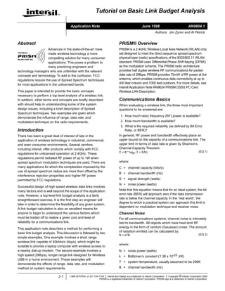
Experience has shown that line-of-sight propagation holds only
for about the first 20 feet. Beyond 20 feet, propagation losses
indoors increase at up to 30dB per 100 feet (see Figure 1) in
dense office environments. This is a good “rule-of-thumb”, in
that it is conservative (it overstates path loss in most cases).
Actual propagation losses may vary significantly depending on
building construction and layout.
R
Multipath and Fade Margin
Multipath occurs when waves emitted by the transmitter
travel along a different path and interfere destructively with
waves travelling on a direct line-of-sight path. This is
sometimes referred to as signal fading. This phenomenon
occurs because waves travelling along different paths may
be completely out of phase when they reach the antenna,
thereby canceling each other.
Since signal cancellation is almost never complete, one
method of overcoming this problem is to transmit more
power. In an indoor environment, multipath is almost always
present and tends to be dynamic (constantly varying).
Severe fading due to multipath can result in a signal
reduction of more than 30dB. It is therefore essential to
provide adequate link margin to overcome this loss when
designing a wireless system. Failure to do so will adversely
affect reliability.
The amount of extra RF power radiated to overcome this
phenomenon is referred to as fade margin. The exact
amount of fade margin required depends on the desired
reliability of the link, but a good rule-of-thumb is 20dB to
30dB.
One method of mitigating the effects of multipath is antenna
diversity. Since the cancellation of radio waves is geometry
dependent, use of two (or more) antennas separated by at least
half of a wavelength can drastically mitigate this problem. On
acquisition of a signal, the receiver checks each antenna and
simply selects the antenna with the best signal quality. This
reduces, but does not eliminate, the required link margin that
would otherwise be needed for a system which does not
employ diversity. The downside is this approach requires more
antennas and a more complicated receiver design.
Another method of dealing with the multipath problem is via
the use of an adaptive channel equalizer. Adaptive
equalization can be used with or without antenna diversity.
(EQ.3)L = 20 log10 (4π D / λ)
FIGURE 1. ESTIMATED INDOOR PROPAGATION LOSSES AT
2.4GHz
130
120
110
100
90
80
70
60
50
20 40 60 80 100 120 140 160 180 200 220 240
RANGE (FT)
PATHLOSS(dB)
FREE SPACE
INDOOR
FIGURE 2. MULTIPATH
MULTIPATH SIGNAL #2
BUILDING
STRUCTURE
DIRECT PATH SIGNAL
M
ULTIPATH
SIG
NAL
#1
OFFICE
FURNITURE
TX
RX
Application Note 9804
3. 2-3
After the signal is received and digitized, it is fed through a
series of adaptive delay stages which are summed together
via feedback loops. This technique is particularly effective in
slowly changing environments such as transmission over
telephone lines, but is more difficult to implement in rapidly
changing environments like factory floors, offices and homes
where transmitters and receivers are moving in relation to
each other. The main drawback is the impact on system cost
and complexity. Adaptive equalizers can be expensive to
implement for broadband data links.
Spread spectrum systems are fairly robust in the presence
of multipath. Direct Sequence Spread Spectrum (DSSS)
systems will reject reflected signals which are significantly
delayed relative to the direct path or strongest signal. This is
the same property which allows multiple users to share the
same bandwidth in Code Diversity Multiple Access (CDMA)
systems. Frequency Hopping Spread Systems (FHSS) also
exhibit some degree of immunity to multipath. Because a
FHSS transmitter is continuously changing frequencies, it
will always hop to some frequencies which experience little
or no multipath loss. In a severe fading environment,
throughput of an FHSS system will be reduced, but it is
unlikely that the link will be lost completely. The performance
of DSSS systems in the presence of multipath is described
further in a separate section below.
Modulation Technique
Modulation technique is a key consideration. This is the
method by which the analog or digital information is
converted to signals at RF frequencies suitable for
transmission. Selection of modulation method determines
system bandwidth, power efficiency, sensitivity, and
complexity. Most of us are familiar with Amplitude
Modulation (AM) and Frequency Modulation (FM) because
of their widespread use in commercial radio. Phase
Modulation is another important technique. It is used in
applications such as Global Position System (GPS)
receivers and some cellular telephone networks.
For the purposes of link budget analysis, the most important
aspect of a given modulation technique is the Signal-to-
Noise Ratio (SNR) necessary for a receiver to achieve a
specified level of reliability in terms of BER. A graph of Eb/No
vs BER is shown in Figure 4. Eb/No is a measure of the
required energy per bit relative to the noise power. Note that
Eb/No is independent of the system data rate. In order to
convert from Eb/No to SNR, the data rate and system
bandwidth must be taken into account as shown below:
where:
Eb = Energy required per bit of information
No= thermal noise in 1Hz of bandwidth
R = system data rate
BT= system bandwidth
Spread Spectrum Radios
The term “spread spectrum” simply means that the energy
radiated by the transmitter is spread out over a wider amount
of the RF spectrum than would otherwise be used. By
spreading out the energy, it is far less likely that two users
sharing the same spectrum will interfere with each other.
This is an important consideration in an unlicensed band,
which why the regulatory authorities imposed spread
spectrum requirements on radios which transmit over -1dBm
(about 0.75mW) in the following bands:
FIGURE 3. ADAPTIVE EQUALIZER
∑
W1 W2 W3 W4 Wn
Z-1 Z-1 Z-1 Z-1
DIGITAL EQUALIZER OUT
DIGITIZED
BASEBAND
INPUT
TABLE 1. TYPICAL BANDWIDTHS FOR VARIOUS DIGITAL
MODULATION METHODS
MODULATION METHOD
TYPICAL BANDWIDTH
(NULL-TO-NULL)
QPSK, DQPSK 1.0 x Bit Rate
MSK 1.5 x Bit Rate
BPSK, DBPSK, OFSK 2.0 x Bit Rate
FIGURE 4. PROBABILITY OF BIT ERROR FOR COMMON
MODULATION METHODS
0 1 2 3 4 5 6 7 8 9 10 11 12 13 14 15
Eb/No (dB)
1.0E-01
1.0E-02
1.0E-03
1.0E-04
1.0E-05
1.0E-06
1.0E-07
BE
INCOHERENT OOK, OFSK
COHERENT OOK, OFSK
DBPSK, DQPSK
MSK, PSK
(EQ.4)SNR = (Eb/No) * (R/BT)
Application Note 9804
4. 2-4
In the U.S., these bands are collectively designated as
Industry, Science, and Medicine (ISM) bands. Operation in
these bands with approved devices does not require an FCC
license. By waiving licensing requirements, these bands
have been made generally accessible to virtually anyone.
This is mainly why the ISM bands are so important for
commercial and consumer applications.
As mentioned above, radios employing spread spectrum
methods are allowed to radiated up to 1.0W (30dBm) of RF
energy, as compared to less than 1mW for non-spread
radios. There are two common types of spread spectrum
systems. The easiest to understand is Frequency Hopped
Spread Spectrum (FHSS). In this method, the carrier
frequency hops from channel to channel in some pre-
arranged sequence. The receiver is programmed to hop in
sequence with the transmitter. If one channel is jammed, the
data is simply retransmitted when the transmitter hops to a
clear channel. The major drawback to FHSS is limited data
rate. In the 2.4GHz band, FCC regulations require that the
maximum occupied bandwidth for any single channel is
1MHz. This effectively limits the data rate through this type
of system to about 1Mbps.
By contrast, Direct Sequence Spread Spectrum (DSSS)
systems in the ISM bands provide much higher data rates.
DSSS systems do not jump from frequency to frequency.
Instead, the transmitter actually spreads the energy out over
a wider portion of the RF spectrum. This can be
accomplished by combining the data stream with a much
higher rate Pseudo Random Numerical (PRN) sequence via
an XOR function. The result is a digital stream at the same
rate as the PRN. When the RF carrier is modulated by the
higher speed digital stream, the result is a spreading of the
RF energy.
The individual 1’s and 0’s that make up the PRN are called
“chips”. They are distinct from the “bits” in the data stream
because chips are predetermined by the PRN sequence and
hence, contain no information. The ratio of the chip rate (C)
to the data rate (R) is called processing gain. In the PRISM
radio, this ratio is selectable. It can be set to 11, 13, 15, or 16
chips/bit. The IEEE 802.11 Standard specifies an 11 chip PN
sequence (Barker code), which will be used for this example.
At the receiver, the pseudo random code is used to
“de-spread” the received data. In the PRISM chip set, this is
accomplished by means of a matched filter at baseband. It is
during this process that the matched filter rejects unwanted
interference because it is uncorrelated with the PRN. By
careful selection of the PRN sequence, the matched filter
provides an additional benefit. It can reject multipath signals
which are delayed relative to the main signal by more than
one chip period, or about 44ns. In this manner, it provides
some of the benefits of the adaptive equalizer shown in
Figure 3, though its operation and implementation are much
simpler.
TABLE 2. WORLD WIDE UNLICENSED FREQUENCY
ALLOCATION RF POWER LIMITS
BAND
FCC REGS
(US)
ETSI
(EUROPE)
MPT
(JAPAN)
902 - 928MHz <1000mW N/A N/A
2400 - 2483.4MHz <1000mW <100mW N/A
2471 - 2497MHz N/A N/A <10mW/MHz
5725 - 5875MHz <1000mW <100mW N/A
FIGURE 5. FHSS SPECTRUM UTILIZATION
t-5 t-2 t0 t-1 t-4 t-3
2.400GHz 2.483GHz
FIGURE 6. COMBINING PRN SEQUENCE AND DATA
DATA
OUT
PRN
1-BIT
PERIOD
11 CHIPS
11 CHIPS 1-BIT
11-BIT BARKER CODE (PRN):
1 0 1 1 1 0 1 0 0 0
01000101111011101000
(EQ.5)Processing Gain = 10log10(C/R) = 10.4dB
FIGURE 7A. TRANSMITTER BASEBAND SIGNAL BEFORE
SPREADING
FIGURE 7B. TRANSMITTER BASEBAND SIGNAL AFTER
SPREADING
Application Note 9804
5. 2-5
If viewed on a spectrum analyzer, the de-spreading process
would cause the received spectrum to decrease in width by
a factor of 11:1, while at the same time causing the peak in
the spectrum to increase in amplitude by the same amount.
This is why this effect is called processing gain.
Example 1: Wireless Link to Dial-Up Modem
As an example, consider a data link intended to provide a
wireless link between a laptop computer and a dial-up
modem in a home environment as shown in Figure 10. In
order to support a throughput of 28.8kbps, the link should be
designed for about 40kbps. The additional data rate is
needed to accommodate framing, overhead, checksums
which may be required for the wireless link.
Example 1: Requirements
Required data rate = 40kbps
(28.8kbps plus framing, overhead, and checksum)
Range =5 meters
Desired BER =10-6
Example 1: FCC and ETSI Regulations
For unlicensed systems not employing spread spectrum
techniques, RF power is limited to -1.25dBm, or about
0.75mW. For details on RF power limitations, refer to FCC
Regulations 15.247 and 15.249. If spreading is employed,
RF power can be increased to 1W (U.S. operations). For
Europe, ETSI regulations (ETSI 300, 328) limit RF power for
spread spectrum radios to 20dBm, or 100mW. Spreading is
therefore attractive because it allows for transmission of up
to 1000 times more RF power.
Example 1: So, Should Spread Spectrum
Techniques Be Used In This Case?
Spread spectrum offers some interference rejection
properties, but it also entails higher complexity. Therefore,
the application should first be evaluated to determine if it can
be reliably serviced by a low power, non-spread spectrum
radio. If not, then spread spectrum high power radios should
be considered.
FIGURE 8. MATCHED FILTER CORRELATOR
Z-1
2N
Z-1
6
Z-1
5
Z-1
4
Z-1
3
Z-1
2
Z-1
1
∑
R1 R2 R3 RN N = 16
SYMBOL PERIOD
CHIP
PERIOD
CORRELATION SCORE
A/D
SAMPLE
CLOCK
PARALLEL PN
REGISTER LOAD
RX DATA
FROM ADCs
2X CHIP CLOCK
11-BIT BARKER CODE EXAMPLE:
+1 -1 +1 +1 -1 +1 +1 +1 -1 -1 -1
FIGURE 9A. RECEIVER BASEBAND SIGNAL BEFORE
MATCHED FILTER CORRELATOR
FIGURE 9B. RECEIVER BASEBAND SIGNAL AFTER
MATCHED FILTER CORRELATOR
FIGURE 10. EXAMPLE 1: WIRELESS LINK TO MODEM
RF
XCVR
28.8KBPS
MODEM
PHONE
LINE
LAPTOP
PC
RF
XCVR
Application Note 9804
6. 2-6
Example 1: Frequency Selection
There are several bands available for unlicensed operation
(see Table 2). As described previously, in the Multipath and
Fade Margin section, the higher the frequency, the higher
the propagation loss. Therefore, a lower frequency is better
in terms of propagation loss. It is generally less expensive to
build radios at lower frequencies. Other considerations
include available bandwidth and regulatory limitations. The
available bands are 900MHz, 2.4GHz, and 5.725GHz. The
easy choice is 900MHz, but this band is getting crowded with
things like cordless phones. For such a short link, 900MHz is
still a good choice.
Example 1: Modulation Technique
There are lots of choices here. The Intersil PRISM radio chip
set uses Phase Shift Keying (PSK) modulation, but some of
the motivating factors behind this choice are not applicable
in this instance. A simpler method is Frequency Shift Keying
(FSK). FSK is actually a form of Frequency Modulation (FM),
which has been around for a long time. With FSK, two
separate frequencies are chosen, one frequency
representing a logical “zero”, the other representing logical
“one”. Data is transmitted by switching between the two
frequencies.
A good choice of modulation would therefore be FSK. The
separation of two frequencies relative to the bit rate is called
modulation index (h).
h = frequency separation / bit rate
= ∆f / R
A modulation index of 1 (h = 1) is a good choice for a low
cost application, unless there are restrictions on bandwidth.
When h = 1, the frequencies are said to be orthogonal. This
form of modulation is called Orthogonal FSK, or OFSK.
Choosing h = 1 results in a simple but fairly robust receiver
design. In this case, the frequencies would be separated by
40kHz.
Example 1: System Bandwidth and Noise Floor
In general, the modulation technique dictates the required
system bandwidth (or visa versa, depending on design
constraints). For FSK modulation and h = 1, the bandwidth is
typically about 2 times the data rate (see Table 1), or 80kHz.
We therefore can compute the noise power:
= 1.38 x 10⁻²³ J/K x 290K x 80,000 s-1
= 2.4 x 10⁻¹³mW
= -126dBm
This figure represents a theoretical noise floor for an ideal
receiver. A real receiver noise floor will always be higher, due
to noise and losses in the receiver itself. Noise Figure (NF) is
a measure of the amount of noise added by the receiver
itself. A typical number for a low cost receiver would be
about 15dB. This number must be added to the thermal
noise to determine the receiver noise floor:
= -111dBm
Example 1: Receiver Sensitivity
The first step in performing the link budget is determining the
required signal strength at the receiver input. This is referred
to as receiver sensitivity (Prx). As described previously, this
is a function of the Modulation Technique and the desired
BER. A graph of Eb/No vs BER is shown in Figure 2. For the
case at hand, the modulation technique is OFSK. For 10-6
BER:
= 26.3 * (40kbps / 80kHz)
= 11dB
= -111dBm + 11dB
= -100dBm
Example 1: Link Calculation
Propagation loss (Lfs) can be computed as:
= 20 x log10(4 * pi * 5 meters/0.33 meters)
= 46dB
Note: lambda is the free space wavelength at the carrier
frequency
λ = c/f
= 3 x 10⁸ms-1/900MHz
= 0.33 meters
Finally, some assumption must be made about transmit and
receive antenna gain values. For a simple dipole antenna,
an assumption of 0dB gain is reasonable. This number will
be taken for the gain of both the transmit antenna gain
(Gtx)and receive antenna gain (Grx). Now, the required
transmitter power (Ptx) can be computed:
= -100dBm - 0dB - 0dB + 46dB + 30dB
= -24dBm
Example 1: Conclusions
This exercise shows that the wireless modem link can be
reliably served by an OFSK radio operating at 900MHz using
as little as -24dBm transmit power. FCC regulations permit
(EQ.6)N = kTB
(EQ.7)Receiver Noise Floor = -126dBm + 15dB
(EQ.8)Eb/No = 14.2dB = 26.3
(EQ.9)SNR = (Eb/No) * (R/BT)
(EQ. 10)Prx = Receiver Noise Floor + SNR
(EQ. 11)Lfs = 20 x log10(4 * pi * D/lambda)
(EQ. 12)Ptx = Prx - Gtx - Grx + Lfs + Fade Margin
Application Note 9804
7. 2-7
transmission of up to -1.25dBm in the unlicensed bands
without requiring spread spectrum modulation. However, as
mentioned above, the 900MHz band is becoming crowded.
This is particularly true for consumer application due to the
proliferation of cordless telephones. If this is considered a
major problem, the above analysis can easily be re-
evaluated assuming a carrier frequency in other unlicensed
bands such as 2.4GHz, or even 5GHz.
In addition to the analysis of the radio link itself, there are
other considerations beyond those mentioned here. These
include the suitability of the modem protocol to packet mode
transmission, synchronization of data rates, etc. The
foregoing discussion focused on the link analysis and is by
no means exhaustive. It is intended to illustrate top level
trades involving data rate, range, and choice of modulation.
Example 2: Wireless USB - An Ideal
Application for PRISM
Having shown that PRISM is not the optimal choice for a
short-haul, low bit rate wireless link such as the wireless
modem described above, a more suitable application will
now be explored. Universal Serial Bus (USB) is rapidly
replacing the serial port on personal computers. USB
provides high speed flexible interconnectivity between a PC
and its peripherals. Despite its flexibility, USB has a range
limitation of 5 meters.
USB has two modes of signaling. The full speed signaling
rate is 12Mbps, while the low rate is 1.5Mbps. The low speed
rate is designed to support devices such as mice and
keyboards. However, a radio capable of providing 1.5Mbps
throughput could be used in a wireless hub application,
though it could not support the full hi-speed rate of 12Mbps.
A wireless hub could support bulk transfers, and possibly
isochronous applications such as wireless audio and
MPEG1 video if rate buffering were available at the transmit
side of the link.
In this example, a wireless digital link capable of 1.5Mbps
throughput at up to 100 feet indoors is desired. As in the
previous example, a somewhat higher data rate will be
required in order to accommodate framing, overhead, and
checksum for the wireless link. Typically, throughput is about
70% to 75% of peak data rate. Therefore, the required data
rate for the wireless link is roughly 2Mbps.
Example 2: Requirements
Data Rate = 2Mbps (1.408Mbps + framing, overhead,
checksum)
Range = 30 meters indoors (100 feet)
Desired BER = 10-6
Example 2: Should I Use a Spread Spectrum
Radio?
In the previous example, spreading was not required.
However, there are a couple of major differences with this
example. The data rate is much higher and the range is a
farther. Therefore, due to FCC restrictions on transmitted
power for non-spread spectrum transmitters in the
unlicensed bands, the non-spread OFSK radio described in
Example 1 above will not be capable of meeting this far more
stringent application. By contrast, Intersil’s PRISM radio was
designed specifically for such demanding applications. It
employs spread spectrum techniques and can radiate up to
1W of RF power according to FCC regulations (FCC
15.247).
Example 2: Frequency Selection
As described previously, there are several bands allocated
for unlicensed operation. There is spectrum at 902-928MHz.
However, this band is getting pretty crowded. Another
consideration is the limited bandwidth. There is only 26MHz
in this band. A better choice would be the 2.400 - 2.483GHz.
There is less radio traffic in this band (although there is
potential interference from microwave ovens), and the total
available bandwidth is 83MHz. In addition, this frequency
band is approved for unlicensed operation in the U.S.,
Europe, and Japan.
Example 2: Modulation Technique
PRISM utilizes Differential Binary Phase Shift Keyed
(DBPSK) modulation to transmit data at up to 1Mbps, and
Differential Quadrature Phase Shift Keyed (DQPSK)
modulation to transmit data up to 2Mbps. The main
advantage of DQPSK is spectral efficiency. The null-to-null
bandwidth for a DQPSK radio is about the same as the data
rate (R).
RF
RECEIVER
RF
RECEIVER
DESKTOP
PC
USB
RF
TRANSMITTER
WIRELESS
USB HUB
LEFT SPEAKER RIGHT SPEAKER
FIGURE 11. WIRELESS USB LINK
Application Note 9804
8. 2-8
All Intersil semiconductor products are manufactured, assembled and tested under ISO9000 quality systems certification.
Intersil semiconductor products are sold by description only. Intersil Corporation reserves the right to make changes in circuit design and/or specifications at any time with-
out notice. Accordingly, the reader is cautioned to verify that data sheets are current before placing orders. Information furnished by Intersil is believed to be accurate and
reliable. However, no responsibility is assumed by Intersil or its subsidiaries for its use; nor for any infringements of patents or other rights of third parties which may result
from its use. No license is granted by implication or otherwise under any patent or patent rights of Intersil or its subsidiaries.
For information regarding Intersil Corporation and its products, see web site http://www.intersil.com
Example 2: System Bandwidth and Noise Floor
For 2Mbps, the occupied bandwidth of a PRISM transmitter
would be 22MHz due to spreading. Due to the 11:1 ratio
between the chip rate (C) and the data rate (R), the radio is
transmitting 22Mcps. This results in an occupied bandwidth
of 22MHz (see Figure 7). However, after the de-spreading at
the receiver, the bandwidth at baseband would be restored
to 2MHz (see Figure 8). It is important to note that although
PRISM is a spread spectrum radio, the noise floor is
computed using the de-spread bandwidth:
= 1.38 x 10⁻²³ J/K x 290K x 2,000,000 s-1
= 4 x 10-12mW
= -113dBm
PRISM has a receiver noise figure of 7dB. The receiver
noise floor is then:
= -104dBm
From Figure 1, the free space path loss at 100 feet for indoor
propagation may be determined. This value is 80dB. DQPSK is
an efficient modulation technique. The required Eb/No to
achieve a 10-6 BER is 11dB. The required signal-to-noise ratio
(SNR) and receiver sensitivity (Prx) can now be determined:
= 12.7 * (2Mbps / 2.0MHz)
= 11dB
= -104dBm + 11dB
= -93dBm
One of the characteristics of Direct Sequence Spread
Spectrum (DSSS) radios such as PRISM is reduction in the
effects of multipath. If the indirect signal is delayed by more
than a chip period, it will appear to the receiver as
uncorrelated random noise, and will not cancel the direct
signal. Therefore, an allocation of 30dB is an even more
conservative assumption for fade margin. Transmit and
receive antenna gain are unchanged from the previous
example (0dB). Using this data, the link budget may now be
recalculated:
= -93dBm - 0dB - 0dB + 80dB + 30dB
= 17dBm
FCC regulations permit DSSS systems to transmit up to 1W
(or 30dBm). The PRISM Radio chip set provides +18dBm
radiated power, which is ideal for this application. In addition,
the DSSS waveform provides an additional 10dB of rejection
of potential jammers, such as microwave ovens, arc welders,
and other industrial machinery.
Example 2: Conclusions
PRISM is an ideal solution for high bit rate (up to 2Mbps)
mobile data transmission. In addition to its robust waveform, it
features IEEE 802.11 compliant operation. It has a Carrier
Sense Multiple Access collision avoidance feature which
allows multiple users to share the same RF channel. The
programmable synthesizer allows for the collocation of several
channels to accommodate even more users. The highly
integrated chip set provides a complete Antenna-to-Bits
solution.
References
For Intersil documents available on the internet, see web site
www.intersil.com/
Intersil AnswerFAX (321) 724-7800.
[1] Modern Communications Systems, Couch, Leon W.,
Prentice-Hall, Inc., Englewood Cliffs, NJ, 1995. (ISBN
0-02-325286-3)
[2] Digital Communications Systems, Peebles, Peyton Z.,
Prentice-Hall, Inc., Englewood Cliffs, NJ, 1987. (ISBN
0-13-211970-6)
[3] Mobile Cellular Telecommunications Systems, Lee, Will-
iam C. Y., McGraw-Hill, New York, NY, 1989 (ISBN 0-
07-037030-3)
[4] Digital Communications, Proakis, John G., Second Edi-
tion, McGraw-Hill, New York, NY, 1989 (ISBN 0-07-
050937-9)
[5] Spread Spectrum Systems, Dixon, Robert C., Third Edi-
tion, John Wiley & Sons, New York, NY, 1994 (ISBN 0-
471-59342-7)
(EQ. 13)Noise = kTB
(EQ. 14)Rx Noise Floor = -111dBm + 7dB
(EQ. 15)Eb/No = 11dB = 12.7
(EQ. 16)SNR = (Eb/No) * (R/BT)
(EQ. 17)Prx = Receiver Noise Floor + SNR
(EQ. 18)Ptx = Prx - Gtx - Grx + Lfs + Fade Margin
Application Note 9804