Top Rated Pune Call Girls Budhwar Peth ⟟ 6297143586 ⟟ Call Me For Genuine Se...
ZSE30.pdf
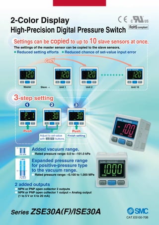
1. 2-Color Display
High-Precision Digital Pressure Switch
The settings of the master sensor can be copied to the slave sensors.
P Reduced setting efforts P Reduced chance of set-value input error
Settings can be
Settings can be copied
copied to up to
to up to 10
10 slave sensors at once.
slave sensors at once.
Settings can be copied to up to 10 slave sensors at once.
3
3-step setting
-step setting
3-step setting
Push
Push
Push
Finish setting
3
Push
Push
Push
1 2
Adjust to set-value
with buttons.
Added vacuum range.
P Rated pressure range: 0.0 to –101.0 kPa
2 added outputs
P NPN or PNP open collector 2 outputs
P NPN or PNP open collector 1 output + Analog output
(1 to 5 V or 4 to 20 mA)
–101 kPa
0
Master Unit 1
Slave → Unit 2 Unit 10
Cop
Copy
y
Copy
Expanded pressure range
for positive-pressure type
to the vacuum range.
P Rated pressure range: –0.100 to 1.000 MPa
1 MPa
0
–0.1 MPa
(–100 kPa)
CAT.ES100-70B
Series ZSE30A(F)/ISE30A
RoHScompliant
2. Withstand pressure
Minimum unit setting
Rated pressure range
R Secret code setting function
The key locking function keeps unauthorized persons
from tampering with buttons.
R Power-saving function
Power consumption is reduced by turning off the
monitor. (Reduce power consumption by up to 20%.)
R Resolution-switch function
It reduces the monitor to flicker.
R MPa/kPa switch function
Vacuum, compound and/or positive pressure can be
displayed in MPa or kPa.
Bracket configuration allows mounting in four orientations. The clip type allows easy removal of fittings.
Fitting’s type and size can be changed.
Series
–0.100 to 1.000 MPa
1 MPa
0
–0.1MPa
(–100 kPa)
ISE30A (positive)
0.0 to –101.0 kPa
–101 kPa
0
ZSE30A (vacuum)
–100.0 to 100.0 kPa
–100 kPa
100 kPa
0
ZSE30AF (compound)
0.001 MPa
0.1 kPa
500 kPa
500 kPa
0.1 kPa
NPN or PNP open collector 1 output
NPN or PNP open collector 2 outputs
NPN or PNP open collector 1 output + Analog output (voltage or current)
Output
R1/8, NPT1/8 (M5 female threaded)
ø4, ø6, ø5/32, ø1/4 One-touch fittings
Piping
Set pressure range –0.105 to 1.050 MPa
–105.0 to 105.0 kPa
10.0 to –105.0 kPa
Bracket A Bracket B/C
Mounting
example
Bracket B
Mounting
example
Bracket C
Mounting
example
Panel mount
Mountable side by side
without clearance
One opening!
• Reduction of panel-cut job
• Space-saving
Replaceable One-touch fittings
Added the connector cover.
4-digit display allows easy reading of displayed values.
Example: 0.5 MPa
Lead wire
4-digit display
Additional functions
One-touch fitting
Clip
Lead wire with connector
(2 m)
Connector cover
Mounting
Series
1.5 MPa
Possible to check set-value during
key locking
Series 30A
(New)
Series 30
(Conventional)
(Accuracy is not changed, only the displayed values.)
1/1000 1/100
Features 1
3. How to Order
2-Color Display
High-Precision
Digital Pressure Switch
Series ZSE30A(F)/ISE30A
For vacuum/
compound pressure
ISE30A
For positive
pressure 01 N M
ZSE30A 01 N M
Rated pressure range
ISE30A –0.1 to 1 MPa
Output
NPN open collector 1 output
PNP open collector 1 output
NPN open collector 2 outputs
PNP open collector 2 outputs
NPN open collector 1 output + Analog voltage output
NPN open collector 1 output + Analog current output
PNP open collector 1 output + Analog voltage output
PNP open collector 1 output + Analog current output
N
P
A
B
C∗
D∗
E∗
F∗
Rated pressure range
ZSE30A
ZSE30AF
0 to –101 kPa
–100 to 100 kPa
Option 1
Without lead wire
Lead wire with connector
(Lead wire length 2 m) Note)
L
Lead wire with connector
(Lead wire length 2 m) Note)
With connector cover
G
Nil
Note) For output types N and P, the number of core of lead wires will
be 3, and for other types, it will be 4.
With unit display Note 1)
switching function
Fixed SI unit Note 2)
With unit display Note 1)
switching function
(Initial value psi)
Nil
P∗
M
Display unit
Note 1) Under the New Measure-
ment Law, sales of switches
with the unit switching func-
tion have not been allowed
for use in Japan.
Note 2) Fixed unit kPa, MPa
Piping
R1/8 (M5 female threaded)
NPT1/8 (M5 female threaded)
One-touch fitting ø4 mm, ø5/32 inch
One-touch fitting ø6 mm
One-touch fitting ø1/4 inch
One-touch fitting ø4 mm, ø5/32 inch
One-touch fitting ø6 mm
One-touch fitting ø1/4 inch
01
N01
C4H
C6H
N7H
C4L
C6L
N7L
Straight type
Elbow type
∗ Made to Order
∗ Made to Order
∗ Made to Order
∗
®
RoHS
Option 3
Symbol
Calibration
certificate
Nil
Y
K
T
Operating manual
Booklet
Option 2
None
Bracket A
A1
Bracket B
A2
Bracket C
A3
Panel mount adapter
B
Panel mount adapter + Front protection cover
D
Nil
Made to Order (P.12)
X510
For M12 4-pin
pre-wired connector
Available only for output “A” or “B”.
Connector cover
1
4. Specifications
Piping Specifications
Model 01 N01 C4H C6H
Sensor pressure receiving area: Silicon
C3602 (electroless nickel plated)
O-ring: HNBR
N7H C4L C6L N7L
—
ø1/4 inch
—
ø6 mm
—
ø4 mm
ø5/32 inch
ø1/4 inch
—
ø6 mm
—
—
—
—
—
—
—
ø4 mm
ø5/32 inch
—
NPT1/8
M5 x 0.8
—
R1/8
M5 x 0.8
— —
—
One-touch fitting, Straight type
One-touch fitting, Elbow type
Sensor pressure receiving area
Piping port
Including lead wire with connector (3 cores, 2 m)
Including lead wire with connector (4 cores, 2 m)
Excluding lead wire with connector
PBT, POM, Stainless steel 304, C3604 (electroless nickel plated)
O-ring: NBR
81 g
85 g
43 g
70 g
74 g
32 g
Port size
Wetted
parts
material
Weight
71 g
75 g
33 g
73 g
77 g
35 g
75 g
79 g
37 g
73 g
77 g
35 g
75 g
79 g
37 g
Optional Part No.
When optional parts are required separately, use the following part numbers to place an order.
ZS-38-A1
ZS-38-A2
ZS-38-A3
ZS-27-C
ZS-27-D
ZS-27-01
ZS-38-3L
ZS-38-4L
ZS-38-3G
Bracket A
Bracket B
Bracket C
Panel mount adapter
Panel mount adapter + Front protection cover
Front protection cover
Lead wire with connector
Lead wire with connector
Lead wire with connector (with connector cover)
Mounting screw (with 2 pcs. of M3 x 5L)
Mounting screw (with 2 pcs. of M3 x 5L)
Mounting screw (with 2 pcs. of M3 x 5L)
Mounting screw (with 2 pcs. of M3 x 8L)
Mounting screw (with 2 pcs. of M3 x 8L)
3 cores, for 1 output, 2 m
4 cores, for 2 outputs, 2 m
3 cores, for 1 output, 2 m
Part no. Option Note
ZS-38-4G
ZS-38-5L
ZS-38-U
ZS-38-C4H
ZS-38-C6H
ZS-38-N7H
ZS-38-C4L
ZS-38-C6L
ZS-38-N7L
Lead wire with connector (with connector cover)
Lead wire with a connector for copying
Lead wire unit with a connector for copying
One-touch fittings ø4 mm straight
One-touch fittings ø6 mm straight
One-touch fittings ø1/4 inch straight
One-touch fittings ø4 mm elbow
One-touch fittings ø6 mm elbow
One-touch fittings ø1/4 inch elbow
4 cores, for 2 outputs, 2 m
3 cores, copy function, 1 m
Copy function (up to 10 slaves)
O-ring, one-touch clip included
O-ring, one-touch clip included
O-ring, one-touch clip included
O-ring, one-touch clip included
O-ring, one-touch clip included
O-ring, one-touch clip included
Part no. Option Note
Note 1) If applied pressure fluctuates near the set value, set the hysteresis above the fluctuation range to prevent chattering.
Note 2) When analog voltage output is selected, analog current output cannot be used together.
Note 3) When analog current output is selected, analog voltage output cannot be used together.
Model ZSE30A (Vacuum pressure)
Rated pressure range
Set pressure range
Withstand pressure
Minimum unit setting
Applicable fluid
Power supply voltage
Current consumption
Switch output
Repeatability
Analog
output
Hystere-
sis
Display
Display accuracy
Indicator light
Environ-
ment
resistance
Temperature characteristics
Lead wire
Standards
0.0 to –101.0 kPa
10.0 to –105.0 kPa
500 kPa
0.1 kPa
0.6 to 5 V ±2.5% F.S.
ZSE30AF (Compound pressure)
–100.0 to 100.0 kPa
–105.0 to 105.0 kPa
500 kPa
0.1 kPa
Air, Non-corrosive gas, Non-flammable gas
12 to 24 VDC ±10%, Ripple (p-p) 10% or less (with power supply polarity protection)
40 mA or less
NPN or PNP open collector 1 output, NPN or PNP open collector 2 outputs (selectable)
80 mA
28 V (at NPN output)
1 V or less (with load current of 80 mA)
2.5 ms or less (with anti-chattering function: 20, 100, 500, 1000, 2000 ms)
Yes
±0.2% F.S. ±1 digit
±1% F.S. or less
Approx. 1 kΩ
±1% F.S. or less
4-digit, 7-segment, 2-color LCD (Red/Green)
±2% F.S. ±1 digit (Ambient temperature of 25 ±3°C)
Lights up when switch output is turned ON. OUT1: Green, OUT2: Red
IP40
Operating: 0 to 50°C, Stored: –10 to 60°C (No freezing or condensation)
Operating/Stored: 35 to 85% RH (No condensation)
1000 VAC for 1 minute between live parts and case
50 MΩ or more between live parts and case (at 500 VDC Mega)
10 to 150 Hz at whichever is smaller of 1.5 mm amplitude or 20 m/s2
acceleration, in X, Y, Z directions, for 2 hours each (Non-energized)
100 m/s2
in X, Y, Z directions, 3 times each (Non-energized)
±2% F.S. (Based on 25°C)
CE Marking, UL/CSA, RoHS compliance
Variable (0 or above) Note 1)
ISE30A (Positive pressure)
–0.100 to 1.000 MPa
–0.105 to 1.050 MPa
1.5 MPa
0.001 MPa
Maximum load current
Maximum applied voltage
Residual voltage
Response time
Short circuit protection
Voltage
output
Hysteresis mode
Window comparator mode
Enclosure
Operating temperature range
Operating humidity range
Withstand voltage
Insulation resistance
Vibration resistance
Impact resistance
1 to 5V ±2.5% F.S.
2.4 to 20 mA ±2.5% F.S.
4 to 20 mA ±2.5% F.S.
Output voltage (Rated pressure range)
Linearity
Output impedance
Current
output
Output current (Rated pressure range)
Linearity
Load impedance
Maximum load impedance: Power supply voltage 12 V: 300 Ω, Power supply voltage 24 V: 600 Ω
Minimum load impedance: 50 Ω
Oilproof heavy-duty vinyl cable, 3 cores ø3.5, 2 m
4 cores Conductor area: 0.15 mm2
(AWG26), Insulator O.D.: 1.0 mm
Note 2)
Note 3)
2
Series ZSE30A(F)/ISE30A
5. Descriptions
Analog Output
Voltage output Current output
1
0.6
Pressure
5
B
A C
Analog
output
[V]
4
2.4
Pressure
20
B
A C
Analog
output
[mA]
Functions (Refer to pages 10 and 11 for details.)
Copy function
Auto-preset function
Precision indicator setting function
Peak display function
Bottom display function
Key lock function (Security code
input can be selected.)
Zero-out function
Anti-chattering function
Unit display switching function
Power-saving mode
kPa⇔MPa switch function
Display resolution-switch function
Copies the settings of the master sensor to the slave sensors.
Calculates and enters rough set values automatically from the actual operating conditions.
Evens out deviations in the displayed value.
Can retain the maximum pressure value displayed during measurement.
Can retain the minimum pressure value displayed during measurement.
The key board can be locked to prevent any incorrect function of the operation switch.
The pressure display can be set at zero when the pressure is open to the atmosphere.
Prevents possible malfunction due to sudden fluctuations in the primary pressure by adjusting the response time.
Can convert the display value.
Reduces power consumption.
Converts display resolution from the normal value of 1/1000 to 1/100.
It reduces the monitor to flicker.
Converts the unit between kPa and MPa.
Displays present unit (only for units of kPa and
MPa).
Unit display
Lights up when switch output (OUT1) is turned ON.
Output (OUT1) display (Green)
Use this button to select the mode or increase the
ON/OFF set-value.
It is also used for switching to the peak display
mode.
button (UP)
Use this button to change the mode or confirm the
set-value.
S button (SET)
Use this button to select the mode or decrease the
ON/OFF set-value.
It is also used for switching to the bottom display
mode.
button (DOWN)
Lights up when switch output (OUT2) is turned ON.
Output (OUT2) display (Red)
Displays the current pressure, set mode, and error
code. Always use red or green display; or switch
between green and red according to the output.
Four different display settings are available.
LCD
Range
For vacuum
pressure
For compound
pressure
For positive
pressure
Rated pressure range
0.0 to –101.0 kPa
A
—
B
0
C
–101 kPa
–100.0 to 100.0 kPa — –100 kPa 100 kPa
–0.100 to 1.000 MPa –0.1 MPa 0 1 MPa
3
Series ZSE30A(F)/ISE30A
2-Color Display
High-Precision Digital Pressure Switch
6. +
–
Brown DC (+)
Black OUT
Blue DC (–)
FUNC
Load
+
–
Load
Brown DC (+)
Black OUT
Blue DC (–)
FUNC
12 to
24 VDC
Brown DC (+)
Black OUT1
White OUT2
FUNC
Blue DC (–)
Load
Load
+
–
12 to
24 VDC
Brown DC (+)
Black OUT1
White OUT2
FUNC
Blue DC (–)
Load
Load
+
–
12 to
24 VDC
12 to
24 VDC
Main
circuit
Main
circuit
Main
circuit
Main
circuit
Internal Circuits and Wiring Examples
Max. 80 mA
Residual voltage 1 V or less
Max. 28 V, 80 mA
Residual voltage 1 V or less
Max. 80 mA
Residual voltage 1 V or less
Max. 28 V, 80 mA
Residual voltage 1 V or less
Z/ISE30A(F)
Output
NPN (1 output)
N
NPN (2 outputs)
A
PNP (2 outputs)
B
PNP (1 output)
P
∗ The FUNC terminal is connected using a dedicated lead wire (ZS-38-5L or ZS-38-U) when the copy function is used. (Refer to “Copy function” on page 10.)
4
Series ZSE30A(F)/ISE30A
7. Load
Load
Brown DC (+)
Black OUT1
Blue DC (–)
FUNC
White OUT2
+
–
12 to
24 VDC
Load
Load
Brown DC (+)
Black OUT1
Blue DC (–)
FUNC
White OUT2
+
–
12 to
24 VDC
Load
Load
Brown DC (+)
Black OUT1
Blue DC (–)
FUNC
+
–
12 to
24 VDC
White OUT2
Load
Load
Brown DC (+)
Black OUT1
Blue DC (–)
FUNC
+
–
12 to
24 VDC
White OUT2
Main
circuit
Main
circuit
Main
circuit
Main
circuit
Max. 28 V, 80 mA
Residual voltage 1 V or less
Analog current output
Max. load impedance:
Power supply voltage 12 V: 300 Ω
Power supply voltage 24 V: 600 Ω
Min. load impedance: 50 Ω
Max. 80 mA
Residual voltage 1 V or less
Analog current output
Max. load impedance:
Power supply voltage 12 V: 300 Ω
Power supply voltage 24 V: 600 Ω
Min. load impedance: 50 Ω
Max. 28 V, 80 mA
Residual voltage 1 V or less
Analog voltage output
Output impedance: Approx. 1 kΩ
Max. 80 mA
Residual voltage 1 V or less
Analog voltage output
Output impedance: Approx. 1 kΩ
NPN (1 output) + Analog voltage output
C
PNP (1 output) + Analog voltage output
E
NPN (1 output) + Analog current output
D
PNP (1 output) + Analog current output
F
∗ The FUNC terminal is connected using a dedicated lead wire (ZS-38-5L or ZS-38-U) when the copy function is used. (Refer to “Copy function” on page 10.)
5
Series ZSE30A(F)/ISE30A
2-Color Display
High-Precision Digital Pressure Switch
8. Dimensions
One-touch fitting ø4 mm
ø5/32 inch elbow
C4L
One-touch fitting ø6 mm
elbow
C6L
One-touch fitting ø1/4 inch
elbow
N7L
30
30
10
1.5
25 8 9.5
Lead wire with connector
01: R1/8
N01: NPT1/8
20±0.1
2 x M3 x 0.5
thread depth 4
M5 x 0.8
Width
across
flats 12
20
±0.1
17.55
ø9.8
ø14
10.85
20.7
15.6
ø9.3
10.85
ø14
17.95
ø10
10.85
22.85
16.1
ø11.6
10.85
21.75
ø10.3
ø14
10.85
23.45
16.1
ø12
10.85
Z/ISE30A(F)
Piping
01 N01
/
One-touch fitting ø4 mm
ø5/32 inch straight
C4H
One-touch fitting ø6 mm
straight
C6H
One-touch fitting ø1/4 inch
straight
N7H
6
Series ZSE30A(F)/ISE30A
9. ∗ Bracket configuration allows mounting
in four orientations.
∗ Bracket configuration allows mounting
in four orientations.
With bracket
30
20
20
45
2
30
19
5.2
5.2
9.6
14.7
30
34.6
25
42.5
(A)
Bracket C
(Option unit part no.: ZS-38-A3)
A3
20
30
20
45
5.5
7.5
20
7.2
5.2
9.1
13.6
5.2
B
30
1.6 25
Z/ISE30A(F)
Option 2
Bracket A
(Option unit part no.: ZS-38-A1)
A1
Bracket B
(Option unit part no.: ZS-38-A2)
A2
42.5
7
Series ZSE30A(F)/ISE30A
2-Color Display
High-Precision Digital Pressure Switch
Bracket B
Bracket C
A
41.4
53
B
16.4
28
10. Dimensions
34.5
34.5
8.5
Panel thickness 0.5 to 6
7.2 17.8 8 9.5
R4.5
47.8
R4.5
21
33.5
33.5
42.4 11 17.8 8 9.5
Panel thickness 0.5 to 6
Panel mount
Z/ISE30A(F)
Option 2
Panel mount adapter
(Option unit part no.: ZS-27-C)
B
Panel mount adapter + Front protection cover
(Option unit part no.: ZS-27-D)
D
8
Series ZSE30A(F)/ISE30A
11. 1 pc. mounting Multiple (2 pcs. or more) horizontal mounting
Panel-cut dimensions
4
x
R
2
o
r
l
e
s
s
31
0
–0.4
31
0
–0.4
24
or
more
31 x n pcs. + 3.5 x (n pcs. – 1)
4
x
R2
or less
31
0
–0.4
24 or more
31
x
n
pcs.
+
3.5
x
(n
pcs.
–
1)
4
x
R2
or less
31
0
–0.4
9
Series ZSE30A(F)/ISE30A
Multiple (2 pcs. or more) vertical mounting
2-Color Display
High-Precision Digital Pressure Switch
12. Master Slave
(Max. 10 units)
Unit 1 Unit 2 Unit 10
DC
(+)
OUT1
OUT2
FUNC
DC
(–)
DC
(+)
OUT1
OUT2
FUNC
DC
(–)
DC
(+)
OUT1
OUT2
FUNC
DC
(–)
DC
(+)
OUT1
OUT2
FUNC
DC
(–)
Brown
Gray
(Line
for
copying)
Blue
Brown
Gray
(Line
for
copying)
Blue
Brown
Gray
(Line
for
copying)
Blue
Brown
Gray
(Line
for
copying)
Blue
Power
Slave-side sensor
Unit 1 Unit 2
Unit n
(Max. 10 units)
ZS-38-5L (n + 1 pc.)
or
ZS-38-U
Master-side
sensor
Function Details
Note) When the precision indicator setting function is used,
the set pressure value may change ±1 digit.
C Precision indicator setting function (F6)
0 Applied pressure
+
Displayed value at the time of shipment
Adjustable range of display calibration function
±5% R.D.
Display
pressure
value
D Peak and bottom display function
E Key lock function
This function prevents incorrect operations such as accidentally
changing the set-value.
F Zero-out function
This function clears and resets the zero value on the display of
measured pressure.
For the pressure switch with analog output, the analog output shifts
according to the indication. A displayed value can be adjusted within
±7% F.S. of the pressure when ex-factory. (±3.5% F.S. for ZSE30AF
(compound pressure))
B Auto-preset function (F5)
Auto-preset function, when selected in the setting, calculates and stores the set-value from the measured pressure.
The optimum set-value is determined automatically by repeating vacuum and break with the target workpiece several times.
Fine adjustment of the indicated value of the pressure sensor can be
made within the range of ±5% of the read value. The scattering of
the indicated value can be eliminated.
Suction Verification
Work 1 Work 2
Work 1 Work 2 Work n
Work n
High
Vacuum
Max. A
P-1
n-1
Min. B
Atmosphere
Suction
Released
H-1
P_1 (P_2) = A – (A-B)/4
n_1 (n_2) = B + (A-B)/4
P_1 or P_2 H_1 or H_2
H_1 (H_2) = (A-B)/2
Formula for Obtaining the Set-Value
A Copy function (F97)
The settings of the master sensor can be copied to the slave sensors.
It is to reduce the time taken for setting and prevent the input of wrong values.
Settings can be copied to up to 10 slave sensors at once.
(Max. transmission distance: 4 m)
This function constantly detects and updates the maximum (mini-
mum) value and allows to hold the maximum (minimum) pressure
value.
When the buttons are simultaneously pressed for 1 second
or longer, while “holding”, the held value will be reset.
1) The sensors are connected by a dedicated lead wire
(ZS-38-5L (for master and one slave) or ZS-38-U (for
master and up to 10 slaves)). Copying is performed
through a dedicated communication line.
2) Make the slave sensor which needs to be the master into
the master by button operation. (Initially all sensors are
set as slaves.)
3) Press the button on the master sensor to start copy-
ing.
10
Series ZSE30A(F)/ISE30A
13. H Anti-chattering function (F3)
A large bore cylinder or ejector consumes a large volume of air in operation and may ex-
perience a temporary drop in the supply pressure. This function prevents detection of such
temporary drops in the supply pressure as an error.
Principle
This function averages pressure values measured during the response time set by the user and then compares the average pressure value with
the pressure set point value to output the result on the switch.
If the switch will not recover to normal even after all of the above-mentioned solutions have been applied, consult SMC for investigation.
Pressure ↑
Momentary change
t (ms) t (ms) Time →
Time →
Time →
Averaging Averaging
Switch output
operation in
normal
conditions
ON
OFF
Switch output
operation when
anti-chattering
function is on.
ON
OFF
Pressure range
P-1
H-1
Available response time settings
20 ms, 100 ms, 500 ms, 1000 ms, 2000 ms
I Unit display switching function (F0)
Display units can be switched with this function.
∗ For the ZSE30A (vacuum pressure) and ZSE30AF (compound pressure), when the
display unit is MPa, setting and display resolutions are changed.
Display unit
Min. unit setting
0.1
kPa
0.001
MPa∗
PA
0.001
kgf/cm2
GF
0.001
bar
bAr
0.01
psi
PSi
0.1
inHg
inH
1
0.1 0.001 0.001 0.001 0.01 0.1 1
1 0.001 0.01 0.01 0.1
mmHg
mmH
ZSE30A
(Vacuum pressure)
ZSE30AF
(Compound pressure)
ISE30A
(Positive pressure)
G Error indication function
Description
Error code
Error name
Overcurrent
error
Residual
pressure error
Applied
pressure error
System error
Solution
Load current of switch output (OUT1) exceeds 80 mA. Shut off the power supply. After eliminating the out-
put factor that caused the excess current, turn the
power supply back on.
Bring the pressure back to within the set pressure
range.
Bring the pressure back to atmospheric pressure
and try using the zero-out function.
Load current of switch output (OUT2) exceeds 80 mA.
Supply pressure exceeds the maximum set pressure.
Supply pressure is below the minimum set pressure.
Internal data error
A pressure of ±7% F.S. of atmospheric pressure is applied in the
zero-out function. (±3.5% F.S. or more for ZSE30AF (compound
pressure))
The switch will automatically return to measuring mode in 1 sec-
ond, however. Due to individual product differences, the setting
range of the zero-out function varies within ±1% F.S.
Shut off the power supply. Turn the power supply
back on. If the switch will not recover to normal,
consult SMC for investigation.
J Power-saving mode (F7)
Power-saving mode can be selected.
It shifts to the power-saving mode without button operation for 30
seconds. It is set to the normal mode (Power-saving mode is
OFF.) when ex-factory. (Decimal points and operation indicator
light (only when the switch output is turned ON.) blink in the pow-
er-saving mode.)
K Secret code setting (F8)
It can be set whether code number input is required or not when
key is locked. It is set to input no code number when ex-factory.
Fl in brackets stand for the function codes. Refer to the operating
manual for how to operate and function codes in detail.
11
Series ZSE30A(F)/ISE30A
2-Color Display
High-Precision Digital Pressure Switch
14. 100 9.4
ø15
42.5
+30
0
M12 4 pin connector
15.2 42.5
ø15
14
29.6
100
+30
0
15.2
Series ZSE30A(F)/ISE30A
Made to Order
Please contact SMC for detailed dimensions, specifications, and lead times.
M12 4-pin pre-wired connector (Lead wire length 100 mm)
1
How to Order
ZSE30A(F) / ISE30A X510
Output specifications
A: NPN open collector 2 outputs
B: PNP open collector 2 outputs
Option cable
ZS-38-4GM12
1
2
3 4
Connector pin numbers
Pin no. Pin description
1
2
3
4
DC (+)
OUT (2)
DC (–)
OUT (1)
1 Brown
4 Black
2 White
3 Blue
X510
12
15. Panel mount
adapter
Panel mount
adapter
Panel
Claw
Mounting screw
M3 x 5L
Bracket B
Lever
Lead wire (Brown)
Lead wire (Blue)
Mounting screw
M3 x 5L
Bracket A
Tube
One-touch fitting
1. Do not drop, bump, or apply excessive impacts (100
m/s2) while handling. Although the body of the sen-
sor may not be damaged, the internal parts of the
sensor could be damaged and lead to a malfunction.
2. The tensile strength of the cord is 35 N. Applying
a greater pulling force on it can cause a malfunc-
tion. When handling, hold the body of the sen-
sor—do not dangle it from the cord.
3. Do not exceed the screw-in torque of 7 to 9 N·m
when connecting the pipe to the switch. Exceeding
these values may cause the switch to malfunction.
4. Do not use pressure sensors with corrosive
and/or flammable gases or liquids.
5. Allow a sufficient margin of tube length in piping
in order to prevent application of torsional, tensile
or moment load to the tubes and fittings.
6. When a brand of tubing other than SMC is used,
make sure that the tolerance of the tube's O.D.
satisfies the following specifications.
1) Nylon tubing: ±0.1 mm or less
2) Soft nylon tubing: ±0.1 mm or less
3) Polyurethane tubing: +0.15 mm or less, –0.2 mm or less
7. The applicable fluid is air. Consult SMC if the
switch is to be used with other types of fluids.
Warning
Handling
1. Incorrect wiring can damage the switch and cause
a malfunction or erroneous switch output. Connec-
tions should be done while the power is turned off.
2. Do not attempt to insert or pull the pressure sen-
sor or its connector when the power is on. A
switch output malfunction may occur.
Connection
Warning
1. Wire separately from power lines and high voltage lines,
avoiding wiring in the same conduit with these lines. Mal-
functions may occur due to noise from these other lines.
2. If a commercial switching regulator is used, make
sure that the F.G. terminal is grounded.
Caution
1. This pressure switch is CE marked; however, it is
not equipped with surge protection against lightning.
Lightning surge countermeasures should be applied
directly to system components as necessary.
2. This pressure switch does not have an explosion
proof rating. Never use in the presence of an explo-
sive gas as this may cause a serious explosion.
3. Do not use in an environment where static electri-
city can cause problems, otherwise system failure
or malfunction may result.
Operating Environment
Warning
1. Mounting and removing with panel mount adapter
2. Mounting with brackets
• Mount a bracket to the using two M3 x 5L mounting screws and
install on piping. The switch can be installed horizontally de-
pending on the installation location.
To release push the claws
outward as shown on the pic-
ture, and pull back towards
Caution
Mounting
• To connect the connector, insert it straight while pinching the
lever, and then push the lever into the jack of the housing and
lock it.
• To remove the connector, pull it straight out while applying pres-
sure with your thumb to the lever and unhooking it from the jack.
• When using bracket B, take piping dimensions into considera-
tion for installation.
• Do not attempt to insert or pull the pressure sensor or its con-
nector when the power is on. A switch output malfunction may
occur.
Connection/Removal of Connector
• Cut the tube perpendicularly.
• Hold the tube and insert it into the One-touch fitting carefully
and securely all the way to the bottom.
Piping
The tightening
torque for bracket
mounting screw
should be 0.5 to
0.7 N·m.
Series ZSE30A(F)/ISE30A
Specific Product Precautions 1
Be sure to read this before handling.
Refer to back cover for Safety Instructions, “Handling Precautions for SMC Products”
(M-E03-3) for Pressure Switches Precautions.
Back page 1
16. Set the pressure within the rated pressure range.
The set pressure range is the range of pressure that is possible in setting.
The rated pressure range is the range of pressure that satisfies the specifications (accuracy, linearity, etc.) on the switch.
Although it is possible to set a value outside the rated pressure range, the specifications will not be guaranteed even if the value stays within
the set pressure range.
Caution
Set Pressure Range and Rated Pressure Range
Rated pressure range of switch
Set pressure range of switch
Switch
–100 kPa 0 100 kPa 500 kPa 1 MPa
Pressure range
ZSE30AF
ISE30A
–100 kPa
–105 kPa
100 kPa
105 kPa
For
com-
pound
pressure
For
positive
pressure
For
vacuum
pressure
ZSE30A
–101 kPa
–105 kPa
0
10 kPa
1 MPa
–105 kPa
(–0.105 MPa)
1.05 MPa
–100 kPa
Series ZSE30A(F)/ISE30A
Specific Product Precautions 2
Be sure to read this before handling.
Refer to back cover for Safety Instructions, “Handling Precautions for SMC Products”
(M-E03-3) for Pressure Switches Precautions.
Back page 2