[2024]Digital Global Overview Report 2024 Meltwater.pdf
USER GUIDE OF COMPAQ Presario 1800T
1. Maintenance & Service Guide
Presario 1800 Series
Models: 1825 and 1800T
| Home Page | Notice | Preface | Product Description | Troubleshooting
Illustrated Parts Catalog | Removal & Replacement Procedures | Specifications
Pin Assignments | Battery Pack Operations
Models and
Features
Controls and
Lights
Internet
Zone
Buttons and
Lights
Front Bezel
Components
Left Side
Components
Right Side
Components
Bottom of
Unit
Back
Connectors
Port
Replicator
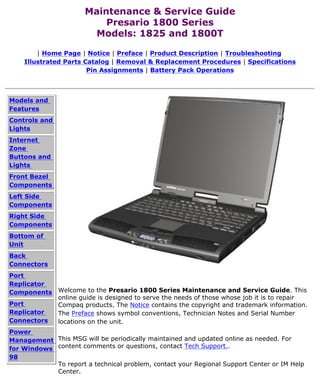
Components Welcome to the Presario 1800 Series Maintenance and Service Guide. This
online guide is designed to serve the needs of those whose job it is to repair
Port Compaq products. The Notice contains the copyright and trademark information.
Replicator The Preface shows symbol conventions, Technician Notes and Serial Number
Connectors locations on the unit.
Power
Management This MSG will be periodically maintained and updated online as needed. For
for Windows content comments or questions, contact Tech Support..
98
To report a technical problem, contact your Regional Support Center or IM Help
Center.
2. Maintenance & Service Guide
Presario 1800 Series
Models: 1825 and 1800T
| Home Page | Notice | Preface | Product Description |
Troubleshooting
Illustrated Parts Catalog | Removal & Replacement Procedures |
Specifications
Pin Assignments | Battery Pack Operations
Notice
The information in this guide is subject to change without notice.
COMPAQ COMPUTER CORPORATION SHALL NOT BE LIABLE FOR TECHNICAL OR
EDITORIAL ERRORS OR OMISSIONS CONTAINED HEREIN, NOR FOR INCIDENTAL
OR CONSEQUENTIAL DAMAGES RESULTING FROM THE FURNISHING,
PERFORMANCE, OR USE OF THIS MATERIAL.
This guide contains information protected by copyright. No part of this guide may be
photocopied or reproduced in any form without prior written consent from Compaq
Computer Corporation.
1999 Compaq Computer Corporation.
All rights reserved. Printed in the U.S.A.
Compaq, Presario 1800 Series Registered U. S. Patent and Trademark Office.
Microsoft, MS-DOS, and Windows are registered trademarks of Microsoft Corporation.
Windows 98 is a trademark of Microsoft Corporation.
The software described in this guide is furnished under a license agreement or
nondisclosure agreement. The software may be used or copied only in accordance with
the terms of the agreement.
Product names mentioned herein may be trademarks and/or registered trademarks of
their respective companies.
Maintenance and Service Guide
Compaq Presario 1800 Series Portable Computer
First Edition (August 1999)
Compaq Computer Corporation
3. Maintenance & Service Guide
Presario 1800 Series
Models: 1825 and 1800T
| Home Page | Notice | Preface | Product Description | Troubleshooting
Illustrated Parts Catalog | Removal & Replacement Procedures | Specifications
Pin Assignments | Battery Pack Operations
Preface
This Maintenance and Service Guide is a troubleshooting guide that can be used for reference when
servicing the Compaq Presario 1800 Series Portable Computers.
Compaq Computer Corporation reserves the right to make changes to the Compaq Presario 1800
Series Portable Computers without notice.
Symbols
The following words and symbols mark special messages throughout this guide.
WARNING: Text set off in this manner indicates that failure to follow directions in the
warning could result in bodily harm or loss of life.
CAUTION: Text set off in this manner indicates that failure to follow directions could result in
damage to equipment or loss of data.
IMPORTANT: Text set off in this manner presents clarifying information or specific instructions.
Text set off in this manner presents commentary, sidelights, or interesting points of
NOTE:
information.
Technician Notes
WARNING: Only authorized technicians trained by Compaq should repair this equipment. All
troubleshooting and repair procedures are detailed to allow only subassembly/module level
repair. Because of the complexity of the individual boards and subassemblies, the user should
not attempt to make repairs at the component level or to make modifications to any printed
circuit board. Improper repairs can create a safety hazard. Any indications of component
replacement or printed circuit board modifications may void any warranty
Serial Number
When requesting information or ordering spare parts, the computer serial number should be
provided to Compaq. The serial number is located on the bottom of the computer.
Locating Additional Information
The following documentation is available to support this product:
q Compaq Presario 1800 Series Portable Computer documentation set
q Introducing Windows 98 Guide
q Service Training Guides
q Compaq Service Advisories and Bulletins
q Compaq QuickFind
q Compaq Service Quick Reference Guide
Top of Page
4. Maintenance & Service Guide
Presario 1800 Series
Models: 1825 and 1800T
| Home Page | Notice | Preface | Product Description | Troubleshooting
Illustrated Parts Catalog | Removal & Replacement Procedures |
Specifications
Pin Assignments | Battery Pack Operations
Product Description
Models and Compaq
Presario
Features
1800 Series
Controls and Portable
Lights Computers
are a new
Internet generation
Zone of
Buttons and multimedia
Lights portable
computers
Front Bezel with a thin
Components and light-
Left Side weight
design,
Components
outstanding
Right Side audio and
Components video,
advanced
Bottom of core
Unit features,
and
Back
attractive
Connectors styling.
Port
Replicator The 1800T
Components Series
allows
Port configure-to-
Replicator order (CTO)
Connectors accessibility,
providing a
Power
range of
Management outstanding
for Windows and
98 innovative
features and
components.
5. Maintenance & Service Guide
Presario 1800 Series
Models: 1825 and 1800T
| Home Page | Notice | Preface | Product Description | Troubleshooting
Illustrated Parts Catalog | Removal & Replacement Procedures | Specifications
Pin Assignments | Battery Pack Operations
Troubleshooting
Preliminary
Steps This section covers troubleshooting information for the Compaq Presario 1800 Series
Clearing the Portable Computers. The basic steps in troubleshooting include:
Power-On
Password 1. Follow the Preliminary Steps.
Power-On Self
2. Run the Power-On Self-Test (POST).
Test (POST)
Compaq 3. Follow the recommended actions described in the diagnostic tables if you
Diagnostics are unable to run POST or if POST displays an error message.
Diagnostic Error
Codes When following the recommended actions in the Sections on POST and
Diagnostic Error Codes perform them in the order listed. Rerun POST after
Troubleshooting
each recommended action until the problem is solved and no error message
Without
occurs. Once the problem is solved, do not complete the remaining
Diagnostics recommended actions.
Solving Minor
Problems If the problem is intermittent, check the computer several times to
NOTE:
verify that the problem is solved.
Contacting
Compaq
Support
6. Maintenance & Service Guide
Presario 1800 Series
Models: 1825 and 1800T
| Home Page | Notice | Preface | Product Description |
Troubleshooting
Illustrated Parts Catalog | Removal & Replacement Procedures |
Specifications
Pin Assignments | Battery Pack Operations
Illustrated Parts Catalog
System Unit This section provides a breakdown of spare parts and
Boards
identifies the spare part ordering number associated with
each item for Compaq Presario 1800 Series Portable
Display
Computers.
Assembly
Mass Storage
Devices
Miscellaneous
Cable Kit
Miscellaneous
Hardware Kit
Miscellaneous
Plastics Kit
Miscellaneous
Parts
Documentation
and Software
7. Maintenance & Service Guide
Presario 1800 Series
Models: 1825 and 1800T
| Home Page | Notice | Preface | Product Description | Troubleshooting
Illustrated Parts Catalog | Removal & Replacement Procedures | Specifications
Pin Assignments | Battery Pack Operations
Removal and Replacement Procedures
This section explains the removal and replacement procedures for the computer.
Serial Number Location
Removal
Sequence
Electrostatic
Discharge
Service
Considerations
Cables and
Connectors
Preparing the
Computer for
Disassembly
Battery Pack
Palmrest
Cover with
TouchPad
Keyboard
Status Panel Report the computer serial number to Compaq when requesting information or
ordering spare parts. The serial number is located on the underside of the
Internet
computer.
Button Board
Heatspreader
Network
Interface Card
Modem
Hard Drive
DisqPlay
Module
Processor
DVD or
CD Drive
Display Panel
Assembly
Upper CPU
Cover
Fan Assembly
Diskette Drive
Battery
Charger Board
Speaker
Assembly
System Board
Memory
Module
8. Maintenance & Service Guide
Presario 1800 Series
Models: 1825 and 1800T
| Home Page | Notice | Preface | Product Description | Troubleshooting
Illustrated Parts Catalog | Removal & Replacement Procedures | Specifications
Pin Assignments | Battery Pack Operations
Specifications
This section covers the following specifications of Compaq Presario 1800 Series Portable
Computers:
q Physical and Environmental
q System Interrupts
q System DMA
q System I/O Address
q System Memory Catalog
q Display
q Memory Expansion
q Diskette or LS120 Drive
q Hard Drive
q DVD or CD drive
q Battery Pack
Physical and Environmental
Computer Specifications
U.S. Metric
Dimensions
Height 1.65 in 4.20 cm
Depth 13.00 in 33.00 cm
Width 10.99 in 27.90 cm
Weight 7.9 lbs 3.58 kg
Stand-Alone (Battery Pack) Power
Requirements Li-ion 3.2 mAh
Nominal Operating W @ 14.8 V
Maximum Average W @ 14.8 V
Peak Operating W @ 14.8 V
AC Power Requirements
Operating Voltage 100-240 V
Operating Current 0.8/0.4 A RMS
Operating Frequency 47-63 Hz
Maximum Transient Meets IEC 801-4 and IEC801-5
1kV for 50 ns
Temperature
Operating 50° to 95 °F 10° to 35 °C
Nonoperating -4° to 140 °F -20° to 60 °C
Relative Humidity (noncondensing)
Operating 90% 10% to 90%
Nonoperating (tw = 38.7°C max) 5% to 95% 5% to 95%
Altitude
Operating 0 to 10,000 ft 0 to 3.05 km
Nonoperating 0 to 30,000 ft 0 to 9.14 km
Shock
Operating 10 G, 11 ms, half sine
Non operating 240 G, 2 ms, half sine
Vibration
Operating 0.5 G
Nonoperating 1.5 G
NOTE: Applicable product safety standards specify thermal limits for plastic surfaces. Compaq Explorer
Series Portable Computers operate well within this range of temperatures.
Top of Page
System Interrupts
System Interrupts
Hardware IRQ System Function
IRQ0 System timer
IRQ1 Standard 101/102-key or Microsoft Natural Keyboard
IRQ2 Programmable interrupt controller
IRQ3 Lucent 56K V.90 PCI DF Modem
IRQ4 Communications Port (COM1)
IRQ5 ESS SOLO-1 PCI AudioDrive
IRQ5 RAGE LT PRO AGP 2X (English)
IRQ6 Standard Floppy Disk Controller
IRQ7 Printer Port (LPT1)
IRQ8 System CMOS/real time clock
IRQ9 Available
IRQ10 Available
IRQ11 Intel 21143/2 based 10/100 mbps Ethernet Controller
IRQ11 Texas Instruments PCI-1211 CardBus Controller
IRQ11 Intel 82371AB/EB PCI to USB Universal Host Controller
IRQ12 Synaptics PS/2 TouchPad
IRQ13 Numeric Data Processor
IRQ14 Intel 82371AB/EB PCI Bus Master Primary IDE Controller
IRQ15 Intel 82371AB/EB PCI Bus Master Secondary IDE Controller
Top of Page
System DMA
System DMA
Hardware DMA System Function
DMA 1 ESS SOLO-1 DOS Emulation
DMA 2 Standard Floppy Disk Controller
DMA 3 ECP Printer Port (LPT1)
DMA 4 Direct memory access controller
Top of Page
System I/O Address
System I/O Address
I/O Address (Hex) System Function (Shipping Configuration)
0000h-000Fh Direct memory access controller
0020h-0021h Programmable interrupt Controller`
0040h-0043h System timer
Standard 101/102-Key or Microsoft Natural
0060h-0060h
Keyboard
0061h-0061h System speaker
Standard 101/102-Key or Microsoft Natural
0064h-0064h
Keyboard
0070h-0071h System CMOS/real time clock
0072h-0073h Motherboard resources
0080h-0080h Motherboard resources
0081h-008Fh Direct memory controller
00A0h-00A1h Programmable interrupt controller
00C0h-00DFh Direct memory access Controller
00ECh-00EFh Motherboard resources
00F0h-00FFh Numeric data processor
Intel 82371AB/EB PCI Bus Master IDE
0170h-0177h
controller
0170h-0177h Secondary IDE controller (dual fifo)
Intel 82371AB/EB PCI Bus Master IDE
01F0h-01F7h
controller
01F0h-01F7h Primary IDE controller (dual fifo)
0200h-0203h Gameport Joystick
0220h-022Fh ESS SOLO-1 DOS Emulation
0330h-0331h ESS SOLO-1 DOS Emulation
Intel 82371AB/EB PCI Bus Master IDE
0376h-0376h
Controller
0376h-0376h Secondary IDE controller (dual fifo)
0378h-037Fh ECP Printer Port (LPT1)
0388h-038Bh ESS SOLO-1 DOS Emulation
03B0h-03BBh RAGE LT PRO AGP 2X (English)
03C0h-03Dfh RAGE LT PRO AGP 2X (English)
03E0h-03E1h Motherboard resources
03F0h-03F5h Standard Floppy Disk Controller
Intel 82371AB/EB PCI Bus Master IDE
03F6h-03F6h
Controller
03F6h-03F6h Primary IDE controller (dual fifo)
03F7h-03F7h Standard Floppy Disk Controller
03F8h-03FFh Communications Port (COM1)
04D0h-04D1h Motherboard resource
0CF8h-0CFFh PCI bus
2180h-218Fh Motherboard resources
8000h-803Fh Motherboard resources
Intel 82443BX Pentium ® II Processor to AGP
E000h-EFFFh
controller
E800h-E8FFh RAGE LT PRO AGP 2X (English)
F4D8h-F4DBh ESS SOLO-1 PCI AudioDrive
F4DCh-F4DFh ESS SOLO-1 PCI AudioDrive
F4E0h-F4Efh ESS SOLO-1 PCI AudioDrive
F4F0h-F4FFh ESS SOLO-1 PCI AudioDrive
F800h-F8FFh Lucent 56K V.90 PCI DF Modem
Intel 21143/2 based 10/100 mbps Ethernet
FC00h-FC7Fh
Controller
FC88h-FC8Fh Lucent 56K V.90 PCI DF Modem
FC90h-FC97h Primary IDE controller (dual fifo)
Intel 822371AB/EB PCI Bus Master IDE
FC90h-FC9Fh
Controller
FC98h-FC9F Secondary IDE controller (dual fifo)
Intel 82371AB/EB PCI to USB Universal Host
FCA0h-FCBFh
Controller
FCC0h-FCFFh ESS SOLO-1 PCI AudioDrive
Top of Page
System Memory Catalog
System Memory Catalog
Memory Address System Function
00000000h-0009FFFFh System board extension for PnP BIOS
000A0000h-000AFFFFh RAGE LT PRO AGP 2X (English)
000B0000h-000BFFFFh RAGE LT PRO AGP 2X (English)
000C0000h-000CBFFFh RAGE LT PRO AGP 2X (English)
000E0000h-000E7FFFh Motherboard resources
000E8000h-000FFFFFh System board extension for PnP BIOS
00100000h-03FFFFFFh System board extension for PnP BIOS
08000000h-08000FFFh Texas Instruments PCI-1211 CardBus Controller
F8000000h-FBFFFFFFh Intel 82443BX Pentium ® ll Processor to PCI
bridge
FD000000h-FDFFFFFFh RAGE LT PRO AGP2X (English)
FD000000h-FECFFFFFh Intel 82443BX Pentium ® ll Processor to AGP
controller
FE000000h-FE01FFFFh RAGE LT PRO AGP 2X (English)
FECFE000h-FECFFFFh RAGE LT PRO AGP 2X (English)
FEDFF800h-FEDFFBFFh Intel 21143/2 based 10/100 mbps Ethernet
Controller
FEDFFC00h-FEDFFCFFh Lucent 56K V.90 PCI DF Modem
FFF80000h-FFFFFFFFh Motherboard resources
Display
15.0" (Diagonal) TFT Display with LVDS
U.S. Metric
Dimensions
Height 9.48 in 24.05 cm
Width 12.43 in 31.55 cm
Display Dimensions
Height 8.99 in 22.81 cm
Width 11.98 in 30.41 cm
Depth Information not available Information not
available
Weight 24.36 oz 690 gm
Contrast Ratio 150:1 mini
Brightness 120 cd/mm^3
Total Power Consumption Information not available
Top of Page
14.1" (Diagonal) TFT Display with LVDS
U.S. Metric
Dimensions
Height 8.92 in 22.65 cm
Width 11.76 in 29.85 cm
Display Dimensions
Height 8.44 in 21.43 cm
Width 11.26 in 28.57 cm
Depth Information not Information not
available available
Weight 19.94 oz 565 gm
Contrast Ratio 150:1 mini
Brightness 120 cd/mm^3
Total Power Consumption Information not available
Top of Page
Memory Expansion
Memory Expansion
System Memory Expansion Board Total Memory
Memory
64-MB 64-MB
64-MB 32-MB 96-MB
64-MB 64-MB 128-MB
64-MB 128-MB 192-MB
Diskette or LS120 Drive
Diskette Drive LS120 Drive
Capacity per Diskette (High/Low) 1.44 MB/720KB 120 MB
Diskette Size 3.5" 3.5"
Number of LED Indicators (Read/Write) 0 1
Number of Drives Supported 1 1
Drive Rotation (rpm) 300 720
Transfer Rate (Kbps) 500 5458
Bytes per Sector 512 512
Sectors per Track (High/Low) 18/9
Tracks per Side (High/Low) 80
Access Times
Track-to-Track (ms) 3 20
Average (ms) 94 112
Setting Time (ms) 15 800
Latency Average (ms) 100 41.67
Cylinders (High/Low) 80 1736
Number of Read/Write Heads 2 2
Top of Page
Hard Drive
Hard Drive
4.8-GB 6.4-GB 10.0-GB 18.0-GB
Capacity Per Drive 4.8-GB 6.4-GB 10.0-GB 18.0-GB
Drive Type
Logical Configuration
Cylinders 11648 8647 11968 16383
Heads 3 4 6 6
Sectors per track 190/330 190/330 190/330 Not available
Bytes per sector 512 512 512 512
Seek Times
(Typical, Including settling in ms)
Single track 4 4 4
14 14 14 2.5 (Read)
Average
24 24 24 12 (Read)
Full stroke
23 (Read)
Transfer Rate At Interface 33.3 MB/s 33.3 MB/s 33.3 MB/s 33.3 MB/s
Top of Page
CD/DVD Drive
CD/DVD Drive
4x DVD 6x DVD 24x CD-ROM
Dimensions 128 x 129 x 12.7 mm 128 x 129 x 12.7mm 128 x 129 x 12.7 mm
Weight 0.27 kg 0.28 kg <0.27 kg
Rotational Speed 2300 rpm 3450 rpm 4225 rpm
Typical Transfer Rate 5400 KB/s 8100 KB/s 3600 KB/s
Sustained Data Transfer
Rate
Access Time 140 ms 140 ms 120 ms
Average Random Access
Time
Spin Up time 3.8 s <15 s 2.7 s
Data Buffer Capacity 128 KB 512 KB 128 KB
Top of Page
Battery Pack
Battery Pack
Lithium Ion (Li ion) *
Dimensions
Height 0.8 in (20.3 mm)
Length 5.7 in (145 mm)
Width 3.1 in (78.7 mm)
Weight 0.90 lb (408.2 g)
Battery Pack Operating Time 2 hr 30 min*
Energy
Nominal Open Circuit Voltage 14.4 V
Capacity 3200 mAH
Power 46.1 WH
Environmental Requirements
Operating Temperature 32° F (0-50° C)
Non-operating Temperature -20° C -60° C
Charging Temperature 5° C-45° C
*The battery operating time changes depending on your power management settings, system
components, options, and applications you use.
Top of Page
9. Maintenance & Service Guide
Presario 1800 Series
Models: 1825 and 1800T
| Home Page | Notice | Preface | Product Description | Troubleshooting
Illustrated Parts Catalog | Removal & Replacement Procedures | Specifications
Pin Assignments | Battery Pack Operations
Connector Pin Assignments
This section provides connector pin assignment tables for Compaq Presario 1800 Series Portable
Computers. For more information on connectors, refer to the sections on Back Connectors and Port
Replicator Connectors.
NOTE: The signals in all tables of this appendix are considered active high unless otherwise
indicated by an asterisk (*).
Parallel Connector
Pin Signal Pin Signal
1 Strobe* 10 Acknowledge*
2 Data Bit 0 11 Busy
3 Data Bit 1 12 Paper Out
4 Data Bit 2 13 Select
5 Data Bit 3 14 Auto Linefeed*
6 Data Bit 4 15 Error*
7 Data Bit 5 16 Initialize Printer*
8 Data Bit 6 17 Select In*
9 Data Bit 7 18-25 Signal Ground
* = Active low
Top of Page
Serial Connector
Connector Pin Signal
1 Carrier Detect
2 Receive Data
3 Transmit Data
4 Data Terminal Ready
5 Signal Ground
6 Data Set Ready
7 Ready to Send
8 Clear to Send
9 Ring Indicator
Keyboard/Mouse
Connector Pin Signal
1 Data 1
2 Data 2
3 Ground
4 +5 V
5 Clock 1
6 Clock 2
Top of Page
External VGA Monitor
Connector Pin Signal
1 Red Analog
2 Green Analog
3 Blue Analog
4 Not connected
5 Ground
6 Ground Analog
7 Ground Analog
8 Ground Analog
9 +5V
10 Ground
11 Monitor Detect
12 DDC2B Data
13 Horizontal Sync
14 Vertical Sync
15 DDC2B Clock
Top of Page
Universal Serial Bus
Connector Pin Signal
1 +5V
Data -
2
Data +
3
Ground
4
Top of Page
Modem
Connector Pin Signal
1 Unused
2 Tip
3 Ring
4 Unused
5 Unused
6 Unused
Top of Page
TV Out
Connector Pin Signal
1 Ground
2 Composite
3 Ground
Top of Page
Game Port
Connector Pin Signal
1 +5V
2 SWA
3 RBTA
4 GND
5 GND
6 RBTB
7 SWB
8 +5V
9 +5V
10 SWC
11 RBTC
12 RMSO
13 RBTD
14 SWD
15 RMSI
Top of Page
S Video
Connector Pin Signal
1 Ground
2 Ground
3 SYR
4 SCG
Top of Page
Port Replicator Connector
Pin Signal Pin Signal Pin Signal Pin Signal
1 Adapter Power 21 Serial Port CTS 41 Not Connected 61 Switch C
2 Adapter Power 22 Serial Port DCD 42 Power Cycle 62 Switch D
3 Adapter Power 23 Serial Port DSR 43 Keyboard Clock 63 MIDI Input
4 Adapter Power 24 Serial Port TXD 44 Keyboard Data 64 MIDI Output
5 Adapter Power 25 Serial Port RTS 45 Mouse Clock 65 Not Connected
6 Adapter Power 26 Monitor DDC 46 Mouse Data 66 USB Power
7 Not Connected 27 Monitor DDC 47 Lp Select 67 USB Power
8 Printer Data 0 28 Monitor Indicator 48 Lp Paper End 68 USB Power
9 Printer Data 1 29 V. SYNC 49 Lp Initialize 69 USB Power
10 Printer Data 2 30 Ground 50 Lp Busy 70 USB A-
11 Printer Data 3 31 H.SYNC 51 Lp Error 71 USB A+
12 Printer Data 4 32 Ground 52 Lp Acknowledge 72 USB B-
13 Printer Data 5 33 Blue 53 Lp AutoFeed 73 USB B+
14 Printer Data 6 34 Ground 54 Lp Strobe 74 5V
15 Printer Data 7 35 Green 55 Joystick Data A 75 5V
16 Lp Indicator 36 Ground 56 Joystick Data B 76 Not Connected
17 Port Replicator Dock 37 Red 57 Joystick Data C 77 S-Video SYR
Indicator
18 Serial Port RXD 38 Ground 58 Joystick Data D 78 Ground
19 Serial Port RI 39 Composite TV Out 59 Switch A 79 S-Video SCG
20 Serial Port DTR 40 Not Connected 60 Switch B 80 Ground
Top of Page
10. Maintenance & Service Guide
Presario 1800 Series
Models: 1825 and 1800T
| Home Page | Notice | Preface | Product Description | Troubleshooting
Illustrated Parts Catalog | Removal & Replacement Procedures | Specifications
Pin Assignments | Battery Pack Operations
Battery Pack Operations
This appendix covers the following information concerning battery pack operating time:
q Increasing battery pack operating time
q Conditioning a battery pack
q Disposing of a used battery pack
Increasing Battery Pack Operating Time
Battery pack operating time differs depending on several variables. To avoid unnecessary replacement, consider the
following variables when determining how long a charged battery pack should last:
q Power management settings
q Hardware configuration
q Software applications
q Installed options
q Display brightness
q Hard drive usage
q Changes in operating temperature
q Type and number of installed PC Cards
The power consumption requirements for PC Cards vary widely. Some cards drain the battery pack
NOTE:
very rapidly.
Battery pack operating time can be increased by as much as 50 percent by controlling the energy required by the computer
and the energy stored in the battery pack.
Minimizing the Energy Required
To minimize the energy required by the computer, follow these guidelines:
q Set the power conservation levels in the Power Management utility to Maximum.
q Customize the timeout value to work more efficiently with the applications. The length of battery life
depends on the values selected.
Maximizing the Energy Stored
To maximize the energy stored in the battery pack, follow these guidelines
q Condition the battery pack at least every 30 days to improve overall battery performance.
q Keep a battery pack in the computer when using it with AC power to supply the battery pack with a
constant trickle charge.
q Store the battery pack in a cool, dry place when not in use.
Top of Page
Conditioning a Battery Pack
CAUTION: To avoid a loss of data, ensure that all data is saved before discharging a battery pack.
To condition a battery pack, complete the following steps:
1. Plug in the AC adapter and allow the battery to charge until the battery charging status icon turns off. Your
battery gauge may show four bars (and Windows may report 100%) before the battery charging status icon
turns off. Do not unplug the AC adapter until the battery charging status icon disappears.
2. Unplug the AC adapter and allow the battery to drain until the computer reaches hibernation and turns itself
off. Do not plug in the AC adapter during this process or you will need to restart with Step 1. You
may use the computer while the battery is draining.
3. Plug in the AC adapter and begin using the computer.
The table below shows the approximate battery pack charge times.
Approximate Battery Charge Time
Computer On Line Off Line
Li ion Battery Pack 4.5 hours 2:50 hrs
Top of Page
Disposing of a Used Battery Pack
In the interest of safeguarding our environment. Compaq Computer Corporation recommends that nickel metal hydride
(NiMH) and lithium ion (Li ion) battery packs be recycled. Battery packs should be handled in accordance with country,
state, province, or local regulations.
CAUTION: Never attempt to open or service a battery pack. Opening a battery pack not only damages the
pack and makes it unusable, but also exposes potentially harmful battery components.
Top of Page
11. Maintenance & Service Guide
Presario 1800 Series
Models: 1825 and 1800T
| Home Page | Notice | Preface | Product Description |
Troubleshooting
Illustrated Parts Catalog | Removal & Replacement Procedures |
Specifications
Pin Assignments | Battery Pack Operations
Models and Features
Models and Compaq Presario 1800 Series Portable Computer Models
Features Model 1825
Controls and Display 15.0" TFT
Lights
Processor Pentium II/366-MHz w/256 Cache
Internet Hard Drive 6.4-GB
Zone
CD or DVD Drive 4x DVD Drive
Buttons and
Diskette Drive 3.5" Floppy Drive
Lights
Modem 56.0 Kbps Data/Fax with PCI
Front Bezel
Networking 10/100TX Integrated Ethernet
Components
Battery sLi ion
Left Side
System Memory 64 MB
Components
Right Side
Model 1800T CTO (Configure to Order)
Components
Bottom of
Display
Unit 14.1 " TFT
Back
Connectors
Processor
Port
Celeron 400-MHz w/128 Cache
Replicator
Components
Port
Replicator Hard Drive
Connectors 4.8 GB
Power
Management
for Windows CD or DVD Drive
98 24x CD-ROM
Diskette Drive
3.5" Floppy Drive
Modem 56.0 Kbps Data/Fax with PCI
Networking 10/100TX Integrated Ethernet
System Memory
64 MB
12. Maintenance & Service Guide
Presario 1800 Series
Models: 1825 and 1800T
| Home Page | Notice | Preface | Product Description |
Troubleshooting
Illustrated Parts Catalog | Removal & Replacement Procedures |
Specifications
Pin Assignments | Battery Pack Operations
Product Description
Models and Controls
Features and
Controls and Lights
Lights
Internet
1. Display
Zone
Release
Buttons and
Latch
Lights
2. Display
Front Bezel
3. Power
Components
(On/Off)
Left Side Button
Components 4.
Right Side Keyboard
Components 5. Touch
Pad
Bottom of
Unit 6.
Integrated
Back Speakers
Connectors 7. Touch
Port Pad
Replicator Button
(Left)
Components
8. Scroll
Port Up/Down
Replicator Button
Connectors
9. Touch
Power Pad
Management Button
for Windows (Right)
98 10. Model
Number
13. Maintenance & Service Guide
Presario 1800 Series
Models: 1825 and 1800T
| Home Page | Notice | Preface | Product Description | Troubleshooting
Illustrated Parts Catalog | Removal & Replacement Procedures |
Specifications
Pin Assignments | Battery Pack Operations
Product Description
Models and Internet Zone
Features Buttons and
Controls and Lights
Lights
Internet
1. AC Adapter
Zone
Light
Buttons and
Lights 2. Cap Lock Light
Front Bezel 3. Instant
Components Internet Access
Button
Left Side
4. Instant E-Mail
Components
Button
Right Side 5. My Presario
Components Instant Access
Bottom of Button
Unit 6. Power Button
Back 7. Instant Search
Connectors Button
8. Online
Port
Marketplace
Replicator Button (US/Puerto
Components Rico), Instant
Port Answer Button
(countries outside
Replicator
the US)
Connectors
9. Retail Central
Power Button (US/Puerto
Management Rico), Instant E-
for Windows Commerce Button
98 (countries outside
the US)
10. Num Lock
Light
11. Scroll Lock
Light
14. Maintenance & Service Guide
Presario 1800 Series
Models: 1825 and 1800T
| Home Page | Notice | Preface | Product Description | Troubleshooting
Illustrated Parts Catalog | Removal & Replacement Procedures |
Specifications
Pin Assignments | Battery Pack Operations
Product Description
Models and Front Bezel
Features Components
Controls and
Lights
1. Previous
Internet Track Button
Zone 2. Next Track
Buttons and Button
Lights 3. Sleep Status
Front Bezel Icon
Components 4. Power Status
Left Side Icon
Components 5. Battery
Charging Status
Right Side
Icon
Components
6. DisqPlay
Bottom of Status Icon
Unit
7. Battery
Back Gauge
Connectors 8. DisqPlay
Port On/Off Button
Replicator 9. Volume
Components Down Button
Port 10.Volume Up
Button
Replicator
Connectors 11. Play/Pause
Button
Power
12. Stop Button
Management
for Windows
98
15. Maintenance & Service Guide
Presario 1800 Series
Models: 1825 and 1800T
| Home Page | Notice | Preface | Product Description | Troubleshooting
Illustrated Parts Catalog | Removal & Replacement Procedures |
Specifications
Pin Assignments | Battery Pack Operations
Product Description
Models and Left Side
Features Components
Controls and with
Lights
Diskette
Internet
Zone
Drive
Buttons and
Lights 1. Security Slot
Front Bezel 2. CD or DVD
Components Drive
Left Side 3. CD or DVD
Components Drive Eject Button
Right Side 4. CD or DVD
Drive Manual Eject
Components
Hole
Bottom of 5. Diskette Drive
Unit
6. Diskette Drive
Back Eject Button
Connectors
Left Side
Port Components with
Replicator LS120 Drive
Components
Port
Replicator
Connectors
Power
Management
for Windows
98
16. Maintenance & Service Guide
Presario 1800 Series
Models: 1825 and 1800T
| Home Page | Notice | Preface | Product Description | Troubleshooting
Illustrated Parts Catalog | Removal & Replacement Procedures |
Specifications
Pin Assignments | Battery Pack Operations
Product Description
Left Side Components
with LS120 Drive
1. Security Slot
2. CD or DVD Drive
3. CD or DVD Drive Eject
Button
4. CD or DVD Drive Manual
Eject Hole
5. LS120 Drive
6. LS120 Drive Eject
Button
7. LS120 Drive Manual
Eject Hole
Back to Left Side Components with
Diskette Drive
17. Maintenance & Service Guide
Presario 1800 Series
Models: 1825 and 1800T
| Home Page | Notice | Preface | Product Description | Troubleshooting
Illustrated Parts Catalog | Removal & Replacement Procedures | Specifications
Pin Assignments | Battery Pack Operations
Product Description
Models and Right Side
Features Components
Controls and
Lights
1. Battery
Internet Compartment
Zone 2. PC Card Eject
Buttons and Button
Lights 3. PC Card Slot
Front Bezel 4. Headphone
Components Jack
Left Side 5. Microphone
Components Jack
Right Side 6. Modem Port
Components 7. Ethernet Port
Bottom of
Unit
Back
Connectors
Port
Replicator
Components
Port
Replicator
Connectors
Power
Management
for Windows
98
18. Maintenance & Service Guide
Presario 1800 Series
Models: 1825 and 1800T
| Home Page | Notice | Preface | Product Description | Troubleshooting
Illustrated Parts Catalog | Removal & Replacement Procedures | Specifications
Pin Assignments | Battery Pack Operations
Product Description
Models and Bottom of Unit
Features
Controls and 1. Stand Feet
Lights 2. Serial Number
Internet 3. Memory
Zone Compartment Door
Buttons and
Lights
Front Bezel
Components
Left Side
Components
Right Side
Components
Bottom of
Unit
Back
Connectors
Port
Replicator
Components
Port
Replicator
Connectors
Power
Management
for Windows
98
19. Maintenance & Service Guide
Presario 1800 Series
Models: 1825 and 1800T
| Home Page | Notice | Preface | Product Description | Troubleshooting
Illustrated Parts Catalog | Removal & Replacement Procedures | Specifications
Pin Assignments | Battery Pack Operations
Product Description
Models and Back
Features Connectors
Controls and
Lights
1. Keyboard/Mouse
Internet Port
Zone 2. AC
Buttons and Adapter Connector
Lights 3. Parallel Port
Front Bezel 4. Port Replicator
Components Connector
Left Side 5. Fan Vent
Components 6. TV Out Connector
Right Side 7. External Monitor
Components Port
Bottom of 8. Serial Port
Unit 9. Universal Serial
Bus Port
Back
Connectors
Port
Replicator
Components
Port
Replicator
Connectors
Power
Management
for Windows
98
20. Maintenance & Service Guide
Presario 1800 Series
Models: 1825 and 1800T
| Home Page | Notice | Preface | Product Description | Troubleshooting
Illustrated Parts Catalog | Removal & Replacement Procedures | Specifications
Pin Assignments | Battery Pack Operations
Product Description
Models and Port
Features Replicator
Controls and Components
Lights
Internet
1. Port
Zone Replicator
Buttons and Interface
Lights Connector
Front Bezel 2. Port
Components Replicator Guide
Posts
Left Side
Components
Right Side
Components
Bottom of
Unit
Back
Connectors
Port
Replicator
Components
Port
Replicator
Connectors
Power
Management
for Windows
98
21. Maintenance & Service Guide
Presario 1800 Series
Models: 1825 and 1800T
| Home Page | Notice | Preface | Product Description | Troubleshooting
Illustrated Parts Catalog | Removal & Replacement Procedures |
Specifications
Pin Assignments | Battery Pack Operations
Product Description
Models and Port
Features Replicator
Controls and Back
Lights
Connectors
Internet
Zone
Buttons and 1. Universal Serial
Bus Port
Lights
2. Universal Serial
Front Bezel Bus Port
Components
3. Power (AC
Left Side Adapter) Connector
Components 4. Keyboard/Mouse
Right Side Port
Components 5. Keyboard/Mouse
Port
Bottom of
Unit 6. Parallel Port
Back 7. Game Port
Connectors 8. Serial Port
Port 9. External Monitor
Replicator Port
Components 10. S Video
Port 11. (Composite)
Replicator TV Out
Connectors
Power
Management
for Windows
98
22. Maintenance & Service Guide
Presario 1800 Series
Models: 1825 and 1800T
| Home Page | Notice | Preface | Product Description | Troubleshooting
Illustrated Parts Catalog | Removal & Replacement Procedures | Specifications
Pin Assignments | Battery Pack Operations
Power Management for Windows 98
The following power management features are available for conserving AC power and extending battery operating time:
q Power Management Settings
q Hibernation Mode
q Sleep Mode
q Battery Operating Time
q Rebooting After a Lockup
q Recovering From a Loss of Electrical Power
q Servicing the Computer - Full Off Mode
Power Management Settings
Differing patterns of computer use determine the level of power management. These different power management levels
can be activated based on the amount of time passed since the last system activity. System activity examples include
keyboard or mouse movement, DVD/CD playback (while under program control that monitors Sleep), and modem use.
Select different power settings or schemes through Power Management.The optional settings are Home/Office Desk,
Portable/Laptop, and Always On. Change the following settings from the default settings:
q when the computer goes into Sleep (Standby) mode
q when the screen times out and goes blank
q when the hard drive goes into low power mode.
Each of these system components sleeps after the selected or default periods of inactivity. (The setting for hard drive must
be less than or equal to the setting for System.)
IMPORTANT: If the computer is on a network, Compaq recommends System Standby be set to Never.
There are five categories of power management settings under the Control Panel. The default setting for each feature is
listed below in the tables.
Power Management Properties
Always on Plugged in Running on Batteries
System Standby Never 5 minutes
Turn OFF Monitor 15 minutes 2 minutes
Turn OFF Hard Disks 1 hour 3 minutes
Portable/Laptop Plugged in Running on Batteries
System Standby Never 15 minutes
Turn OFF Monitor 3 hours Never
Turn OFF Hard Disks 15 minutes 10 minutes
Home/Office Desk Plugged in Running on Batteries
System Standby 20 minutes 1 minute
Turn OFF Monitor 15 minutes 2 minutes
Turn OFF Hard Disks 30 minutes 10 minutes
CAUTION: The settings on the Alarms tab have been preset for the computer to run at
its best. Changing any of these settings could cause the computer to function improperly.
It is recommended that these settings be left at their default values.
Power Management Properties
Alarms:
Low Battery Alarm: 10%
Critical Battery Alarm 0%
Alarm Actions: Notification: Text
Power Mode: No Action
Compaq Presario 1800 Series Computers have two levels of power management: Hibernation and Sleep.
Hibernation mode occurs by pressing the Power button once. The computer saves the contents of the computer memory
to the hard drive. This is followed by the computer turning off.
Sleep mode is a low-power mode, also referred to as Standby mode. It occurs by pressing the Fn+F4 function key or by
clicking the Start button, then Shutdown, then Standby.
CAUTION: While in Sleep mode, the computer will maintain system information and open
files. Unsaved information will be lost if the computer is turned off prior to system wake-
up, or if a power loss occurs while using the AC adapter.
The following table shows the conditions and indicators for getting in and out of the various power management modes,
Sleep, Hibernation, and Off.
Hibernation and Sleep Functions
Mode To Initiate To End Indicators
Manual - Fn+F4 key Flashing Power light*
combination or click the Start
button on the Windows Taskbar,
Press any key.
then point to Shutdown, then
*Moon icon appears on status display
click Standby.
(1800 Series only)
Sleep Time-Out Default - 15 minutes
if using battery power.
Computer will not automatically
enter Sleep mode if on AC
power.
Manual - Press Power Button Power light is off, screen is blank*
once
*Power icon does not appear on status
Hibernate Press Power display (1800 Series only)
Button once
Time-Out Default - If your
battery is low or after 1 hour of
Sleep. Computer will not
automatically enter Hibernation
mode if on AC power.
Standard - Perform normal
Windows shutdown using the
Start button on the Windows
Off Press Power No Power light (or icon), screen is blank.
Taskbar.
Button once
Manual* - Press and hold down
the Power button for 4 seconds.
*The Manual shutdown mode is
not recommended unless the
Standard shutdown mode does
not work.
Hibernation Mode
Hibernation helps conserve battery life and protect the data. Hibernation can be a routine power-saving event or the result
of a low battery. As the computer enters Hibernation, it automatically saves the content of the computer memory to the
hard drive before it turns off.
The computer will automatically enter Hibernation mode when the battery has little power left or when the computer
(operating on battery power) has been in Sleep mode for more than one hour. Activate Hibernation mode by pressing the
Power button once.
To restart the computer, press the Power button once. When the computer enters or wakes from Hibernation mode, it
displays a Progress window.
Top of Page
Sleep Mode
Selecting Sleep mode instead of turning off the computer when finished allows the computer to wake up faster than turning
it completely off and saves power over the active (On) mode.
Activate Sleep mode by pressing Fn+F4. Or, click Start, select the Shut Down option, and click Standby.
Servicing the Computer - Full Off Mode
The computer must be turned off completely when installing or replacing components in the system. Follow the instructions
above for properly putting the computer into Off mode, unplug from the outlet, and remove the battery (see battery
section for instruction on removing battery).
Top of Page
Rebooting After a Lockup
To reboot the computer (as if from a cold start), when the keyboard is frozen or the screen is locked, press and hold down
the Power button for at least four seconds, which will cause a manual shutdown. Then, restart it with a single press of the
Power button. If it still does not recover, press the Power button and hold for four seconds to shut it down, then remove
the battery or unplug the AC power for at least 30 seconds. Reinsert the battery or reconnect AC power and press the
Power button once to reboot.
Top of Page
Recovering From a Loss of Electrical Power
Loss of electrical power will cause the Internet PC to automatically turn off. This may cause loss of data because the
Microsoft Windows operating system is not able to properly close all files and programs.
Loss of power may be caused by one of the following:
q Electrical power service is interrupted.
q The power cord is accidentally disconnected.
If power surges or sags, the display and status lights may flicker, and the computer may automatically restart. If an
improper shutdown occurs, ScanDisk, a Microsoft Windows utility program, will automatically run once power is restored.
ScanDisk will determine if the improper shutdown caused any errors on the hard disk. These errors may occur if the
Microsoft Windows operating system was not able to properly close all files before the shutdown. If no errors are found, the
restart process will continue. If ScanDisk does detect errors, follow the instructions shown to continue the restart process.
Work that was not saved prior to the lockup may be lost.
Use of a surge suppressor, line conditioner, or uninterruptible power supply (UPS) may protect the computer from damage
caused by power surges or sags.
If a power failure occurs or the power cord disconnects while the computer is turned on, turn off the computer until normal
service has been restored. ScanDisk may run to check the hard disk for errors caused by the improper shutdown the next
time the computer turns on.
Top of Page
Battery Operating Time
Battery operating time is affected by variables such as the following:
q Power conservation settings
q Hardware configuration
q Software applications
q Installed options
q Display brightness
q Hard drive usage
q Changes in operating temperature
q Type and number of installed PC Cards
For more information on increasing battery pack operating time, conditioning the battery pack, and disposing of a used
battery pack, refer to the Battery Pack Operations.
Top of Page
23. Maintenance & Service Guide
Presario 1800 Series
Models: 1825 and 1800T
| Home Page | Notice | Preface | Product Description | Troubleshooting
Illustrated Parts Catalog | Removal & Replacement Procedures | Specifications
Pin Assignments | Battery Pack Operations
Preliminary Steps
Before running POST, complete the following preliminary steps:
1. If a power-on password has been established, type the password and press the
Enter key. If the password is not known, clear the password.
2. Run Computer Checkup.
3. Turn off the computer and its external devices.
4. Disconnect any external devices that you do not want to test. Do not disconnect
the printer if you want to test it or use it to log error messages.
If the problem only occurs when an external device is connected to the computer,
IMPORTANT: the problem may be related to the external device or its cable. Verify this by
running POST with and without the external device connected.
5. Install loopback plugs in the serial and parallel connectors if you would like to test
these ports.
6. Ensure the hard drive is installed in the computer.
7. Ensure that the battery pack is inserted in the computer and the computer is
connected to an external AC power source.
When the preliminary steps are completed, you are ready to run POST.
Return to Troubleshooting
24. Maintenance & Service Guide
Presario 1800 Series
Models: 1825 and 1800T
| Home Page | Notice | Preface | Product Description |
Troubleshooting
Illustrated Parts Catalog | Removal & Replacement Procedures |
Specifications
Pin Assignments | Battery Pack Operations
Troubleshooting
Clearing the Power-on Password
Clearing the power-on
password requires removing
all Setup attributes that are
programmed in the CMOS.
The RTC battery is located
on the system board directly
forward of the fan.
If the password is not known,
clear it by performing the
following steps:
1. Turn off the computer.
2. Disconnect the power cord.
3. Remove the battery pack.
4. Remove the palmrest cover
with touchpad.
5. Remove the keyboard.
6. Remove the heatspreader.
7. Slide the black switch
toward the front of the
computer to clear CMOS. Hold
the switch in the forward
position for at least 15
seconds to ensure that the
password is cleared. The
switch is located on the back
of the DVD or CD drive in the
middle of the system board.
8. Reassemble the computer.
9. Turn on the computer to
verify that the power-on
password has been cleared. If
it has not been cleared,
repeat Steps 1 through 9.
Return to Troubleshooting
25. Maintenance & Service Guide
Presario 1800 Series
Models: 1825 and 1800T
| Home Page | Notice | Preface | Product Description | Troubleshooting
Illustrated Parts Catalog | Removal & Replacement Procedures | Specifications
Pin Assignments | Battery Pack Operations
Power-On Self Test (POST)
Running POST
To run POST, complete these directions:
Turn off the computer, then turn on the computer. As soon as the Compaq logo appears press the ESC key to clear the logo
and display the POST messages as they occur.
If POST does not detect any errors, the computer will not beep. This indicates successful completion of the POST test. POST
has run successfully and boots from the hard drive (or from a bootable diskette if one is installed in the diskette drive).
If POST detects errors, the errors are indicated by screen and/or audible messages. Refer to "Power-On Self-Test (POST)
Codes" in the tables for a list of POST codes and their relevant descriptions.
If the system is not functioning well enough to run POST, or if the display is not functioning well enough to show
NOTE:
POST error messages, refer to the Troubleshooting tables.
Power-On Self-Test Messages
102-System Board Failure
Probable Cause Recommended Action
DMA, timers, etc. Replace the system board.
162-System Options Not Set
Probable Cause Recommended Action
Configuration incorrect Run Computer Setup.
CMOS reflects that an invalid Run Computer Setup.
configuration has been set.
RAM failure 1. Replace the memory modules.
2. Replace the system board.
Memory test data error 1. Replace the memory modules.
2. Replace the system board.
XX000YZZ RAM failure Replace the system board.
XX000YZZ 201-Memory Error
Probable Cause Recommended Action
1. Replace the memory modules.
2 Replace the system board.
301-Keyboard Error
Probable Cause Recommended Action
Keyboard failure 1. Ensure the keys are not depressed during POST.
2. Reconnect the keyboard with the computer off.
3. Replace the keyboard.
304-Keyboard or System Unit Error
Probable Cause Recommended Action
Keyboard or system board error 1. Replace the keyboard.
2. Replace the TouchPad or mouse.
3. Replace the system board.
601-Diskette Controller Error
Probable Cause Recommended Action
Mismatch in drive type or failure in the diskette 1. Run Computer Checkup (TEST).
controller
2. Check and/or replace cables.
3. Replace the system board.
605-Diskette Drive Error
Probable Cause Recommended Action
Mismatch in drive type Run Computer Setup.
1780-Primary Hard Drive 0 Failure
Probable Cause Recommended Action
Disk 0 failed to respond 1. Run Computer Checkup (TEST).
2. Replace the hard drive.
Hard drive format error 1. Run Computer Checkup (TEST).
2. Replace the hard drive.
1782-Hard Drive Controller
Probable Cause Recommended Action
Hard drive controller failure 1. Run Computer Setup.
2. Replace the hard drive.
Top of Page
Return to Troubleshooting
26. Maintenance & Service Guide
Presario 1800 Series
Models: 1825 and 1800T
| Home Page | Notice | Preface | Product Description | Troubleshooting
Illustrated Parts Catalog | Removal & Replacement Procedures |
Specifications
Pin Assignments | Battery Pack Operations
Compaq Diagnostics
Compaq Diagnostics is installed on the hard drive of the computer. Run the Diagnostics utilities when you
want to view or test system information and if you have installed or connected devices. If you run Compaq
Diagnostics from a diskette, ensure that it is version 10.11 or later.
The Diagnostics menu includes the following utilities:
s Computer Checkup (TEST)
s View System Information (INSPECT)
s Prepare Computer for a Compaq Service Call (RemotePaq)
If you have a problem you cannot solve, run the Diagnostics utilities before you call for support. Run
Computer Checkup and select to save the device list to a file and to print or to save the log of errors. Run
the View System Information (INSPECT) utility and select to print or to save that information. Have the
files or the printed information available when you call for support.
Computer Checkup (TEST)
Computer Checkup (TEST) determines whether the various computer components and devices are
recognized by the system and are functioning properly. You can display, print, or save the information
generated by Computer Checkup.
Follow these steps to run Computer Checkup:
1. Plug the computer into an external power source. (A low battery condition could interrupt the
program.)
2. Turn on the external devices that you want to test. Connect the printer if you want to print a log of
error messages.
3. Insert the Compaq Diagnostics diskette in drive A.
4. Turn on or restart the computer. The computer starts from drive A, and the Diagnostics Welcome
screen appears.
5. Press Enter to continue. The Diagnostics menu appears.
6. Select Computer Checkup from the Diagnostics menu. A Test Option menu appears.
7. Select View the Device List from the Test Option menu. A list of the installed Compaq devices
appears.
8. If the list of installed devices is correct, select OK. The Test Option menu appears.
NOTE: If the list is incorrect, ensure that any new devices are installed properly.
9. Select one of the following from the Test Option menu:
s Quick Check Diagnostics. Runs a quick, general test on each device with a minimal
number of prompts. If errors occur, they display when the testing is complete. You
cannot print or save the error messages.
s Automatic Diagnostics. Runs unattended, maximum testing of each device with
minimal prompts. You can choose how many times to run the tests, to stop on errors,
or to print or save a log of errors.
s Prompted Diagnostics. Allows maximum control over testing the devices. You can
choose attended or unattended testing, decide to stop on errors, or choose to print or
save a log of errors.
10. Follow the instructions on the screen as the devices are tested. When testing is complete, the Test
Option menu appears.
11. Exit the Test Option menu.
12. Exit the Diagnostics menu.
View System Information (INSPECT)
The View System Information (INSPECT) utility provides information about the computer and installed or
connected devices. You can display, print, or save the information.
Follow these steps to run View System Information (INSPECT) from the Compaq Diagnostics diskette:
1. Turn on the external devices that you want to test. Connect the printer if you want to print the
information.
2. Insert the Compaq Diagnostics diskette in drive A.
3. Turn on or restart the computer. The computer starts from drive A, and the Diagnostics Welcome
screen appears.
4. Press Enter to continue. The Diagnostics menu appears.
5. Select View System Information (INSPECT) from the Diagnostics menu.
6. Select the item you want to view from the following list:
System Memory
ROM Audio
Keyboard Operating system
System ports System files
System storage Windows files
Graphics
7. Follow the instructions on the screen to cycle through the screens, to return to the list and
choose another item, or to print the information.
Top of Page
Return to Troubleshooting
27. Maintenance & Service Guide
Presario 1800 Series
Models: 1825 and 1800T
| Home Page | Notice | Preface | Product Description |
Troubleshooting
Illustrated Parts Catalog | Removal & Replacement Procedures |
Specifications
Pin Assignments | Battery Pack Operations
Contacting Compaq Support
Obtain the following information before contacting Compaq Reseller Support:
q Product name
q Product serial number
q Purchase date
q Conditions under which the problem occurred
q Any error messages that have occurred
q Hardware configuration
q Type of printer connected
q Hardware/software being used
q Printed result of Computer Checkup (TEST)
q Printed copies of CONFIG.SYS and AUTOEXEC.BAT files, if possible
Shipping Preparation
To ship the computer, complete the following steps:
1. Back up the critical hard drive files. Ensure that backup tapes/diskette are not
exposed to electrical or magnetic fields while stored in transit.
2. Turn off the computer and external devices.
3. Disconnect the external devices from their power sources, then from the computer.
Ensure that there is no diskette in the diskette drive and that there are no PC
IMPORTANT:
Cards in the PC slots.
4. Close the display and all exterior doors of the computer.
5. Pack the computer with sufficient packing material to protect it. Use the original packing
box or similar packaging.
Return to Troubleshooting