Beginners Guide to TikTok for Search - Rachel Pearson - We are Tilt __ Bright...
Festo Top 10 Tips For Electric Drive Automation[1]
1. Top 10 tips on selecting and installing Electrical Drive
Automation solutions
Size from end effector Mounting servo & stepper Select your stepper card
upwards motors onto mechanical carefully
When considering a handling axis Remember if you are using a
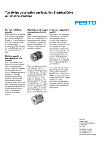
system of any type, always When considering mounting stepper motor system and
work from the end effector servo and stepper motors on you want to use micro
(gripper or vacuum) upwards. to mechanical axis, ensure stepping, your step pulse
Firstly size the gripper, then you allow for misalignment. from your PLC or stepper
any rotary actuator Flexible couplings such as card must be able to keep up
requirements. After this, size “Oldham” type or bellows, with your performance
the vertical (Z axis) and then couplings are ideal. expectations. i.e. a typical
any horizontals (X and Y stepper motor may have 200
axis). steps per revolution. If you
want smoother and more
Minimise quantity of precise motion you can of
bearings in multi axis course on most systems go
solutions to 32nd step micro stepping.
If your requirement is for a This now gives 6,400 steps
multi axis solution, the best per revolution.
practice is to reduce the These usually come supplied
amount of bearings between with set screw fixing or If you want to rotate at 900
the rigid frame and the clamping. They also act as a rpm, it requires 5,760,000
product. By keeping this to a mechanical fuse. If the drive pulses per minute which is
minimum (5 bearings crashes, the coupling slips 96,000 pulses per second or
absolute maximum) you and therefore minimised 96khz. You must ensure this
minimise the cumulative expensive damage to the can be achieved. This is often
deflection and therefore ballscrew or belt drive. The overlooked by the
improve accuracy. Also, if the ideal solution is to select a mechanical designer when
axes are electrical, problems manufacture that can supply sizing the system as they do
are compounded as high play the axis, coupling housing, not deal directly with the PLC
and deflection effects the coupling, flange and motor. specification.
tuning of the axis and This minimised the risk and
produces an unstable gives a guaranteed solution.
system.
Festo Ltd
Caswell Road
Brackmills Trading Estate
Northampton
NN4 7PY
Tel: (0800) 626422
Fax: (01604) 667001
Info_gb@festo.com
www.festo.com/gb/edrives
2. Benefits of stepper & What is inertia mismatch Avoiding unnecessary
servo motors ratio? strain & wear on drive
Stepper motor technology is Most stepper and servo belts & bearings
often thought of as the poor systems are sized not on the When linking two axes
cousin in motion control torque requirement but on together in a parallel
terms when compared with the inertia requirement configuration, ensure the
servo. This is often a (although torque is an coupling shaft between the
misconception as, although important factor). If a motor axes is mounted on the same
the dynamics are lower than is attached to a load that has shaft as the motor. This
servo, a correctly sized a much higher inertia than ensures rigid power
stepper system can offer the rotor (rotating part of the transmission and guarantees
major cost benefits over a motor), the load will tend to the two axes run together in
servo. Remember to oversize drive the motor and not the a synchronous manner.
a stepper by at least 30%, to other way round (a little like Mounting the coupling shaft
ensure it never loses steps a smart car pulling a 2 tonne on the opposite end of the
and you will have a very caravan). This is not a good axis to motor introduces a lag
reliable and cost effective situation to be in and and additional strain on the
system. If in doubt, always therefore it is important to belt and bearings.
seek advice from a ensure the load inertia is not
manufacturer that offers both too high in relation to the
technologies and you will be rotor inertia.
assured of a non-biased
optimum solution. In most simple positioning
tasks, this inertia can be up
to 10: 1 (load:rotor). A CNC
machine that requires very
precise positioning
throughout its movement
would have an inertia match
of perhaps 1:1.
If the load inertia is too high,
a gearbox can be fitted which
Servo motor will help considerably in
reducing this ratio (a 4:1
gearbox will reduce the
inertia of the load by nearly
16 times).
Stepper motor
Festo Ltd
Caswell Road
Brackmills Trading Estate
Northampton
NN4 7PY
Tel: (0800) 626422
Fax: (01604) 667001
Info_gb@festo.com
www.festo.com/gb/edrives
3. The importance of This means that many axis The importance of
identifying the allowance appear longer than others for effective cable
for reserve stroke the same stroke length. It is management systems
Remember to check whether possible to use some of this Do not discount the
over travel or stroke reserve stroke reserve and therefore importance of cable
is included on your reduce the length of the axis, management systems when
mechanical axis. Many depending on the speed and integrating electric drives
manufacturers include a load of the application. into an application.
distance at each end of the Beware, if this reserve is
axis which is not part of the totally used up, it can lead to These issues are often as
stroke of the system, but not a dangerous catastrophic important as the
all manufacturers do this. failure of the system. of the drive itself. Badly
This feature ensures that if a designed and installed cable
position is programmed in to management can effect the
the controller incorrectly and tuning of a drive, create a
the motor hits the end limit very noisy application, lead
sensor at speed, the motor to premature failure of the
can decelerate down before tubes and cables and
hits the physical end of the dangerous for operators.
axis.
Energy chain systems should
be treated as an integral part
of the design and not as an
add-on once the system has
been designed.
Ensure your electric drive
supplier has a grasp of these
issues and ensure their axis
mountings are designed for
the cable management and
energy chain systems.
Festo Ltd
Caswell Road
Brackmills Trading Estate
Northampton
NN4 7PY
Tel: (0800) 626422
Fax: (01604) 667001
Info_gb@festo.com
www.festo.com/gb/edrives
4. What are the differences Ballscrews, which
between spindle drives, confusingly are often referred
lead screws and to as spindle drives, consist
of a ground or rolled spindle
ballscrews?
and a helical nut which
Many people ask what the
contains recirculating ball
main differences are between
bearings. Ballscrews give a
spindle drives, lead screws
long life and play free,
and ballscrews. Much of the
accurate positioning.
confusion stems from
Disadvantage are the higher
terminology and market
cost and they are not self
location. Terminology in the
locking, needing a braked
USA often varies from that in
motor in vertical
Western Europe.
Lead screws, often called
trapezoidal spindles, consist
of a trapezoidal thread form
and often a polymer nut.
They tend to be low cost and
offer the benefit of being self
locking due to the thread
form. Disadvantages are
lower life expectancy and a
small amount of play.
Ballscrew
Nigel Dawson is
Product Manager for
electric drive
automation at Festo
Festo Ltd
Caswell Road
Brackmills Trading Estate
Northampton
NN4 7PY
Tel: (0800) 626422
Fax: (01604) 667001
Info_gb@festo.com
www.festo.com/gb/edrives