Sachpazis: Raft Foundation Analysis & Design BS8110:part 1-1997_plain slab with edge wall load example
•
4 gefällt mir•6,640 views

Raft Foundation Analysis & Design BS8110:part 1-1997_plain slab with edge wall load example

Empfohlen
Weitere ähnliche Inhalte
Was ist angesagt?
Was ist angesagt? (20)
Andere mochten auch
Andere mochten auch (20)
Ähnlich wie Sachpazis: Raft Foundation Analysis & Design BS8110:part 1-1997_plain slab with edge wall load example
Ähnlich wie Sachpazis: Raft Foundation Analysis & Design BS8110:part 1-1997_plain slab with edge wall load example (20)
Mehr von Dr.Costas Sachpazis
Mehr von Dr.Costas Sachpazis (20)
Kürzlich hochgeladen
Kürzlich hochgeladen (20)
Sachpazis: Raft Foundation Analysis & Design BS8110:part 1-1997_plain slab with edge wall load example
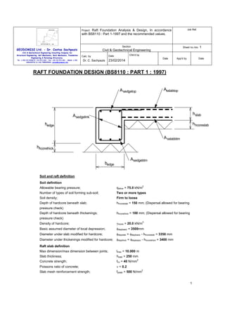
- 1. Raft Foundation Analysis & Design, In accordance with BS8110 : Part 1-1997 and the recommended values. Job Ref. Section Sheet no./rev. 1 Project: GEODOMISI Ltd. - Dr. Costas Sachpazis Civil & Geotechnical Engineering Consulting Company for Structural Engineering, Soil Mechanics, Rock Mechanics, Foundation Engineering & Retaining Structures. Tel.: (+30) 210 5238127, 210 5711263 - Fax.:+30 210 5711461 - Mobile: (+30) 6936425722 & (+44) 7585939944, costas@sachpazis.info Civil & Geotechnical Engineering Chk'd by Date Calc. by Dr. C. Sachpazis Date 23/02/2014 App'd by Date RAFT FOUNDATION DESIGN (BS8110 : PART 1 : 1997) Asslabtop A sedgetop hslab A sedgelink hhcoreslab hedge A sslabbtm hhcorethick Asedgebtm bedge Soil and raft definition Soil definition Allowable bearing pressure; 2 qallow = 75.0 kN/m Number of types of soil forming sub-soil; Two or more types Soil density; Firm to loose Depth of hardcore beneath slab; hhcoreslab = 150 mm; (Dispersal allowed for bearing pressure check) Depth of hardcore beneath thickenings; hhcorethick = 100 mm; (Dispersal allowed for bearing pressure check) 3 Density of hardcore; γhcore = 20.0 kN/m Basic assumed diameter of local depression; φdepbasic = 3500mm Diameter under slab modified for hardcore; φdepslab = φdepbasic - hhcoreslab = 3350 mm Diameter under thickenings modified for hardcore; φdepthick = φdepbasic - hhcorethick = 3400 mm Raft slab definition Max dimension/max dimension between joints; lmax = 10.000 m Slab thickness; hslab = 250 mm Concrete strength; fcu = 40 N/mm 2 Poissons ratio of concrete; ν = 0.2 Slab mesh reinforcement strength; fyslab = 500 N/mm 2 1
- 2. Raft Foundation Analysis & Design, In accordance with BS8110 : Part 1-1997 and the recommended values. Job Ref. Section Sheet no./rev. 1 Project: GEODOMISI Ltd. - Dr. Costas Sachpazis Civil & Geotechnical Engineering Consulting Company for Structural Engineering, Soil Mechanics, Rock Mechanics, Foundation Engineering & Retaining Structures. Tel.: (+30) 210 5238127, 210 5711263 - Fax.:+30 210 5711461 - Mobile: (+30) 6936425722 & (+44) 7585939944, costas@sachpazis.info Civil & Geotechnical Engineering Calc. by Dr. C. Sachpazis Chk'd by Date Date 23/02/2014 Partial safety factor for steel reinforcement; App'd by Date γs = 1.15 From C&CA document ‘Concrete ground floors’ Table 5 Minimum mesh required in top for shrinkage; A142; Actual mesh provided in top; A393 (Asslabtop = 393 mm2/m) Mesh provided in bottom; A393 (Asslabbtm = 393 mm /m) Top mesh bar diameter; φslabtop = 10 mm 2 Bottom mesh bar diameter; φslabbtm = 10 mm Cover to top reinforcement; ctop = 20 mm Cover to bottom reinforcement; cbtm = 40 mm Average effective depth of top reinforcement; dtslabav = hslab - ctop - φslabtop = 220 mm Average effective depth of bottom reinforcement; dbslabav = hslab - cbtm - φslabbtm = 200 mm Overall average effective depth; dslabav = (dtslabav + dbslabav)/2 = 210 mm Minimum effective depth of top reinforcement; dtslabmin = dtslabav - φslabtop/2 = 215 mm Minimum effective depth of bottom reinforcement; dbslabmin = dbslabav - φslabbtm/2 = 195 mm Edge beam definition Overall depth; hedge = 500 mm Width; bedge = 500 mm Strength of main bar reinforcement; fy = 500 N/mm Strength of link reinforcement; fys = 500 N/mm Reinforcement provided in top; 4 T16 bars (Asedgetop = 804 mm ) Reinforcement provided in bottom; 3 T16 bars (Asedgebtm = 603 mm ) 2 2 2 2 Link reinforcement provided; 2 T10 legs at 300 ctrs (Asv/sv = 0.524 mm) Bottom cover to links; cbeam = 40 mm Effective depth of top reinforcement; dedgetop = hedge - ctop - φslabtop - φedgelink - φedgetop/2 = 452 mm Effective depth of bottom reinforcement; dedgebtm = hedge - cbeam - φedgelink - φedgebtm/2 = 442 mm Internal slab design checks Basic loading 3 2 Slab self weight; wslab = 24 kN/m × hslab = 6.0 kN/m Hardcore; whcoreslab = γhcore × hhcoreslab = 3.0 kN/m 2 Applied loading Uniformly distributed dead load; Uniformly distributed live load; 2 wDudl = 2.0 kN/m 2 wLudl = 5.0 kN/m Internal slab bearing pressure check Total uniform load at formation level; wudl = wslab + whcoreslab + wDudl + wLudl = 16.0 kN/m 2 PASS - wudl <= qallow - Applied bearing pressure is less than allowable 2
- 3. Raft Foundation Analysis & Design, In accordance with BS8110 : Part 1-1997 and the recommended values. Job Ref. Section Sheet no./rev. 1 Project: GEODOMISI Ltd. - Dr. Costas Sachpazis Civil & Geotechnical Engineering Consulting Company for Structural Engineering, Soil Mechanics, Rock Mechanics, Foundation Engineering & Retaining Structures. Civil & Geotechnical Engineering Calc. by Tel.: (+30) 210 5238127, 210 5711263 - Fax.:+30 210 5711461 - Mobile: (+30) 6936425722 & (+44) 7585939944, costas@sachpazis.info Dr. C. Sachpazis Chk'd by Date Date 23/02/2014 App'd by Date Internal slab bending and shear check Applied bending moments Span of slab; lslab = φdepslab + dtslabav = 3570 mm Ultimate self weight udl; wswult = 1.4 × wslab = 8.4 kN/m Self weight moment at centre; Mcsw = wswult × lslab × (1 + ν) / 64 = 2.0 kNm/m Self weight moment at edge; Mesw = wswult × lslab / 32 = 3.3 kNm/m Self weight shear force at edge; Vsw = wswult × lslab / 4 = 7.5 kN/m 2 2 2 Moments due to applied uniformly distributed loads Ultimate applied udl; 2 wudlult = 1.4 × wDudl + 1.6 × wLudl = 10.8 kN/m 2 Moment at centre; Mcudl = wudlult × lslab × (1 + ν) / 64 = 2.6 kNm/m Moment at edge; Meudl = wudlult × lslab / 32 = 4.3 kNm/m Shear force at edge; Vudl = wudlult × lslab / 4 = 9.6 kN/m 2 Resultant moments and shears Total moment at edge; MΣe = 7.6 kNm/m Total moment at centre; MΣc = 4.6 kNm/m Total shear force; VΣ = 17.1 kN/m Reinforcement required in top 2 K factor; Kslabtop = MΣe/(fcu × dtslabav ) = 0.004 Lever arm; zslabtop = dtslabav × min(0.95, 0.5 + √(0.25 - Kslabtop/0.9)) = 209.0 mm Area of steel required for bending; Asslabtopbend = MΣe/((1.0/γs) × fyslab × zslabtop) = 84 2 mm /m 2 Minimum area of steel required; Asslabmin = 0.0013 × hslab = 325 mm /m Area of steel required; Asslabtopreq = max(Asslabtopbend, Asslabmin) = 325 mm /m 2 PASS - Asslabtopreq <= Asslabtop - Area of reinforcement provided in top to span local depressions is adequate Reinforcement required in bottom 2 K factor; Kslabbtm = MΣc/(fcu × dbslabav ) = 0.003 Lever arm; zslabbtm = dbslabav × min(0.95, 0.5 + √(0.25 - Kslabbtm/0.9)) = 190.0 mm Area of steel required for bending; Asslabbtmbend = MΣc/((1.0/γs) × fyslab × zslabbtm) = 56 2 mm /m Area of steel required; Asslabbtmreq = max(Asslabbtmbend, Asslabmin) = 325 2 mm /m PASS - Asslabbtmreq <= Asslabbtm - Area of reinforcement provided in bottom to span local depressions is adequate Shear check 2 Applied shear stress; v = VΣ/dtslabmin = 0.080 N/mm Tension steel ratio; ρ = 100 × Asslabtop/dtslabmin = 0.183 3
- 4. Raft Foundation Analysis & Design, In accordance with BS8110 : Part 1-1997 and the recommended values. Job Ref. Section Sheet no./rev. 1 Project: GEODOMISI Ltd. - Dr. Costas Sachpazis Civil & Geotechnical Engineering Civil & Geotechnical Engineering Consulting Company for Structural Engineering, Soil Mechanics, Rock Mechanics, Foundation Engineering & Retaining Structures. Calc. by Dr. C. Sachpazis Tel.: (+30) 210 5238127, 210 5711263 - Fax.:+30 210 5711461 - Mobile: (+30) 6936425722 & (+44) 7585939944, costas@sachpazis.info Chk'd by Date Date 23/02/2014 App'd by Date From BS8110-1:1997 - Table 3.8; Design concrete shear strength; vc = 0.490 N/mm 2 PASS - v <= vc - Shear capacity of the slab is adequate Internal slab deflection check Basic allowable span to depth ratio; Ratiobasic = 26.0 Moment factor; Mfactor = MΣc/dbslabav = 0.115 N/mm Steel service stress; fs = 2/3 × fyslab × Asslabbtmbend/Asslabbtm = 47.109 N/mm 2 2 2 2 MFslab = min(2.0, 0.55 + [(477N/mm - fs)/(120 × Modification factor; 2 (0.9N/mm + Mfactor))]) MFslab = 2.000 Modified allowable span to depth ratio; Ratioallow = Ratiobasic × MFslab = 52.000 Actual span to depth ratio; Ratioactual = lslab/ dbslabav = 17.850 PASS - Ratioactual <= Ratioallow - Slab span to depth ratio is adequate Edge beam design checks Basic loading 2 whcorethick = γhcore × hhcorethick = 2.0 kN/m Hardcore; 3 wedge = 24 kN/m × hedge × bedge = 6.0 kN/m Edge beam self weight; Edge beam bearing pressure check Effective bearing width of edge beam; bbearing = bedge = 500 mm Total uniform load at formation level; wudledge = wDudl+wLudl+wedge/bbearing+whcorethick = 21.0 2 kN/m PASS - wudledge <= qallow - Applied bearing pressure is less than allowable Edge beam bending check Divider for moments due to udl’s; βudl = 10.0 Applied bending moments Span of edge beam; ledge = φdepthick + dedgetop = 3852 mm Ultimate self weight udl; wedgeult = 1.4 × wedge = 8.4 kN/m Ultimate slab udl (approx); wedgeslab = max(0 kN/m, 1.4×wslab×((φdepthick/2 × 3/4)- bedge)) = 6.5 kN/m 2 Self weight and slab bending moment; Medgesw = (wedgeult + wedgeslab) × ledge /βudl = 22.1 kNm Self weight shear force; Vedgesw = (wedgeult + wedgeslab) × ledge/2 = 28.7 kN Moments due to applied uniformly distributed loads Ultimate udl (approx); wedgeudl = wudlult × φdepthick/2 × 3/4 = 13.8 kN/m Bending moment; Medgeudl = wedgeudl × ledge /βudl = 20.4 kNm Shear force; Vedgeudl = wedgeudl × ledge/2 = 26.5 kN 2 Resultant moments and shears Total moment (hogging and sagging); MΣedge = 42.6 kNm 4
- 5. Raft Foundation Analysis & Design, In accordance with BS8110 : Part 1-1997 and the recommended values. Job Ref. Section Sheet no./rev. 1 Project: GEODOMISI Ltd. - Dr. Costas Sachpazis Civil & Geotechnical Engineering Consulting Company for Structural Engineering, Soil Mechanics, Rock Mechanics, Foundation Engineering & Retaining Structures. Tel.: (+30) 210 5238127, 210 5711263 - Fax.:+30 210 5711461 - Mobile: (+30) 6936425722 & (+44) 7585939944, costas@sachpazis.info Civil & Geotechnical Engineering Dr. C. Sachpazis Maximum shear force; Chk'd by Date Calc. by Date 23/02/2014 App'd by Date VΣedge = 55.2 kN Reinforcement required in top Width of section in compression zone; bedgetop = bedge = 500 mm Average web width; bw = bedge = 500 mm K factor; Kedgetop = MΣedge/(fcu × bedgetop × dedgetop ) = 0.010 Lever arm; zedgetop = dedgetop × min(0.95, 0.5 + √(0.25 - 2 Kedgetop/0.9)) = 429 mm Area of steel required for bending; mm Asedgetopbend = MΣedge/((1.0/γs) × fy × zedgetop) = 228 2 2 Minimum area of steel required; Asedgetopmin = 0.0013 × 1.0 × bw × hedge = 325 mm Area of steel required; Asedgetopreq = max(Asedgetopbend, Asedgetopmin) = 325 mm 2 PASS - Asedgetopreq <= Asedgetop - Area of reinforcement provided in top of edge beams is adequate Reinforcement required in bottom Width of section in compression zone; bedgebtm = bedge + 0.1 × ledge = 885 mm K factor; Kedgebtm = MΣedge/(fcu × bedgebtm × dedgebtm ) = 0.006 Lever arm; zedgebtm = dedgebtm × min(0.95, 0.5 + √(0.25 - 2 Kedgebtm/0.9)) = 420 mm Area of steel required for bending; mm Asedgebtmbend = MΣedge/((1.0/γs) × fy × zedgebtm) = 233 2 2 Minimum area of steel required; Asedgebtmmin = 0.0013 × 1.0 × bw × hedge = 325 mm Area of steel required; Asedgebtmreq = max(Asedgebtmbend, Asedgebtmmin) = 325 mm 2 PASS - Asedgebtmreq <= Asedgebtm - Area of reinforcement provided in bottom of edge beams is adequate Edge beam shear check 2 Applied shear stress; vedge = VΣedge/(bw × dedgetop) = 0.244 N/mm Tension steel ratio; ρedge = 100 × Asedgetop/(bw × dedgetop) = 0.356 From BS8110-1:1997 - Table 3.8 Design concrete shear strength; vcedge = 0.524 N/mm 2 2 vedge <= vcedge + 0.4N/mm - Therefore minimum links required Link area to spacing ratio required; 2 Asv_upon_svreqedge = 0.4N/mm × bw/((1.0/γs) × fys) = 0.460 mm Link area to spacing ratio provided; 2 Asv_upon_svprovedge = Nedgelink×π×φedgelink /(4×svedge) = 0.524 mm PASS - Asv_upon_svreqedge <= Asv_upon_svprovedge - Shear reinforcement provided in edge beams is adequate 5
- 6. Raft Foundation Analysis & Design, In accordance with BS8110 : Part 1-1997 and the recommended values. Job Ref. Section Sheet no./rev. 1 Project: GEODOMISI Ltd. - Dr. Costas Sachpazis Civil & Geotechnical Engineering Consulting Company for Structural Engineering, Soil Mechanics, Rock Mechanics, Foundation Engineering & Retaining Structures. Tel.: (+30) 210 5238127, 210 5711263 - Fax.:+30 210 5711461 - Mobile: (+30) 6936425722 & (+44) 7585939944, costas@sachpazis.info Civil & Geotechnical Engineering Calc. by Dr. C. Sachpazis Chk'd by Date 23/02/2014 Date App'd by Date Corner design checks Basic loading Corner load number 1 Load type; Line load in x direction Dead load; wDcorner1 = 9.6 kN/m Live load; wLcorner1 = 0.0 kN/m Ultimate load; wultcorner1 = 1.4 × wDcorner1 + 1.6 × wLcorner1 = 13.4 kN/m Centroid of load from outside face of raft; ycorner1 = 100 mm Corner load number 2 Load type; Line load in y direction Dead load; wDcorner2 = 9.6 kN/m Live load; wLcorner2 = 0.0 kN/m Ultimate load; wultcorner2 = 1.4 × wDcorner2 + 1.6 × wLcorner2 = 13.4 kN/m Centroid of load from outside face of raft; xcorner2 = 100 mm Corner bearing pressure check Total uniform load at formation level; wudlcorner = wDudl+wLudl+wedge/bbearing+whcorethick = 21.0 2 kN/m Net bearing press avail to resist line/point loads; 2 qnetcorner = qallow - wudlcorner = 54.0 kN/m Total line/point loads Total unfactored line load in x direction; wΣlinex = 9.6 kN/m Total ultimate line load in x direction; wΣultlinex =13.4 kN/m Total unfactored line load in y direction; wΣliney = 9.6 kN/m Total ultimate line load in y direction; wΣultliney = 13.4 kN/m Total unfactored point load; wΣpoint = 0.0 kN Total ultimate point load; wΣultpoint = 0.0 kN Length of side of sq reqd to resist line/point loads; pcorner 2 =[wΣlinex+wΣliney+√((wΣlinex+wΣliney) +4×qnetcorner×wΣpoint)]/(2×qnetcorner) pcorner = 356 mm Bending moment about x-axis due to load/reaction eccentricity Moment due to load 1 (x line); Mx1 = max(0 kNm, wultcorner1 × pcorner × (pcorner/2 - ycorner1)) = 0.4 kNm Total moment about x axis; MΣx = 0.4 kNm Bending moment about y-axis due to load/reaction eccentricity Moment due to load 2 (y line); My2 = max(0 kNm, wultcorner2 × pcorner × (pcorner/2 - xcorner2)) = 0.4 kNm Total moment about y axis; MΣy = 0.4 kNm Check top reinforcement in edge beams for load/reaction eccentric moment 6
- 7. Raft Foundation Analysis & Design, In accordance with BS8110 : Part 1-1997 and the recommended values. Job Ref. Section Sheet no./rev. 1 Project: GEODOMISI Ltd. - Dr. Costas Sachpazis Civil & Geotechnical Engineering Consulting Company for Structural Engineering, Soil Mechanics, Rock Mechanics, Foundation Engineering & Retaining Structures. Civil & Geotechnical Engineering Calc. by Tel.: (+30) 210 5238127, 210 5711263 - Fax.:+30 210 5711461 - Mobile: (+30) 6936425722 & (+44) 7585939944, costas@sachpazis.info Dr. C. Sachpazis Chk'd by Date Date 23/02/2014 Max moment due to load/reaction eccentricity; App'd by Date MΣ = max(MΣx, MΣy) = 0.4 kNm Assume all of this moment is resisted by edge beam From edge beam design checks away from corners Moment due to edge beam spanning depression; MΣedge = 42.6 kNm Total moment to be resisted; MΣcornerbp = MΣ + MΣedge = 42.9 kNm Width of section in compression zone; bedgetop = bedge = 500 mm K factor; Kcornerbp = MΣcornerbp/(fcu × bedgetop × dedgetop ) = 0.011 Lever arm; zcornerbp = dedgetop × min(0.95, 0.5 + √(0.25 - 2 Kcornerbp/0.9)) = 429 mm Ascornerbp = MΣcornerbp /((1.0/γs) × fy × zcornerbp) = 230 Total area of top steel required; mm 2 PASS - Ascornerbp <= Asedgetop - Area of reinforcement provided to resist eccentric moment is adequate The allowable bearing pressure at the corner will not be exceeded Corner beam bending check Cantilever span of edge beam; lcorner = φdepthick/√(2) + dedgetop/2 = 2630 mm Moment and shear due to self weight Ultimate self weight udl; wedgeult = 1.4 × wedge = 8.4 kN/m Average ultimate slab udl (approx); wcornerslab = max(0 kN/m,1.4×wslab×(φdepthick/(√(2)×2)- bedge)) = 5.9 kN/m Self weight and slab bending moment; 2 Mcornersw = (wedgeult + wcornerslab) × lcorner /2 = 49.5 kNm Self weight and slab shear force; Vcornersw = (wedgeult + wcornerslab) × lcorner = 37.6 kN Moment and shear due to udls Maximum ultimate udl; wcornerudl = ((1.4×wDudl)+(1.6×wLudl)) × φdepthick/√(2) = 26.0 kN/m 2 Bending moment; Mcornerudl = wcornerudl × lcorner /6 = 29.9 kNm Shear force; Vcornerudl = wcornerudl × lcorner/2 = 34.1 kN Moment and shear due to line loads in x direction 2 Bending moment; Mcornerlinex = wΣultlinex × lcorner /2 = 46.5 kNm Shear force; Vcornerlinex = wΣultlinex × lcorner = 35.3 kN Moment and shear due to line loads in y direction 2 Bending moment; Mcornerliney = wΣultliney × lcorner /2 = 46.5 kNm Shear force; Vcornerliney = wΣultliney × lcorner = 35.3 kN Total moments and shears due to point loads Bending moment about x axis; Mcornerpointx = 0.0 kNm Bending moment about y axis; Mcornerpointy = 0.0 kNm Shear force; Vcornerpoint = 0.0 kN Resultant moments and shears 7
- 8. Raft Foundation Analysis & Design, In accordance with BS8110 : Part 1-1997 and the recommended values. Job Ref. Section Sheet no./rev. 1 Project: GEODOMISI Ltd. - Dr. Costas Sachpazis Civil & Geotechnical Engineering Consulting Company for Structural Engineering, Soil Mechanics, Rock Mechanics, Foundation Engineering & Retaining Structures. Tel.: (+30) 210 5238127, 210 5711263 - Fax.:+30 210 5711461 - Mobile: (+30) 6936425722 & (+44) 7585939944, costas@sachpazis.info Civil & Geotechnical Engineering Chk'd by Date Calc. by Dr. C. Sachpazis Date 23/02/2014 Total moment about x axis; App'd by Date MΣcornerx = Mcornersw+ Mcornerudl+ Mcornerliney+ Mcornerpointx = 125.9 kNm Total shear force about x axis; VΣcornerx = Vcornersw+ Vcornerudl+ Vcornerliney + Vcornerpoint = 107.1 kN Total moment about y axis; MΣcornery = Mcornersw+ Mcornerudl+ Mcornerlinex+ Mcornerpointy = 125.9 kNm Total shear force about y axis; VΣcornery = Vcornersw+ Vcornerudl+ Vcornerlinex + Vcornerpoint = 107.1 kN Deflection of both edge beams at corner will be the same therefore design for average of these moments and shears Design bending moment; MΣcorner = (MΣcornerx + MΣcornery)/2 = 125.9 kNm Design shear force; VΣcorner = (VΣcornerx + VΣcornery)/2 = 107.1 kN Reinforcement required in top of edge beam 2 K factor; Kcorner = MΣcorner/(fcu × bedgetop × dedgetop ) = 0.031 Lever arm; zcorner = dedgetop × min(0.95, 0.5 + √(0.25 - Kcorner/0.9)) = 429 mm Area of steel required for bending; Ascornerbend = MΣcorner/((1.0/γs) × fy × zcorner) = 674 2 mm Minimum area of steel required; Ascornermin = Asedgetopmin = 325 mm Area of steel required; Ascorner = max(Ascornerbend, Ascornermin) = 674 mm 2 2 PASS - Ascorner <= Asedgetop - Area of reinforcement provided in top of edge beams at corners is adequate Corner beam shear check Average web width; bw = bedge = 500 mm Applied shear stress; vcorner = VΣcorner/(bw × dedgetop) = 0.474 N/mm Tension steel ratio; ρcorner = 100 × Asedgetop/(bw × dedgetop) = 0.356 From BS8110-1:1997 - Table 3.8 Design concrete shear strength; vccorner = 0.508 N/mm 2 2 2 vcorner <= vccorner + 0.4N/mm - Therefore minimum links required Link area to spacing ratio required; 2 Asv_upon_svreqcorner = 0.4N/mm × bw/((1.0/γs) × fys) = 0.460 mm Link area to spacing ratio provided; 2 Asv_upon_svprovedge = Nedgelink×π×φedgelink /(4×svedge) = 0.524 mm PASS - Asv_upon_svreqcorner <= Asv_upon_svprovedge - Shear reinforcement provided in edge beams at corners is adequate Corner beam deflection check Basic allowable span to depth ratio; Ratiobasiccorner = 7.0 Moment factor; Mfactorcorner = MΣcorner/(bedgetop × dedgetop ) = 1.232 N/mm 2 2 8
- 9. Raft Foundation Analysis & Design, In accordance with BS8110 : Part 1-1997 and the recommended values. Job Ref. Section Sheet no./rev. 1 Project: GEODOMISI Ltd. - Dr. Costas Sachpazis Civil & Geotechnical Engineering Consulting Company for Structural Engineering, Soil Mechanics, Rock Mechanics, Foundation Engineering & Retaining Structures. Tel.: (+30) 210 5238127, 210 5711263 - Fax.:+30 210 5711461 - Mobile: (+30) 6936425722 & (+44) 7585939944, costas@sachpazis.info Civil & Geotechnical Engineering Calc. by Dr. C. Sachpazis 23/02/2014 Date App'd by Date fscorner = 2/3 × fy × Ascornerbend/Asedgetop = 279.448 Steel service stress; N/mm Chk'd by Date 2 2 MFcorner=min(2.0,0.55+[(477N/mm - Modification factor; 2 fscorner)/(120×(0.9N/mm +Mfactorcorner))]) MFcorner = 1.322 Modified allowable span to depth ratio; Ratioallowcorner = Ratiobasiccorner × MFcorner = 9.255 Actual span to depth ratio; Ratioactualcorner = lcorner/ dedgetop = 5.819 PASS - Ratioactualcorner <= Ratioallowcorner - Edge beam span to depth ratio is adequate 9