NCG CAM
•
0 gefällt mir•617 views

NCG CAM is a easy to use standalone CAM system for the shop floor. The toolroom machinists perfect partner. Reliable iges reader makes it a perfect match for any CAD or design system. Multi threaded for performance, saving time and money

Empfohlen
Weitere ähnliche Inhalte
Was ist angesagt?
Was ist angesagt? (19)
Andere mochten auch
Andere mochten auch (18)
Ähnlich wie NCG CAM
Ähnlich wie NCG CAM (20)
Kürzlich hochgeladen
Kürzlich hochgeladen (20)
NCG CAM
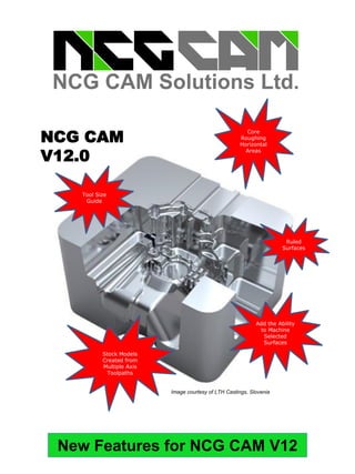
- 1. New Features for NCG CAM V12 NCG CAM V11 Add the Ability to Machine Selected Surfaces Core Roughing Horizontal Areas Stock Models Created from Multiple Axis Toolpaths NCG CAM V12.0 Image courtesy of LTH Castings, Slovenia Tool Size Guide Ruled Surfaces
- 2. 2 NCG CAM New Features V12– Base Module Different XY to Z Thickness for Ball-nosed Cutters This new feature can be used in instances where the user wants to use a ball-nosed cutter and have a negative thickness in X & Y, but not in Z, or where the negative thickness is greater than the corner radius. Use Double Precision Storage in Database Files This will not be visually obvious to the user like most features, as it is how surfaces, boundaries and toolpaths are stored in the database. Storing data in double precision will allow for greater accuracy on larger jobs (typically those larger than 1000mm) and if working a long way from the part origin, but also on smaller part close to the origin where extremely tight tolerances (<0.001mm) are required. Added the Ability to Machine Selected Surfaces This new functionality will allow the user to select the individual surfaces to machine and then set the machine selected surfaces option, to machine to the surfaces very edge, without the need to create a boundary first.
- 3. 3 This new enhancement allows the user to define a clearance for the shank of the cutter in a similar way to the tool holder clearance. This will make it possible to machine without having the shank rubbing on existing machining. Shaft Profile Analysis Defining the correct tool shape and holder will ensure the toolpaths are gouge free, but it can result in material being left on the part. The shaft profile allows a different approach – what cutter and holder will 'fit' best. The user is able to try different cutter shanks and holder combinations after creating the toolpath. The shaft profile provides a graphical view, of the required body and cylindrical lengths of the cutter. The shaft profile now checks a tapered shank section of the tool in addition to the holder, and shows the area where the tool could gouge. Ruled Surfaces This new feature will allow the user to generate a ruled surface between curves. This is in addition to the existing planar patch feature. In combination with the new extract curves functionality in v11, the user can for example create surfaces to extend the edge of surfaces to machine past the real surfaces edge. Cutter Shank Clearance
- 4. 4 This new feature allows the user to create a thread milling cycle. The canned cycles menu and dialog has been changed slightly. Thread MillingThread MillingThread Milling Central Folder for Tape Files This new feature allows the user to define a global folder for tape files when post-processing. This will save some users from having to pick the folder on each job. This will benefit users who always post their NC tape files to the same folder, or machine folder.
- 5. 5 Setting the Datum Based on the Min, Center or Max of the Surfaces This enhancement provides the user with more control over the horizontal lead-in and lead-out arcs. This should be beneficial for waterline passes, where a large step-down is used, as the toolpath will not helix down the side of the job. Simplified Lead Moves & Elongated Leads for Waterline Passes This enhancement allows the user to pick min, center or max position from graphical image rather than typing mx() cy() Mz() making it more user friendly. Picking the required position in the image will automatically update the XYZ coordinates with the correct values to position that part of the model at X0 Y0 Z0.
- 6. 6 This new feature allows the user to define a circle or a disk the size of the cutter, that will move with the cursor when looking down the tool axis. This should allow the user to determine where a particular cutter diameter can get, without having to create the passes or do a lot of measuring. It can also help when creating boundaries with mouse hits for a particular cutter size. Tool Size Guide User Defined Text Editor This enhancement allows the user to define their preferred text editor, which will be used when viewing a tape file. Previously the user could only use Notepad. Cutter Shank ClearanceCore Horizontal Area Passes This new feature will allow users to machine horizontal areas plunging off the job and then milling in from the side. In certain materials, such as Inconel (a nickel-chromium-based superalloy) and many other steels after heat treatment, machining in from the side will give far better tool life.
- 7. 7 Stock Models Created from Multiple Axis Toolpaths Users are now able to make a single stock model from toolpaths with multiple tool axis, (not just single tool axis), which will enable the user to visualise what the user has or has not machined with a combination of 3+2 and / or 5-axis toolpaths. The same stock model could also be used for rest roughing after a number of machining operations with different tool axes or to edit other toolpaths too. Stock Models Created from Multiple Axis ToolpathsStock Models Created from Multiple Axis Toolpaths VERICUT Tool List Creator A new feature has been added in the NCG CAM post-processors, for users that use VERICUTTM to double check their NC Tape Files for potential problems where a tilted axis could cause a collision between machine parts. It is now possible to set an option in the post processor options that will create a tool list (*.tls) for the post processed operations. Once VERICUTTM is started that file can be loaded, defining the cutter and tool holder based on what was defined for the toolpath in NCG CAM.
- 8. Head Office: NCG CAM Solutions Ltd Silverwood Lodge, Ely Road Waterbeach, Cambridge, CB25 9NN ENGLAND, UK Tel: +44 (0)1223 863911 +44 (0)1353 699840 Email: estelle@ncgcam.com Web: www.ncgcam.com Authorised Reseller Contact Details: Ideas Design Solution (P) Ltd # 8/37 (1st Floor), Above DCB Bank Jharsa Road, Kirti Nagar, Gurgaon-122001 Contact Person :- Vijender Pratap Singh Email :- vijender@idspl.com Phone: 9015730393, 0124-4721999