SlideShare ist ein Scribd-Unternehmen logo
1 von 57
Downloaden Sie, um offline zu lesen
Information in this catalog is subject to change without notice.
5-7, Nihonbashi Odemma-cho, Chuo-ku, Tokyo, 103-0011, Japan
URL http://www.fujielectric.co.jp/fcs/eng
INDIVIDUALCATALOGfromD&CCATALOG20thEdition
11
LOW VOLTAGE PRODUCTS Up to 600 Volts
Individual
catalog No.
01 Magnetic Contactors and Starters
Thermal Overload Relays, Solid-state Contactors
02
Industrial Relays, Industrial Control Relays
Annunciator Relay Unit, Time Delay Relays
Manual Motor Starters and Contactors
Combination Starters
Pushbuttons, Selector Switches, Pilot Lights
Rotary Switches, Cam Type Selector Switches
Panel Switches, Terminal Blocks, Testing Terminals
Molded Case Circuit Breakers
Air Circuit Breakers
Earth Leakage Circuit Breakers
Earth Leakage Protective Relays
Measuring Instruments, Arresters, Transducers
Power Factor Controllers
Power Monitoring Equipment (F-MPC)
Circuit Protectors
Low Voltage Current-Limiting Fuses
03
04
05
06
07
08
09
10
HIGH VOLTAGE PRODUCTS Up to 36kV
11
Disconnecting Switches, Power Fuses
Air Load Break Switches
Instrument Transformers — VT, CT
D&C CATALOG DIGEST INDEX
AC Power Regulators
Noise Suppression Filters
Control Power Transformers
12
Vacuum Circuit Breakers, Vacuum Magnetic Contactors
Protective Relays
Limit Switches, Proximity Switches
Photoelectric Switches
01 02 03 04 05 06 07 08 09 10 11 12
HIGH
VOLTAGE
EQUIPMENT
Up to 36kV
INDIVIDUAL CATALOG
from D&C CATALOG 20th Edition 11INDIVIDUAL CATALOG
from D&C CATALOG 20th Edition 11
DISCONNECTING SWITCHES
INSTRUMENT TRANSFORMERS
— VT, CT
AIR LOAD BRESK SWITCHES
POWER FUSES
Power fuses
HF type
Power fuses
SCF and HF types
Air load break switches
LB, LBS and RF types
Air load break switches
LB, LBS and RF types
Instrument transformers
CT
Instrument transformers
VT
Disconnecting switches
V3 type
Disconnecting switches
V3 type
Instrument transformers
ZCT
2010-09 PDF FOLS DEC2011
Ha Noi Office:
No. 95 - TT4, My Dinh Urban Area,
My Dinh, Nam Tu Liem, Hanoi.
Tel: (84 4) 3568 3740
Fax: (84 4) 3568 3741
Cambodia Office:
#140, Room 1-B, St430, Sangkat Toul
Tompuong II, Khan Chamkamon, PP.
Tel: 855 2322 3635
Fax: 855 2322 3645
Head Office:
No 88, Vinh Phu 40, Hoa Long,
Vinh Phu, Thuan An, Binh Duong.
Tel: (84 650) 37 37 619
Fax: (84 650) 37 37 620
1800 6547
THINK TOGETHER
Nhà phân phối thiết bị điện công nghiệp
hàng đầu Việt Nam
T
Disconnecting Switches V, V3, RF type ................................................................................................11/1
Dimensions.....................................................................................................11/3
Operating mechanism ....................................................................................11/9
Power Fuses General information........................................................................................11/10
Applications ....................................................................................................11/11
General purpose fuses SCF, HF, SCH.........................................................11/17
Back-up fuses JR, HF ...................................................................................11/18
Characteristic curves......................................................................................11/19
Dimensions.....................................................................................................11/22
Air Load Break Switches General information........................................................................................11/26
Accessories/LB type.......................................................................................11/28
Accessories/LBS type ....................................................................................11/29
Dimensions.....................................................................................................11/31
Instrument Transformers VT, CT
General information ...................................................................................11/37
Types and ratings ......................................................................................11/39
Dimensions ................................................................................................11/42
ZCT, EVT, special purpose CT
General information ...................................................................................11/46
Specifications ............................................................................................11/47
Dimensions ................................................................................................11/48
Page
H.V. Disconnecting switches
Power fuses, Air load break switches
Instrument transformers11
MINIMUM ORDERS
Orders amounting to less than ¥10,000 net per order will
be charged as ¥10,000 net per order plus freight and
other charges.
WEIGHTS AND DIMENSIONS
Weights and dimensions appearing in this catalog are the
best information available at the time of going to press.
FUJI ELECTRIC FA has a policy of continuous product
improvement, and design changes may make this
information out of date.
Please confirm such details before planning actual
construction.
INFORMATION IN THIS CATALOG IS SUBJECT TO
CHANGE WITHOUT NOTICE.
Fuji Electric FA Components & Systems Co., Ltd./D & C Catalog
Information subject to change without notice 11/1
11
■ Type number nomenclature
V type/7.2kV
H.V. Distribution Equipment
Disconnecting switches
V and RF-type
■ Description
Rated voltage: 7.2 – 36kV
Rated current: Up to 4000 Amps
Indoor use
FUJI high voltage disconnecting
switches comprise the V and RF types.
The small size and lightness of the V
type disconnecting switches make
them highly suitable for cubicle use.
They make use of FUJI's specially
designed coil spring, a line-contact and
ball contact (RF type) system which
gives them a high efficient operation
without overheating.
V type disconnecting switches are not
provided with latches but their design
will not permit them to be opened by
magnetic force. Switches provided
with latches can also be supplied upon
request.
■ Features
• 7.2/12/24/36kV, 200 Amps to 4000
Amps
• Withstand large momentary current
flow
• Excellent contact performance
• Compact and light in weight
• Heavy-duty construction
• Stick-operated/gang-operated/motor
operated types
V-2 V3-2 RF240cI
Basic type Rated current
2: 200A
4: 400A
6: 600A
12: 1200A
No. of poles
Blank: 1-pole
Stick-operated type only
3: 3-pole
Stick-, manual remote- and motor
remote-operated (AC/DC common use)
V type/12kV, 24kV
Basic type
Operating system
Blank: Stick-operated
G: Manual or motor remote-operated
Rated voltage
20: 12/24kV
RF240 type
No. of poles
I: 1-pole
III: 3-pole
Basic type
RF240c III/6/2000 (F-F)
Auxiliary switch
Blank: Not provided
W: Provided
Specify the contact arrangement
Connection
F-F, F-B, B-F, B-B
Refer to page 11/3
Operating system
Blank: Stick-operated
G: Manual remote-operated by R290-B
Motor remote-operated by R293B
GS: Manual remote-operated by R277
(4000A only)
Rated voltage
6: 7.2kV
20:12/24kV
30: 36kV
Rated current
600: 600A
1200: 1200A
2000: 2000A
4000: 4000A
V - 2
V 3-20/600
No. of poles
3: 3-pole
SC-1063 SC-1060 V-1442
■ Ordering information
Specify the following:
1.Type number
2.Rated voltage and current
3.Connection system
4.Operation system
5.Auxiliary contact arrangement
●
●
●
Rated current
600: 600A
1200: 1200A
Fuji Electric FA Components & Systems Co., Ltd./D & C Catalog
Information subject to change without notice11/2
Ratings Connection
Voltage Current Short-time withstand
(kV) (A) current (kA)
3.6/7.2 200 12.5 (1 sec) *3
Common use
400 12.5 (1 sec) *3
600 12.5 (1 sec) *3
25 (2 sec) *4
1200 31.5 (2 sec) *4
3.6/7.2 200 12.5 (1 sec) *3
Common use
400 12.5 (1 sec) *3
600 12.5 (1 sec) *3
25 (2 sec) *4
1200 31.5 (2 sec) *4
3.6/7.2 2000 32 (2 sec) F-F
B-B
B-F
F-B
3.6/7.2 4000 44 (2 sec) F-F
3.6/7.2 2000 32 (2 sec) F-F
B-B
B-F
F-B
3.6/7.2 4000 44 (2 sec) F-F
12/24 600 22 (2 sec) F-F
F-B
B-F
B-B
12/24 1200 27 (2 sec) F-F
F-B
B-F
B-B
12/24 2000 32 (2 sec) F-F
F-B
B-F
B-B
12/24 4000 44 (2 sec) F-F
12/24 600 22 (2 sec) Common use
1200 27 (2 sec)
12/24 2000 32 (2 sec) F-F
F-B
B-F
B-B
12/24 4000 44 (2 sec) F-F
36 600 22 (2 sec) F-F
1200 27 (2 sec)
2000 32 (2 sec
36 600 22 (2 sec) F-F
1200 27 (2 sec)
2000 32 (2 sec)
Type Ordering code
V-2 *2
HV3V-200*2
V-4 *2
HV3V-400*2
V-6 *2
HV3V-600*2
V-12*2
HV3V-12X*2
V3-2 HV3W-200
V3-4 HV3W-400
V3-6 HV3W-600
V3-12 HV3W-12X
RF240cI/6/2000(F-F) HV3A3-20XA
RF240cI/6/2000(B-B) HV3A3-20XB
RF240cI/6/2000(B-F) HV3A3-20XD
RF240cI/6/2000(F-B) HV3A3-20XC
RF240cI/6/4000(F-F) HV3A4-40XA
RF240cIII/6/2000(F-F) HV3B3-20XA■*1
RF240cIII/6/2000(B-B) HV3B3-20XB■*1
RF240cIII/6/2000(B-F) HV3B3-20XD■*1
RF240cIII/6/2000(F-B) HV3B3-20XC■*1
RF240cIII/6/4000(F-F) HV3B4-40XA■*3
RF240cI/20/600(F-F) HV3A1-600A
RF240cI/20/600(F-B) HV3A1-600C
RF240cI/20/600(B-F) HV3A1-600D
RF240cI/20/600(B-B) HV3A1-600B
RF240cI/20/1200(F-F) HV3A2-12XA
RF240cI/20/1200(F-B) HV3A2-12XC
RF240cI/20/1200(B-F) HV3A2-12XD
RF240cI/20/1200(B-B) HV3A2-12XB
RF240cI/20/2000(F-F) HV3A3-20XA
RF240cI/20/2000(F-B) HV3A3-20XC
RF240cI/20/2000(B-F) HV3A3-20XD
RF240cI/20/2000(B-B) HV3A3-20XB
RF240cI/20/4000(F-F) HV3A4-40XA
V3-20/600 HV7W-600
V3-20/1200 HV7W-12X
RF240cIII/20/2000(F-F) HV3B3-20XA■*1
RF240cIII/20/2000(F-B) HV3B3-20XC■*1
RF240cIII/20/2000(B-F) HV3B3-20XD■*1
RF240cIII/20/2000(B-B) HV3B3-20XB■*1
RF240cIII/20/4000(F-F) HV3B4-40XA■*1
RF240cI/30/600 HV3A1-600A
RF240cI/30/1200 HV3A2-12XA
RF240cI/30/2000 HV3A3-20XA
RF240cIII/30/600 HV3B1-600A■*1
RF240cIII/30/1200 HV3B2-12XA■*1
RF240cIII/30/2000 HV3B3-20XA■*1
Auxiliary switch
Not available
2NO+2NC
sold separately
Not available
2NO+2NC to *1
6NO+6NC
available on request
Not available
2NO+2NC
sold separately
2NO+2NC to *1
6NO+6NC
available on request
Not available
2NO+2NC to *1
6NO+6NC
H.V. Distribution Equipment
Disconnecting switches
V and RF-type
■ Specifications
No. of
poles
1
3
1
Mass
(kg)
1.2
1.2
1.8
2.8
10
10
11
14
22
55
43
43
35
75
170
140
140
120
27
33
33
35
33
36
36
41
32
62
62
70
70
40
45
130
140
140
150
170
34
40
48
135
150
180
3
Note: *1
Auxiliary switch (contact arrangement 2NO+2NC to 6NO+6NC) is available on your request (3-pole only), in this case replace the ■ mark by W and specify
required contact arrangement as follow.
2NO + 2NC : W=2A2B, 3NO + 3NC: W=3A3B, 4NO + 4NC: W=4A4B, 6NO + 6NC: W=6A6B
*2
When requiring V type with mechanical latch, specify type VS (example VS-2). (Specify L in ordering code.)
*3
This conforms to JIS C4606
*4
This conforms to JEC-2310
■ Auxiliary switches
3-pole V-type disconnecting switches
can be fitted with auxiliary switches.
The AUX-1 auxiliary switch kits, which
are sold separately can easily be fitted
on side. In the case of 3-pole RF type
disconnecting switches if you order
auxiliary switches they will be fitted at
the FUJI factory before shipment.
When ordering make sure that “W” is
suffixed to the type number.
Type Contact Use with
AUX-1 2NO+2NC V3-2, V3-4, V3-6, V3-12
100/110V DC 15A V3-20
200/220V AC 15A
SE-1953
3
1
3
1
Fuji Electric FA Components & Systems Co., Ltd./D & C Catalog
Information subject to change without notice 11/3
11
■ Ordering code system, type RF
HV 3 A 2–600 A ■
Disconnecting
switch
Rated voltage
7.2kV: 3
12/24kV: 7
36kV: 8
No. of poles
1 pole: A
3 pole: B
Rated current
600A: 1-600
1200A: 2-12X
2000A: 3-20X
4000A: 4-40X
■ Technical data
Type
V
RF240cI/6
V3
RF240cIII/6
RF240cI/20
V3-20
RF240cIII/20
RF240cI/30
RF240cIII/30
No. of
poles
1
3
1
3
1
3
Impulse
(1.2 × 50µs) (kV)
Rated
voltage
(kV)
7.2
7.2
12/24
12/24
36
36
Dielectric strength
(AC rms 1 min.) (kV)
To
ground
22
22
50
50
70
70
To
ground
60
60
125
125
170
170
Between
poles
35
35
80
80
110
110
Between
poles
70
70
145
145
195
195
■ Connection
Type V, V3 RF240
F-F B-F F-BB-BConnec-
tion
■ Dimensions, mm
V-2, 4
H.V. Distribution Equipment
Disconnecting switches
V and RF-type
■ Ordering code system, type V
HV 3 V – 200
Disconnecting switch
Rated voltage
3: 7.2kV
7: 12/24kV
No. of poles
V: 1 pole
L: 1 pole, type VS
W: 3 pole
Rated current
200: 200A
400: 400A
600: 600A
12X: 1200A
Aux. switch
Blank: Not provided
W: Provided
Specify the contact
arrangement,
W=2A2B: 2NO+2NC
W=3A3B: 3NO+3NC
W=4A4B: 4NO+4NC
W=6A6B: 6NO+6NC
Connection
F-F: A
B-B: B
B-F: D
F-B: C
V-6
139±5
272±7
6 25
6
187±5
60
1212221±5
ø27
For stick
operation
2-ø11
Mounting
hole
2-ø11
35
175±5
154±5
278±7 72
6 35
Mounting
hole
2-ø11
2-ø17
230±5
ø20
35
2020
6
35
188±5
ø20
4-ø14
156±3
291±7 50
87
8
40252±5401515
2-ø11
Mounting
hole
6
V-12
Fuji Electric FA Components & Systems Co., Ltd./D & C Catalog
Information subject to change without notice11/4
H.V. Distribution Equipment
Disconnecting switches
RF type
■ Dimensions, mm
RF240cI/20, 30/600 (F-F) RF240cI/20, 30/1200 (F-F)
RF240cI/6 – 30/2000 (F-F) RF240cI/6, 20/4000 (F-F)
i15
a
40 20
4-φ14
4-φ14150
40
175
d
c
j
170170
42
g
7h
b20 20
RF240cI/6/4000
RF240cI/20/4000
Type
390
535
a
350
495
b
139
180
c
95
130
d
305
411
h
155
261
i
570
786
j
190
300
5
6
g
a
c
d
j
h6
i15
g
80
40
b20 20
20
40
170
170
42
4-φ14
4-φ14
Type
RF240cI/6/2000
RF240cI/20/2000
RF240cI/30/2000
390
535
645
a
350
495
605
b
139
180
180
c
95
130
130
d
305
410
500
h i
155
261
351
j
570
786
986
190
300
410
g
5
6
6
b
170
RF240cI/20/600
RF240cI/30/600
Type
545
645
a
505
605
b
335
432
h
269
360
i
685
889
j
300
410
170
5 g
42 42
RF240cI/20/1200
RF240cI/30/1200
Type
545
645
a
505
605
b
376
466
h i
260
350
j
723
923
300
410
g
5
6
20 20 20
20 40
20 40
60h10
130
a
Mounting hole
4-ø14
2-ø14
180
i6
j
170 150
h7
i860
j
b20
80
130
a
Mounting hole
4-ø14
4-ø14
180
Fuji Electric FA Components & Systems Co., Ltd./D & C Catalog
Information subject to change without notice 11/5
11
■ Dimensions, mm
Gang-operating — V3 type
V3-2, V3-4
V3-6
V3-6 V3-12
30 45
ø50 ø53
35 50
20 15
30 40
275 365
6 8
365 370
241 243
a
b
c
d
e
f
g
h
i
H.V. Distribution Equipment
Disconnecting switches
V type
V3-12
3 2-ø11
Auxiliary
switch mounting
space
470 230±5
50
3.2
12221±512
200
25
15
35
30
6
1416
78
25
45
174
101 150±3 150±3 99
130
15100
124 6
615 360±7
ø13.5 (For R290B)
ø13.5 (For R293B)
Operating angle 90˚
ø25 (For stick operation)
4-ø12
Mounting hole
90˚
580
470
362±7
245±5
50
3.2
8
252±540401515
100
1540
1001515
130
150±3 150±3 100
4015
50
4015
45 6
30
200R
25
35
ø13.5
(For R293B)
3 4-ø14
Operating
lever
Mounting hole
4-ø12Auxiliary switch
mounting space ø25 (For stick operation)
ø13.5 (For R290B)
470
560
100
45
35
30
130
1001515
150±3 150±3 100
1515 30
6
3 2-ø17
4-ø12
360±7
233±52020
50
303.2
6
240±5
90˚
200R
2535 ø13.5
(For R293B)
Operating
lever
Mounting holeAuxiliary swich
mounting space
ø13.5 (For R290B)
ø25 (For stick operation)
Note : : Mounting hole dimensions
Fuji Electric FA Components & Systems Co., Ltd./D & C Catalog
Information subject to change without notice11/6
■ Dimensions, mm
V3-20/600
860 100
830 (630) 30
280
35
40
6
4.5
20
150 150
50
364
300
260
110
420
2020
280
1515
50
ø17
4-ø18
Mounting holeAuxiliary switch mounting space
H.V. Distribution Equipment
Disconnecting switches
RF type
V3-20/1200
4-ø18
Mounting hole
860 100
(645)
280 280
50
40
8
4.5
1540
150 150
50
364
300
110
507
2020
1515
50
ø14
30830
260
Auxiliary switch mounting space
Fuji Electric FA Components & Systems Co., Ltd./D & C Catalog
Information subject to change without notice 11/7
11
RF240cIII/30/600 (F-F)
RF240cIII/20, 30/1200 (F-F)
Terminal
4020
148030
1540 29
30
6
440
425
809
For stick
operated
type ø40
For remote
operated
type ø13.2
366
55
6440330 330
60Mounting hole
4-ø19
ø14
720
820
2020
Aux. switch
2NO+2NC,
4NO+4NC: =75
3NO+3NC,
6NO+6NC: =85
40
4020
Terminal
b 3030
a 29 6
c
g
f
For stick
operated
type ø40
For remote
operated
type ø13.2
h
55
10cd d
80Mounting hole
4-ø19
ø14
e
i
2020
Aux. switch
2NO+2NC,
4NO+4NC: =75
3NO+3NC,
6NO+6NC: =85
RF240cIII/20/1200
RF240cIII/30/1200
Type
1160
1540
a
1100
1480
b
340
440
c
240
330
d
630
720
e
690
868
f
376
466
g
266
356
h i
700
780
H.V. Distribution Equipment
Disconnecting switches
RF type
Fuji Electric FA Components & Systems Co., Ltd./D & C Catalog
Information subject to change without notice11/8
Type
RF240cIII/6/2000
RF240cIII/20/2000
RF240cIII/30/2000
a b c d e f g h i
660 600 200 130 490 557 311 161 640
1160 1100 340 240 630 754 416 266 740
1540 1480 440 330 720 935 506 356 820
RF240cIII/6, 20/4000 (F-F)
Type
RF240cIII/6/4000
RF240cIII/20/4000
a b c d e f g h i j
920 860 300 160 370 613+_10 380 230 620 59
1280 1220 420 220 530 832+_10 485 335 740 109
b
80 ø14Mounting hole
4-ø19
1540
4020
h
e
170
i
2020
3030
d c c d
Aux. swicth
2NO+2NC,
4NO+4NC: =75
3NO+3NC,
6NO+6NC: =85
a
g
f
50
29 6
For stick
operated
type ø40
For remote
operated
type ø13.2
Terminal
■ Dimensions, mm
RF240cIII/6 – 30/2000 (F-F)
d dc c
b
150
ø14
Mounting hole
4-ø18
e
i
3030
3030
a
g
For stick
operation
ø40
For remote
operation
ø13.5
h15
fj
Aux. swicth
2NO+2NC,
4NO+4NC: =35
3NO+3NC,
6NO+6NC: =45
40
Terminal
4020
H.V. Distribution Equipment
Disconnecting switches
RF type
Fuji Electric FA Components & Systems Co., Ltd./D & C Catalog
Information subject to change without notice 11/9
11
Gang-operated mechanisms for
disconnecting switches
■ Description
The V, RF type 3-pole disconnecting
switches and the LB type air load break
switches can be provided with remote
gang-operated mechanisms. The R290-B
mechanism is a manual type and is
handle-operated. The R293B type is
motor driven. An interlocking system
prevents incorrect operation. Versions
are also available in which locking action is
carried out by energizing or de-energizing
a solenoid-coil.
■ Features
Motor-driven operating mechanism
The R293B motor-driven type is
provided with an interlocking switch
which prevents the motor from being
remotely operated when the crank
handle is in position.
AC and DC common-use motors are
available in 110 and 220 Volts ratings.
The R293X motorized control devices
are easy to install and improve the
integrity of the electrical system.
R293X devices are sold separately.
These mechanisms are provided with
manual crank handle so that the
disconnecting switch can be operated
even if the drive motor is faulty or an
electrical interruption has taken place.
Units are fitted with SPDT contacts for
crank handle operation interlock use —
when a switch is being operated
manually the drive motor cannot be
engaged.
Manual operating mechanism
The R290-B is a new type manual
operating mechanism. The switchgear
can be fitted to either side.
The crank lever can be attached at any
angle through 360°, and this can be
easily repositioned for operating
convenience. A tie-rod links it to the
disconnecting switch.
An interlock solenoid coil is provided.
An automatic locking mechanism
prevents faulty operation.
If required a 1NC switch for crank
handle operating interlock use can be
provided.
Please ask FUJI for the installation,
dimensions and piping/wiring diagrams.
■ Ordering information
Specify the following:
1. Type number
• Motor-driven operating mechanism
Type
R293B-1
R293B-2
R293BH-1
R293BH-2
Application
• V-type, RF240-type
Rated current 1200A or less
• Rated current 2000A
• Control unit for motor-driven operating mechanism
Type
R293X-1
R293X-2
R293X-3
Application
R293B-1, R293BH-1 type
R293B-2, R293BH-2 type
R293B-1, R293BH-1 type
• Manual operating mechanism
Type
R290-B
R290-BDS
R290-BAS
R290Z-BAS
Motor driven operating
mechanism
R293B
Contact for
crank handle
—
1NC
(110V DC, 1.3A)
1NC
(110V DC, 1.3A)
1NC
(110V DC, 1.3A)
Note : 24V DC, 48V DC, 200/220V AC are also available.
• Switch stick
Type
HI-10
HI-30
Description
• Applicable voltage: Less than 12kV
Full length: 1m
• Applicable voltage: Less than 36kV
Full length: 2m
Illustration
R290-B D S
■ Type number nomenclature
• Manual operating mechanism • Motor driven operating mechanism
Contact for crank handle
Blank: Without contact
S: With contact
Interlock coil
Blank: Without interlock coil
A: AC coil
D: DC coil
With pin for lock
Basic type
R290: Unlock-coil energized
R290Z: Lock-coil energized
R293B-2
Operating voltage
1: 100/110V AC, DC
2: 200/220V AC, DC
Basic type
• Control equipment
R293X-2
Operating voltage
1: 100/110V AC
2: 200/220V AC
3: 100/110V DC
Basic type
H.V. Distribution Equipment
Disconnecting switches
Operating mechanism
Motor ratings
100/110V AC, DC 8.8A
200/220V AC, DC 4.4A
100/110V AC, DC 8.8A
200/220V AC, DC 4.4A
Motor ratings
100/110V AC
200/220V AC
100/110V DC
Lock-coil energized
—
—
—
100/110V AC, 0.1A
Ordering code
HZ1LT-1
HZ1LT-2
Ordering code
HZ1LQ-1
HZ1LQ-2
HZ1LQ-3
Ordering
code
HZ1VG
HZ1VH
HZ1V1
HZ1VJ
Interlock coil
Unlock-coil energized
—
100/110V DC, 0.1A
100/110V AC, 0.1A
—
Ordering code
HZ1VA
SK-599
SH76
Manual operating
mechanism
R290-B
SG-896
Control unit for motor-
driven operating
mechanism
SG-1106
Fuji Electric FA Components & Systems Co., Ltd./D & C Catalog
Information subject to change without notice11/10
■ Design features
These fuses comply with the require-
ments of JEC-2330. The FUJI power
fuses fully meet the requirements of
the JIS and JEC Standards, which
makes them suitable for a wider range
of applications.
Excellent repeat accuracies
FUJI current limiting power fuses have
excellent repeat characteristics from
the starting current and meet all the
requirements of the Standards. This
result from the employment of FUJI's
specially developed fusible element
which maintains its integrity from
deterioration for the extent of its long
service life.
Easy selection
The electrical characteristics of the
individual transformer, capacitor or
motor can easily be matched with the
appropriate type from the wide variety
of fuses available.
Outstanding current limiting
characteristics
Since the available short-circuit
■ Description
FUJI current limiting power fuses are
available in general purpose and
back-up versions. Type SCF and
HF ··· E general purpose fuses will
interrupt all excessive current ranging
from the minimum melting current to the
rated interrupting current. They will
accurately interrupt a 200 – 300%
overcurrent of the rated current. The
fuse can be used independently or
incorporated with air load break switches
not provided with trip mechanisms. Very
economical to install. The back-up fuses
are rated at 12kV or higher and used
with switches provided with trip
mechanisms incorporated with CT or
OCR.
current is interrupted within half a
cycle the thermal and mechanical
strength of the equipment can be
greatly reduced.
Small arc peak voltage
The arc peak voltage at the time of
interruption is less than twice the rated
voltage. This eliminates the possibility
of damage to the insulation of the
motor winding and other electrical
equipment.
Wide range interruption
The general purpose power fuses SCF
and HF ··· E types are capable of
interrupting small current overloads in
the range of 200% – 300% of their
rated current, yet will blow quickly in
the face of massive destructive
currents. Since they operate without
fail through the range of their
interrupting capacity they can be used
independently and so save
construction costs.
■ Construction
Fuse link
The fusible element consists of a pure
silver wire packed in high-purity silica
sand in a heat-resisting mechanically
strong ceramic barrel.
Fuse holder
The holder for indoor use uses epoxy
resin for insulation and is simple in
design. The fuse is easy to replace.
The 3-pole holder is provided with the
barriers between the poles and the
switch is safely operated by stick.
Blown fuse indicator (indoor use only,
except SCF-6/5)
A spring fuse-blown indicator is provided
in the fuse ferrule. The indicator is
ejected when the fuse is blown. If
required the indicator can be fitted with
a sensitive switch so that the blown
fuse can be identified from a distance.
H.V. Distribution Equipment
Power fuses
General information
Fuse link
SCF type
Single-pole
fuse holder
SCHA-6
with fuse link
Fuse link HF type
Single-pole fuse holder
HF323 with fuse link
Fuse links 36kV
HFA
2.5 If10/In 10
15 If0.1/In 35
12 If0.1/In 25
6 If10/In
2 If10/In
Melting time-current characteristics
Non-melting current
Fuse*1
type
T
M
G
C
10 <=
7
If10/In If0.1/In
The fusible element will not melt when subjected to
a current 10 times its rated current for a period of
0.1 seconds one hundred times.
The fusible element will not melt when subjected to
a current 5 times its rated current for a period of 10
seconds one thousand times.
Repeat overcurrent characteristics
Note: *1
T: Transformer protection
M: Motor protection
G: General purpose line protection
C: Capacitor protection
In: Fuse rated current
If10: Current (Amps) where melt in 10 sec.
If0.1: Current (Amps) where melt in 0.1 sec.
<=
<=<=When a fuse is subjected
to a current 1.3 times its
rated current the fusible
element will not melt
within two hours.
<= 5
<= <=
<=
<
<=
■ Melting time-current characteristics and repeat overcurrent characteristics (JIS C 4604 and JEC-2330)
100
In
0.25
SD-422
SD-423
SD-430
SD-425
300498
SB1068
100
In
0.25
If0.1/In<=
20<=
=
—
—
If7,200/In
If7,200/In <= 2
3-pole fuse holder SCHIII
with fuse links
When a fuse is subjected
to a current 2. times its
rated current the fusible
element will not melt
within two hours.
— If60/In 10<= — The fusible element will not melt when subjected to
a current 70 times its rated current for a period of
0.002 seconds one thousand times.
If7,200: Current (Amps) where melt in 2 hours.
If60: Current (Amps) where melt in 60 sec.
Fuji Electric FA Components & Systems Co., Ltd./D & C Catalog
Information subject to change without notice 11/11
11
Type
HF337E/6/5
HF337E/6/10
HF338E/6/20
HF338E/6/30
HF338E/6/40
HF338E/6/50
HF338E/6/75
HF338E/6/100
HF338E/6/150
HF338E/6/200 *2
HF338E/6/400 *2
Type
SCF-6/5
SCF-6/10
SCF-6/20
SCF-6/30
SCF-6/40
SCF-6/50
SCF-6/75
–
–
–
–
■ Type number of fuse
• General purpose fuses
General purpose fuses and back-up fuses
The FUJI current-limiting power fuses are available as either general
purpose-types or back-up-types.
General purpose fuses are provided with a wide range of interrupting per-
formance. They can, for instance, interrupt excessive currents in the 200 –
300% range up to massive short-circuit currents. This indicates that they
can interrupt currents including the fuse elements's melting current.
Since they are the most reliable type of fuse they can be attached to the
FUJI LBS, LB-type air load break switches.
They can also be applied independently to H.V. circuits to give them ad-
equate overload protection.
Back-up fuses are used in coordination with the circuit breaker with trip
device, OCR and CT. The OCR operates in the face of small overcurrent
approx. 200% of the rated current, while the fuse rapidly interrupts in the
face of destructive short-circuit current. Although the power fuse has an
excellent performance against massive overcurrent yet it has a tendency to
explode against the small overcurrent. There is a region where fusible
element melts but interruption may not take place. In this case the circuit
breaker is required to cover this region.
Nominal
current
(A)
5
10
20
30
40
50
75
100
150
200
400
3.6kV
interrupting
capacity
(kA) *1
40 (250)
40 (250)
40 (250)
40 (250)
40 (250)
40 (250)
40 (250)
40 (250)
40 (250)
40 (250)
40 (250)
Type
HF337E/3/5
HF337E/3/10
HF338E/3/20
HF338E/3/30
HF338E/3/40
HF338E/3/50
HF338E/3/75
HF338E/3/100
HF338E/3/150
HF338E/3/200
HF338E/3/400 *2
7.2kV
interrupting
capacity
(kA) *1
40 (500)
40 (500)
40 (500)
40 (500)
40 (500)
20 (250)
20 (250)
–
–
–
–
7.2kV
interrupting
capacity
(kA) *1
40 (500)
40 (500)
40 (500)
40 (500)
40 (500)
40 (500)
40 (500)
40 (500)
40 (500)
31.5 (390)
31.5 (390)
Notes: *1
( ) indicate MVA. *2
Back-up fuse
Type
JR-30/5
HF337/30/10
HFB-30/16
–
HFB-30/25
–
HFB-30/40
–
–
2xHFB-30/40
–
–
–
Type
JR-20/5
HF337/20/10
–
HF338B/20/20
–
HF338B/20/30
HF338B/20/40
–
–
2xHF338B/20/40
–
–
–
Nominal
current
(A)
5
10
16
20
25
30
40
50
75
80
100
150
200
12kV
interrupting
capacity
(kA) *1
40 (830)
40 (830)
–
40 (830)
–
40 (830)
40 (830)
40 (830)
40 (830)
–
40 (830)
40 (830)
40 (830)
Type
JR-10/5
HF337/10/10
–
HF338B/10/20
–
HF338B/10/30
HF338B/10/40
HF338B/10/50
HF338B/10/75
–
HF338B/10/100
2xHF338B/10/75
2xHF338B/10/100
24kV
interrupting
capacity
(kA) *1
40 (1700)
25 (1000)
–
25 (1000)
–
25 (1000)
25 (1000)
–
–
25 (1000)
–
–
–
36kV
interrupting
capacity
(kA) *1
25 (1600)
16 (1000)
32 (2000)
–
32 (2000)
–
32 (2000)
–
–
32 (2000)
–
–
–
• Back-up fuses
Note: *1
( ) indicate MVA.
■ Repeat operating life of general purpose fuses
Transformer circuit
Rated Type
voltage
(kV)
3.6 HF338E/3/100
HF338E/3/150
7.2 SCF-6/30
HF338E/6/30
SCF-6/75
HF338E/6/75
HF338E/6/150
HF338E/6/400
Transformer
rated current
(A)
75
100
15
15
60
60
100
300
Repeat
operations
10000
operations
10000
operations
Motor circuit
Rated
voltage
(kV)
3.6
7.2
Type
HF338E/3/50
HF338E/3/200
HF338E/3/400
SCF-6/75
HF338E/6/75
HF338E/6/200
HF338E/6/400
Motor
rated current
(A)
20
100
200
30
30
100
200
Repeat
operations
15000
operations
15000
operations
Note: Refer to repeat overcurrent characteristics on page 11/10.
H.V. Distribution Equipment
Power fuses
Applications
S
PF
OCR
CT
When back-up fuse is usedWhen general purpose fuse is used
S
PF
General purpose fuse
Time
Fuse can interrupt
all excessibe
current
CurrentIn
In: Rated current
Back-up fuse
Circuit is not
inerrupted
Circuit will
be interrupted
In Ii Current
Characteristic
of OCR
Time
Fuji Electric FA Components & Systems Co., Ltd./D & C Catalog
Information subject to change without notice11/12
■Quick selection guide
• 3.3kV oil immersed type transformers
3-phase transformers
Rated
current
(A)
0.88
1.31
1.75
2.63
3.5
4.36
5.25
8.75
13.1
17.5
26.3
35
43.6
52.5
87.5
131
175
Recommended FUJI fuse
Type
HF337E/3/5
HF337E/3/5
HF337E/3/5
HF337E/3/10
HF337E/3/10
HF338E/3/20
HF338E/3/20
HF338E/3/20
HF338E/3/30
HF338E/3/30
HF338E/3/40
HF338E/3/50
HF338E/3/75
HF338E/3/75
HF338E/3/150
HF338E/3/200
HF338E/3/400
Capacity
(kVA)
5
7.5
10
15
20
25
30
50
75
100
150
200
250
300
500
750
1000
Note: Selection based on FUJI standard transformer.
• 6.6kV oil immersed type transformers
3-phase transformers
Rated
current
(A)
0.44
0.66
0.88
1.31
1.75
2.19
2.63
4.36
6.55
8.75
13.1
17.5
21.9
26.3
43.6
65.5
87.5
Capacity
(kVA)
5
7.5
10
15
20
25
30
50
75
100
150
200
250
300
500
750
1000
Recommended FUJI fuse
SCF series
Type
SCF-6/5
SCF-6/5
SCF-6/5
SCF-6/5
SCF-6/10
SCF-6/10
SCF-6/10
SCF-6/20
SCF-6/20
SCF-6/30
SCF-6/30
SCF-6/40
SCF-6/40
SCF-6/50
SCF-6/75
—
—
HF series
Type
HF337E/6/5
HF337E/6/5
HF337E/6/5
HF337E/6/5
HF337E/6/10
HF337E/6/10
HF337E/6/10
HF338E/6/20
HF338E/6/20
HF338E/6/30
HF338E/6/30
HF338E/6/40
HF338E/6/40
HF338E/6/50
HF338E/6/75
HF338E/6/100
HF338E/6/150
• 11kV oil immersed type transformers
3-phase transformers
Rated
current
(A)
0.79
1.05
1.31
1.57
2.62
3.94
5.25
7.87
10.5
13.1
15.8
26.2
39.4
52.5
Recommended FUJI fuse
Type
JR-10/5
JR-10/5
HF337/10/10
HF337/10/10
HF337/10/10
HF338B/10/20
HF338B/10/20
HF338B/10/30
HF338B/10/30
HF338B/10/40
HF338B/10/40
HF338B/10/50
HF338B/10/75
HF338B/10/100
Capacity
(kVA)
15
20
25
30
50
75
100
150
200
250
300
500
750
1000
Note: Selection based on FUJI standard transformer.
Note: Selection based on 10Xrated current –0.1 sec. transformer inrush current.
Single-phase transformers
Capacity
(kVA)
5
7.5
10
15
20
25
30
50
75
100
150
200
250
300
500
750
1000
Recommended FUJI fuse
Type
HF337E/3/5
HF337E/3/10
HF337E/3/10
HF338E/3/20
HF338E/3/20
HF338E/3/20
HF338E/3/20
HF338E/3/30
HF338E/3/50
HF338E/3/75
HF338E/3/100
HF338E/3/100
HF338E/3/100
HF338E/3/150
HF338E/3/200
HF338E/3/400
HF338E/3/400
Rated
current
(A)
1.52
2.28
3.03
4.55
6.05
7.6
9.1
15.2
22.8
30.3
45.5
60.5
76
91
152
227
303
Single-phase transformers
Capacity
(kVA)
5
7.5
10
15
20
25
30
50
75
100
150
200
250
300
500
750
1000
Rated
current
(A)
0.76
1.14
1.51
2.28
3.0
3.8
4.5
7.6
11.4
15.2
22.8
30.3
38
45
76
114
152
Recommended FUJI fuse
SCF series
Type
SCF-6/5
SCF-6/5
SCF-6/10
SCF-6/10
SCF-6/10
SCF-6/20
SCF-6/20
SCF-6/20
SCF-6/40
SCF-6/50
SCF-6/50
SCF-6/75
SCF-6/75
SCF-6/75
—
—
—
HF series
Type
HF337E/6/5
HF337E/6/5
HF337E/6/10
HF337E/6/10
HF337E/6/10
HF338E/6/20
HF338E/6/20
HF338E/6/20
HF338E/6/40
HF338E/6/50
HF338E/6/50
HF338E/6/75
HF338E/6/75
HF338E/6/75
HF338E/6/100
HF338E/6/200
HF338E/6/200
Single-phase transformers
Capacity
(kVA)
15
20
25
30
50
75
100
150
200
250
300
500
750
1000
Recommended FUJI fuse
Type
HF337/10/10
HF337/10/10
HF337/10/10
HF338B/10/20
HF338B/10/20
HF338B/10/20
HF338B/10/30
HF338B/10/40
HF338B/10/40
HF338B/10/50
HF338B/10/75
HF338B/10/75
HF338B/10/100
2xHF338B/10/100
Rated
current
(A)
1.36
1.82
2.27
2.73
4.55
6.82
9.09
13.6
18.2
22.7
27.3
45.5
68.2
90.9
H.V. Distribution Equipment
Power fuses
Applications
Fuji Electric FA Components & Systems Co., Ltd./D & C Catalog
Information subject to change without notice 11/13
11
■Quick selection guide
• 22kV oil immersed type transformers
3-phase transformers
Rated
current
(A)
0.39
0.52
0.66
0.79
1.31
1.97
2.62
3.94
5.25
6.56
7.87
13.1
19.7
29.2
Recommended FUJI fuse
Type
JR-20/5
JR-20/5
JR-20/5
JR-20/5
HF337/20/10
HF337/20/10
HF337/20/10
HF338B/20/20
HF338B/20/20
HF338B/20/20
HF338B/20/30
HF338B/20/40
HF338B/20/40
2xHF338B/20/40
Capacity
(kVA)
15
20
25
30
50
75
100
150
200
250
300
500
750
1000
Note: Selection based on 10Xrated current –0.1 sec. transformer inrush current.
Single-phase transformers
Capacity
(kVA)
15
20
25
30
50
75
100
150
200
250
300
500
750
Recommended FUJI fuse
Type
JR-20/5
JR-20/5
JR-20/5
HF337/20/10
HF337/20/10
HF338B/20/20
HF338B/20/20
HF338B/20/20
HF338B/20/30
HF338B/20/30
HF338B/20/40
2xHF338B/20/40
2xHF338B/20/40
Rated
current
(A)
0.68
0.91
1.14
1.36
2.27
3.41
4.55
6.82
9.1
11.4
13.6
22.7
34.1
• 33kV oil immersed type transformers
3-phase transformers
Rated
current
(A)
0.26
0.35
0.44
0.52
0.87
1.31
1.75
2.62
3.5
4.37
5.25
8.75
13.1
17.5
Recommended FUJI fuse
Type
JR-30/5
JR-30/5
JR-30/5
JR-30/5
JR-30/5
HF337/30/10
HF337/30/10
HF337/30/10
HFB-30/16
HFB-30/16
HFB-30/25
HFB-30/40
2xHFB-30/40
2xHFB-30/40
Capacity
(kVA)
15
20
25
30
50
75
100
150
200
250
300
500
750
1000
Note: Selection based on 10Xrated current –0.1 sec. transformer inrush current.
Single-phase transformers
Capacity
(kVA)
15
20
25
30
50
75
100
150
200
250
300
500
750
Recommended FUJI fuse
Type
JR-30/5
JR-30/5
JR-30/5
JR-30/5
HF337/30/10
HF337/30/10
HFB-30/16
HFB-30/16
HFB-30/25
HFB-30/25
HFB-30/40
2xHFB-30/40
2xHFB-30/40
Rated
current
(A)
0.45
0.61
0.76
0.91
1.52
2.27
3.03
4.55
6.06
7.6
9.1
15.1
22.2
• 3.3/6.6kV FM-KF type cast-resin transformers
3.3kV
Capacity
(kVA)
10
20
30
50
75
100
150
200
300
500
3-phase
Recommended
FUJI fuse
Type
HF338E/3/20
HF338E/3/20
HF338E/3/20
HF338E/3/30
HF338E/3/40
HF338E/3/40
HF338E/3/50
HF338E/3/75
HF338E/3/100
HF338E/3/150
6.6kV
Capacity
(kVA)
10
20
30
50
75
100
150
200
300
500
3-phase
Recommended
FUJI fuse
Type
SCF-6/20
HF337E/6/20
SCF-6/20
HF338E/6/20
SCF-6/20
HF338E/6/20
SCF-6/20
HF338E/6/20
SCF-6/20
HF338E/6/20
SCF-6/30
HF338E/6/30
SCF-6/40
HF338E/6/40
SCF-6/40
HF338E/6/40
SCF-6/75
HF338E/6/75
HF338E/6/100
Single-phase
Recommended
FUJI fuse
Type
HF338E/3/20
HF338E/3/20
HF338E/3/30
HF338E/3/40
HF338E/3/50
HF338E/3/75
HF338E/3/100
HF338E/3/100
HF338E/3/200
Single-phase
Recommended
FUJI fuse
Type
SCF-6/10
HF337E/6/10
SCF-6/20
HF338E/6/20
SCF-6/20
HF338E/6/20
SCF-6/30
HF338E/6/30
SCF-6/30
HF338E/6/30
SCF-6/40
HF338E/6/40
SCF-6/50
HF338E/6/50
SCF-6/75
HF338E/6/75
—
HF338E/6/100
—
Note: Selection based on FUJI standard transformer.
H.V. Distribution Equipment
Power fuses
Applications
Fuji Electric FA Components & Systems Co., Ltd./D & C Catalog
Information subject to change without notice11/14
H.V. Distribution Equipment
Power fuses
Applications
■Quick selection guide
• Single- and 3-phase oil immersed type transformer connection
SC
Power fuse
ø3
Tr
ø1
Tr
Notes:
1. Select the rated current of
power fuse .
2. These tables are based
on the fact that capacity of
capacitor (SC) is less than
1/3 of transformer total
capacity (kVA) and that
the transformer inrush
current is 10 × rated
current , 0.1 sec.
1ø transformer
capacity3ø
transform-
er capacity
5kVA
5kVA
10kVA
15kVA
20kVA
30kVA
50kVA
75kVA
100kVA
150kVA
7.5kVA 10kVA 15kVA 20kVA 30kVA 50kVA 75kVA 100kVA
1ø transformer
capacity3ø
transform-
er capacity
5kVA
5kVA
10kVA
15kVA
20kVA
30kVA
50kVA
75kVA
100kVA
150kVA
200kVA
250kVA
300kVA
500kVA
7.5kVA 10kVA 15kVA 20kVA 30kVA 50kVA 75kVA 100kVA
3.3kV circuits
6.6kV circuits
HF337E
/3/5
HF337E
/3/10
HF338E
/3/30
HF338E
/3/40
SCF-6/5
HF337E
/6/5
SCF-6/10
HF337E/6/10
SCF-6/
75
HF338E
/6/75
SCF-6/
40
HF338E
/6/40
SCF-6/
50
HF338E
/6/50
SCF-6/50
HF338E/6/50
SCF-6/40
HF338E/6/40
SCF-6/30
HF338E/6/30
SCF-6/20
HF338E/6/20
SCF-6/75 HF338E/6/75 HF338E/6/100
SCF-6/5
HF337E/6/5
HF338E
/3/30
HF338E
/3/50
HF338E
/3/100
HF338E/3/75
HF338E/3/50
HF338E/3/40
HF338E/3/30
HF338E/3/20
HF337E
/3/10
HF337E
/3/5
HF337E/3/10
HF338E
/3/30
HF338E
/3/50
Primary fuse protection of transformers (Simple selection method)
Series Fuse type
SCF-6/5
SCF-6/10
SCF-6/20
SCF-6/30
SCF-6/40
SCF-6/50
SCF-6/75
HF337E/3/5, HF337E/6/5
HF337E/3/10, HF337E/6/10
HF338E/3/20, HF338E/6/20
HF338E/3/30, HF338E/6/30
HF338E/3/40, HF338E/6/40
HF338E/3/50, HF338E/6/50
HF338E/3/75, HF338E/6/75
HF338E/3/100, HF338E/6/100
Maximum current of
transformer circuit (A)
1.5
3.2
7.4
13
21
28
46
1.5
3.2
8.2
14
22
30
52
82
SCF
HH337E
HH338E
1. Selection of the primary fuse,
exciting current (r.m.s.) will be
determined on the basis of a
current 10 times the rated full-
load current for the
transformer which will flow for
0.1 sec.
2. When a group of three or
single-phase transformers is
connected in parallel,
calculate the IR, IS and IT
maximum load line currents of
the transformers to determine
the largest, and select fuses
by use of the table.
Fuse
Tr
ø3 ø1 ø1
IR
IS
IT
Fuji Electric FA Components & Systems Co., Ltd./D & C Catalog
Information subject to change without notice 11/15
11
■Quick selection guide
• 3.3kV induction motors
H.V. Distribution Equipment
Power fuses
Applications
Motor
capacity
(kW)
37
55
75
90
110
132
160
200
250
280
315
355
400
450
500
560
630
Squirrel-cage type
Rated
current
(A)
11
15.5
20.6
24
29.1
34.3
41.1
51.1
59.5
68
78.1
86.2
102
114.3
128.7
144.1
162.6
Rush
current
(A)
73
100
135
157.9
185
215
260.2
320
330
377.2
407
474.1
563
629
703
798
898
Starting
time
(Sec.)
5
5
5
5
5
5
5
5
10
10
10
10
10
10
10
15
15
Fuse type
Normal
operating
HF338E/3/40
HF338E/3/75
HF338E/3/75
HF338E/3/75
HF338E/3/100
HF338E/3/100
HF338E/3/150
HF338E/3/150
HF338E/3/200
HF338E/3/200
HF338E/3/200
HF338E/3/200
HF338E/3/400
HF338E/3/400
HF338E/3/400
HF338E/3/400
HF338E/3/400
Twice repeat
operating
HF338E/3/50
HF338E/3/75
HF338E/3/75
HF338E/3/100
HF338E/3/100
HF338E/3/150
HF338E/3/150
HF338E/3/200
HF338E/3/200
HF338E/3/200
HF338E/3/200
HF338E/3/400
HF338E/3/400
HF338E/3/400
HF338E/3/400
HF338E/3/400
—
Wound-rotor type
Rated
current
(A)
10.7
15.1
20.1
23.4
28.4
33.5
40.2
49.8
58
66.3
77.6
84.4
100.2
112.3
128.7
144.1
162.6
Rush
current
(A)
16.1
22.5
30.2
34.9
42.5
50.1
60.1
74.5
86.8
99.2
116.1
126.3
149.9
168
192.6
215.6
243.3
Starting
time
(Sec.)
17
19
22
23
25
27
30
33
36
38
40
42
44
47
49
52
55
Fuse type
Normal
operating
HF338E/3/20
HF338E/3/20
HF338E/3/30
HF338E/3/30
HF338E/3/40
HF338E/3/40
HF338E/3/50
HF338E/3/75
HF338E/3/75
HF338E/3/100
HF338E/3/100
HF338E/3/100
HF338E/3/150
HF338E/3/150
HF338E/3/200
HF338E/3/200
HF338E/3/200
Twice repeat
operating
HF338E/3/20
HF338E/3/20
HF338E/3/30
HF338E/3/30
HF338E/3/40
HF338E/3/40
HF338E/3/50
HF338E/3/75
HF338E/3/75
HF338E/3/100
HF338E/3/100
HF338E/3/100
HF338E/3/150
HF338E/3/150
HF338E/3/200
HF338E/3/200
HF338E/3/200
Note: 1. Full load current and starting current values: Motors with ratings of 200kW or less meet the requirements of JEM 1381.
Motors with ratings of over 250kW conform to the requirements of FUJI standard motors.
2. Fuse rated values are selected on the basis of G-type fuses. (Please refer to Page 11/10).
• 6.6kV induction motors
Motor
capacity
(kW)
250
315
375
450
530
630
750
850
950
1050
1200
1320
1500
Squirrel-cage type
Fuse type
Normal
operating
HF338E/6/100
HF338E/6/150
HF338E/6/150
HF338E/6/200
HF338E/6/200
HF338E/6/400
HF338E/6/400
HF338E/6/400
HF338E/6/400
HF338E/6/400
—
—
—
Rated
current
(A)
29
38
45
54
63
74
89
100
110
121
138
152
172
Twice repeat
operating
HF338E/6/150
HF338E/6/150
HF338E/6/200
HF338E/6/200
HF338E/6/400
HF338E/6/400
HF338E/6/400
HF338E/6/400
HF338E/6/400
—
—
—
—
Note: 1. The application recommendations are based on the ratings for
FUJI standard 4-pole motors.
2. The starting current and the starting time differ according to the
load GD2
. However, the type of fuse has been selected on the
basis of the most typical value. When special operations are
involved please contact FUJI.
3. Fuse rated values are selected on the basis of G-type fuses.
(Please refer to Page 11/10).
Wound-rotor type
Fuse type
Normal
operating
SCF-6/40
HF338E/6/40
SCF-6/40
HF338E/6/40
SCF-6/50
HF338E/6/50
SCF-6/75
HF338E/6/75
SCF-6/75
HF338E/6/75
HF338E/6/100
HF338E/6/100
HF338E/6/150
HF338E/6/150
HF338E/6/150
HF338E/6/200
HF338E/6/200
HF338E/6/200
Twice repeat
operating
SCF-6/40
HF338E/6/40
SCF-6/50
HF338E/6/50
SCF-6/75
HF338E/6/75
SCF-6/75
HF338E/6/75
SCF-6/75
HF338E/6/75
HF338E/6/100
HF338E/6/100
HF338E/6/150
HF338E/6/150
HF338E/6/150
HF338E/6/200
HF338E/6/200
HF338E/6/200
4. When 2-step starting is required please consider the starting time
for selecting the fuse:
The starting time (i.e., the time before the rated speed is reached)
is twice the time taken for 1-step starting.
1 2 time
Rated speed
1-step starting(normal starting)
Speed
Starting time
2-step starting(Twice repeat starting)
Fuji Electric FA Components & Systems Co., Ltd./D & C Catalog
Information subject to change without notice11/16
■Quick selection guide
• 3.3/6.6kV capacitor
Capacity
(kVA)
5
7.5
10
15
20
25
30
50
75
100
150
200
250
300
400
500
Rated
current
(A)
0.88
1.31
1.75
2.62
3.5
4.37
5.25
8.8
13.1
17.5
26.2
35
43.7
52.4
70
87.4
3-phase 3.3kV
Fuse type
HF337E/3/10
HF337E/3/10
HF337E/3/10
HF338E/3/20
HF338E/3/20
HF338E/3/20
HF338E/3/20
HF338E/3/30
HF338E/3/30
HF338E/3/40
HF338E/3/50
HF338E/3/75
HF338E/3/75
HF338E/3/100
HF338E/3/100
HF338E/3/150
Note: 1. Selection based on the capacitor inrush current of 70 times rated
current, 2ms.
2. Fuse rated values are selected on the basis of G-type fuses.
(Please refer to Page 11/10).
3-phase 6.6kV
Rated
current
(A)
0.44
0.66
0.88
1.31
1.75
2.2
2.62
4.37
6.56
8.75
13.1
17.5
21.9
26.2
35
43.7
Fuse type
SCF-6/5
HF337E/6/5
SCF-6/5
HF337E/6/5
SCF-6/10
HF337E/6/10
SCF-6/10
HF337E/6/10
SCF-6/10
HF337E/6/10
SCF-6/10
HF337E/6/10
SCF-6/20
HF338E/6/20
SCF-6/20
HF338E/6/20
SCF-6/20
HF338E/6/20
SCF-6/30
HF338E/6/30
SCF-6/30
HF338E/6/30
SCF-6/40
HF338E/6/40
SCF-6/50
HF338E/6/50
SCF-6/50
HF338E/6/50
SCF-6/75
HF338E/6/75
SCF-6/75
HF338E/6/75
• 11/22/33kV capacitor
Capacity
(kVA)
15
20
25
30
50
75
100
150
200
250
300
500
750
1000
Rated
current
(A)
0.79
1.05
1.31
1.56
2.63
3.94
5.25
7.87
10.5
13.1
15.8
26.3
39.4
52.5
3-phase 11kV
Fuse type
JR-10/5
JR-10/5
HF337/10/10
HF337/10/10
HF337/10/10
HF338B/10/20
HF338B/10/20
HF338B/10/30
HF338B/10/40
HF338B/10/40
HF338B/10/50
HF338B/10/75
HF338B/10/100
2xHF338B/10/75
3-phase 22kV
Rated
current
(A)
0.39
0.53
0.66
0.79
1.31
1.97
2.63
3.93
5.25
6.55
7.87
13.1
19.7
26.3
Fuse type
JR-20/5
JR-20/5
HF337/20/10
HF337/20/10
HF337/20/10
HF338B/20/20
HF338B/20/20
HF338B/20/20
HF338B/20/20
HF338B/20/30
HF338B/20/30
HF338B/20/40
2xHF338B/20/40
—
Rated
current
(A)
0.26
0.35
0.44
0.53
0.88
1.31
1.75
2.63
3.5
4.36
5.25
8.75
13.1
17.5
3-phase 33kV
Fuse type
JR-30/5
JR-30/5
JR-30/5
JR-30/5
JR-30/5
HF337/30/10
HF337/30/10
HF337/30/10
HFB-30/16
HFB-30/16
HFB-30/16
HFB-30/25
HFB-30/40
2xHFB-30/40
Note: Selection based on the capacitor inrush current, 70 times rated current –2ms.
H.V. Distribution Equipment
Power fuses
Applications
Fuji Electric FA Components & Systems Co., Ltd./D & C Catalog
Information subject to change without notice 11/17
11
H.V. Distribution Equipment
Power fuses & fuse holders
3.6 and 7.2kV
Ratings
Voltage
(kV)
7.2
3.6
7.2
Note: * Back up fuse.
SCF-6/30
30A
HF337E/3/10
10A
HF338E/3/100
100A
HF338E/6/400
400A
■Quick selection guide
General purpose fuses
• Fuse-link
Illustration
• Fuse-holder
Rated
voltage
(kV)
3.6/7.2
3.6/7.2
7.2
Illustration
Note: Mass does not include fuse-link.
* With porcelain insulator.
SCHIII-6
Interrupting
capacity
(kA)
40 (500MVA)
20 (250MVA)
40 (250MVA)
40 (500MVA)
31.5 (390MVA)
Usage
Indoor use
Outdoor use
Indoor use
Current
(A)
5
10
20
30
40
50
75
5
10
20
30
40
50
75
100
150
200
400
5
10
20
30
40
50
75
100
150
200
400
Poles
1
1
1
3
3
1
1
1
1
3
Type
SCF-6/5
SCF-6/10
SCF-6/20
SCF-6/30
SCF-6/40
SCF-6/50
SCF-6/75
HF337E/3/5
HF337E/3/10
HF338E/3/20
HF338E/3/30
HF338E/3/40
HF338E/3/50
HF338E/3/75
HF338E/3/100
HF338E/3/150
HF338E/3/200
HF338E/3/400*
HF337E/6/5
HF337E/6/10
HF338E/6/20
HF338E/6/30
HF338E/6/40
HF338E/6/50
HF338E/6/75
HF338E/6/100
HF338E/6/150
HF338E/6/200*
HF338E/6/400*
Type
HF340/6a
HF340/6b
HF323/6e
HF340III/6a
HF340III/6b
HF326C/6a
HF326C/6b
HF326CII/6b
SCHA-6
SCHIII-6
Ordering code
HF2S-005
HF2S-010
HF2S-020
HF2S-030
HF2S-040
HF2S-050
HF2S-075
HF1A-005
HF1A-010
HF1E-020
HF1E-030
HF1E-040
HF1E-050
HF1E-075
HF1E-100
HF1E-150
HF1E-200
HF1E-400
HF2A-005
HF2A-010
HF2E-020
HF2E-030
HF2E-040
HF2E-050
HF2E-075
HF2E-100
HF2E-150
HF2E-200
HF2E-400
Ordering code
HE3E
HE3F
HE3U
HE3P
HE3Q
HE3R
HE3K
HE3L
HE3S
HE3T
Mass
(kg)
1.3
1.3
1.3
1.3
1.3
1.5
1.5
1.0
1.0
2.5
2.5
2.5
2.5
2.5
2.5
4.0
4.0
6.5
1.0
1.0
2.5
2.5
3.0
3.0
3.0
3.0
3.0
3.0
6.5
Applicable fuse-holder
Indoor
use
Type
SCHA-6
SCHIII-6
HF340/6a
HF340III/6a
HF340/6b
HF340III/6b
HF323/6e
HF340/6a
HF340III/6a
HF340/6b
HF340III/6b
HF323/6e
Outdoor
use
Type
—
HF326C/6a
HF326C/6b
—
HF326C/6a
HF326C/6b
—
Mass
(kg)
3.0
3.5
16.5*
7.0
8.0
21.5*
22.0*
24.0*
3.3
7.0
SD-423
SD-424
SD-425
SD-422
HF
SD-428
Fuji Electric FA Components & Systems Co., Ltd./D & C Catalog
Information subject to change without notice11/18
■ Type number nomenclature
• Fuse-link
SCF - 6/5
Rated current
5: 5A
10: 10A
20: 20A
30: 30A
40: 40A
50: 50A
75: 75A
Rated voltage
6: 7.2kV
Basic type
HF337E / 6 /10
Rated current
5: 5A 75: 75A
10: 10A 100: 100A
20: 20A 150: 150A
30: 30A 200: 200A
40: 40A 400: 400A
50: 50A
Rated voltage
3: 3.6kV 10: 12kV
6: 7.2kV 20: 24kV
30: 36kV
Basic type
HF337E General purpose
HF338E fuse
HF337
HF338B Back-up fuse
JR
Applicable fuse-holderMass
(kg)
1.0
1.5
3.0
3.0
3.0
3.0
3.0
3.0
6.0
6.0
1.5
2.0
3.5
3.5
3.5
7.0
2.0
2.5
4.6
6.8
6.8
13.6
■ Types and ratings
Back-up fuses (Rated minimum breaking current: 3 × Rated current)
• Fuse-link
Illustration
Indoor
use
Type
JT-10Z
HF323/10a
HF323/10b
HF323II/10b
JT-20Z
HF323/20
HF323II/20
JT-30Z
HF323/30
HF323II/30
Outdoor
use
Type
—
HF326/10a
HF326/10b
HF326II/10b
—
HF326/20
HF326II/20
—
HF326/30
HF326II/30
Fuse link 36kV
Interrupting
capacity
(kA)
40 (830MVA)
40 (1700MVA)
25 (1000MVA)
25 (1600MVA)
16 (1000MVA)
32 (2000MVA)
Current
(A)
5
10
20
30
40
50
75
100
150
200
5
10
20
30
40
80
5
10
16
25
40
80
Ratings
Voltage
(kV)
12
24
36
Type
JR-10/5
HF337/10/10
HF338B/10/20
HF338B/10/30
HF338B/10/40
HF338B/10/50
HF338B/10/75
HF338B/10/100
2xHF338B/10/75
2xHF338B/10/100
JR-20/5
HF337/20/10
HF338B/20/20
HF338B/20/30
HF338B/20/40
2xHF338B/20/40
JR-30/5
HF337/30/10
HFB-30/16
HFB-30/25
HFB-30/40
2xHFB-30/40
Ordering code
HF4J-005
HF4Q-010
HF4D-020
HF4D-030
HF4D-040
HF4D-050
HF4D-075
HF4D-100
HF4D-075
HF4D-100
HF6J-005
HF6Q-010
HF6D-020
HF6D-030
HF6D-040
HF6D-080
HF8J-005
HF8Q-010
HF8H-016
HF8H-025
HF8H-040
HF8H-080
Mass
(kg)
17
18
20
21
23
25
23
25
31
33
30
32
41
43
• Fuse-holder
Illustration
Note: Mass does not include fuse-link.
HF323/10
■ Ordering information
Specify the following:
1. Type number
2. Rated voltage
3. Rated current
When ordering fuse-holder (HF type
indoor use) with remote operation
indicating device, add “S” to the end of
type number.
Example
· Fuse-link
7.2kV HF-type general purpose fuse.
Rated current 100A
Interrupting capacity 40kA
Type number: HF338E/6/100
· Fuse-holder (for above fuse-link)
7.2kV 100A Single-pole Indoor use
Type number: HF340/6b
Rated
voltage (kV)
12
24
36
Usage
Indoor use
Outdoor use
Indoor use
Outdoor use
Indoor use
Outdoor use
Poles
1
1
1
1
1
1
Type
HF323/10a
HF323/10b
HF323II/10b
HF326/10a
HF326/10b
HF326II/10b
HF323/20
HF323II/20
HF326/20
HF326II/20
HF323/30
HF323II/30
HF326/30
HF326II/30
Ordering
code
HE4E
HE4E-S
HE4E-L
HE4R
HE4K
HE4L
HE6M
HE6G
HE6N
HE6L
HE8M
HE8G
HE8N
HE8L






• Fuse-holder
SCHA - 6
Rated voltage
6: 7.2kV
Basic type
SCHA: Single-pole
SCHIII: 3-pole
HF340 III / 6
Rated voltage
6: 7.2kV
10: 12kV
20: 24kV
30: 36kV
Poles
Blank: Single-pole
II: 2-pole parallel
connected
III: 3-pole
Basic type
HF340: Indoor use
HF323: Indoor use
HF326: Outdoor use
H.V. Distribution Equipment
Power fuses & fuse holders
12, 24, and 36kV
SB-1068
300498
Fuji Electric FA Components & Systems Co., Ltd./D & C Catalog
Information subject to change without notice 11/19
11
H.V. Distribution Equipment
Power fuses
3.6 and 7.2kV
■ Characteristic curves
• General purpose fuses
Current-limiting characteristic curves
SCF-type 7.2kV HF-type 3.6 / 7.2kV (E type)
1
0.1 0.2 0.3 0.5 0.8 1 2 3 5 8 10 20 30 50 80 100
0.1
0.2
0.3
0.4
0.5
0.6
0.8
10
20
30
40
50
60
80
100
2
3
4
5
6
8
SCF-6/75
B
A
SCF-6/50
SCF-6/40
SCF-6/30
SCF-6/20
SCF-6/10
SCF-6/5
Max.let-throughcurrent(kApeak)
Available current (eff) kA
2.0√—
2
lsw1.0√—
2
lsw
1
0.1 0.2 0.3 0.5 0.8 1 2 3 5 8 10 20 30 50 80 100
0.1
0.2
0.3
0.4
0.5
0.6
0.8
2
3
4
5
6
8
10
20
30
40
50
60
80
100
HF338E/3
6/400
HF338E/3
6/200
HF338E/3
6/150
HF338E/3
6/100
HF338E/3
6/75
HF337E/3
6/5
HF337E/3
6/10
HF338E/3
6/20
HF338E/3
6/30
HF338E/3
6/50
HF338E/3
6/40
B
A
Max.let-throughcurrent(kApeak)
Available current (eff) kA
2.0√
—
2 lsw 1.0√
—
2 lsw
Permissible time-current characteristic curves
SCF-type 7.2kV HF-type 3.6 / 7.2kV (E type)
0.01
0.02
0.03
0.04
0.05
0.1
0.2
0.3
0.4
0.5
1.0
2.0
3.0
4.0
5.0
10
20
30
40
50
60
SCF-6/5
SCF-6/10
SCF-6/20
SCF-6/30
SCF-6/40
SCF-6/50
SCF-6/75
100
200
300
400
500
1000
10000
2000
3000
4000
5000
5 10 100 1000 10000
1
2
4
6
8
10
15
20
30
40
2
1
Time(sec.)
(min)(h)
Current [A]
0.01
0.02
0.03
0.04
0.05
0.1
0.2
0.3
0.4
0.5
1.0
2.0
3.0
4.0
5.0
10
20
30
40
50
60
HF337E/3
6/5
HF338E/3
6/10
HF338E/3
6/20
HF338E/3
6/30
HF338E/3
6/40
HF338E/3
6/50
HF338E/3
6/75
HF338E/3
6/100
HF338E/3
6/150
HF338E/3
6/200
HF338E/3
6/400
100
200
300
400
500
1000
10000
2000
3000
4000
5000
5 10 100 1000 10000
1
2
4
6
8
10
15
20
30
40
2
1
Time(sec.)
(min)(h)
Current [A]
Fuji Electric FA Components & Systems Co., Ltd./D & C Catalog
Information subject to change without notice11/20
Total clearing (operating ) time-current characteristic curves
SCF-type 7.2kV HF-type 3.6 / 7.2kV (E type)
Melting time-current characteristic curves (Pre-arcing)
SCF-type 7.2kV HF-type 3.6 / 7.2kV (E type)
H.V. Distribution Equipment
Power fuses
3.6 and 7.2kV
• General purpose fuses
0.01
0.02
0.03
0.04
0.05
0.1
0.2
0.3
0.4
0.5
1.0
2.0
3.0
4.0
5.0
10
20
30
40
50
60
SCF-6/5
SCF-6/10
SCF-6/20
SCF-6/30
SCF-6/40
SCF-6/50
SCF-6/75
100
200
300
400
500
1000
10000
2000
3000
4000
5000
5 10 100 1000 10000
1
2
4
6
8
10
15
20
30
40
2
1
(min)(h)
Time(Sec.)
Current(Amps)
0.01
0.02
0.03
0.04
0.05
0.1
0.2
0.3
0.4
0.5
1.0
2.0
3.0
4.0
5.0
10
20
30
40
50
60
HF337E/3
6/5
HF337E/3
6/10
HF338E/3
6/20
HF338E/3
6/30
HF338E/3
6/40
HF338E/3
6/50
HF338E/3
6/75
HF338E/3
6/100
HF338E/3
6/150
HF338E/3
6/200
HF338E/3
6/400
100
200
300
400
500
1000
10000
2000
3000
4000
5000
5 10 100 1000 10000
1
2
4
6
8
10
15
20
30
40
2
1
(min)(h)
Time(Sec.)
Current(Amps)
0.01
0.02
0.03
0.04
0.05
0.1
0.2
0.3
0.4
0.5
1.0
2.0
3.0
4.0
5.0
10
20
30
40
50
60
SCF-6/5
SCF-6/10
SCF-6/20
SCF-6/30
SCF-6/40
SCF-6/50
SCF-6/75
100
200
300
400
500
1000
10000
2000
3000
4000
5000
5 10 100 1000 10000
1
2
4
6
8
10
15
20
30
40
2
1
(min)(h)
Time(Sec.)
Current(Amps)
HF338E/3
6/75
HF338E/3
6/400
0.01
0.02
0.03
0.04
0.05
0.1
0.2
0.3
0.4
0.5
1.0
2.0
3.0
4.0
5.0
10
20
30
40
50
60
HF337E/3
6/5
HF337E/3
6/10
HF338E/3
6/20
HF338E/3
6/30
HF338E/3
6/40
HF338E/3
6/50
HF338E/3
6/100
HF338E/3
6/150
HF338E/3
6/200
100
200
300
400
500
1000
10000
2000
3000
4000
5000
5 10 100 1000 10000
1
2
4
6
8
10
15
20
30
40
2
1
(min)(h)
Time(Sec.)
Current(Amps)
Fuji Electric FA Components & Systems Co., Ltd./D & C Catalog
Information subject to change without notice 11/21
11
■ Characteristic curves
• Back-up fuses
Current-limiting characteristic curves
HF-type 12, 24kV HFB-type 36kV
H.V. Distribution Equipment
Power fuses
12, 24, and 36kV
Melting time-current characteristic curves
HF-type 12, 24kV HFB-type 36kV
Total clearing (operating) time-current characteristic curves
HF-type 12, 24kV HFB-type 36kV
0.3 0.5 1 3 5 10 30 50 100
100
50
30
10
5
3
1
0.5
0.3
0.1
(G) 5A
10A
20A
30A
40A
50A
75A
100A
2
Isw
2
Isw
2
Max.let-throughcurrent(kApeak)
Available current (eff) kA
0.1 0.30.5 1 3 5 10 30 50 100
0.1
0.3
100
50
30
10
5
3
1
0.5
25A
16A
40A
2
Isw
2
Isw
2
Max.let-throughcurrent(kApeak)
Available current (eff) kA
1 2 3 4 106 8 20 3040 10060 300200 500 1000 2000 3000 5000 10000
0.01
0.02
0.04
0.1
0.06
0.2
0.4
1
0.6
2
4
10
6
20
40
2
4
10
20
60
120
6
1
SecondMinute
5A
10A
20A
30A
40A
50A
75A
100A
Time
Current (Amps) 1 2 3 4 106 8 20 3040 10060 300200 500 1000 2000 3000 5000 10000
0.01
0.02
0.04
0.1
0.06
0.2
0.4
1
0.6
2
4
10
6
20
40
2
4
10
20
60
120
180
240
6
1
SecondMinute
40A
25A
16A
Time
Current (Amps)
1 2 3 4 106 8 20 30 40 10060
0.01
0.02
0.04
0.1
0.06
0.2
0.4
1
0.6
2
4
10
6
20
40
2
4
10
20
60
120
180
240
6
1
SecondMinute
Time
Current (Amps)
1 2 3 4 106 8 20 3040 10060 300200 500 1000 2000 3000 5000 10000
0.01
0.02
0.04
0.1
0.06
0.2
0.4
1
0.6
2
4
10
6
20
40
2
4
10
20
60
120
6
1
SecondMinute
5A
10A
20A
30A
40A
75A
100A
50A
Time
Current (Amps)
1 2 3 4 106 8 20 30 40 10060
0.01
0.02
0.04
0.1
0.06
0.2
0.4
1
0.6
2
4
10
6
20
40
2
4
10
20
60
120
180
240
6
1
Second
Time
Minute
Current (Amps)
1 2 3 4 106 8 20 3040 10060 300200 500 1000 2000 3000 5000 10000
0.01
0.02
0.04
0.1
0.06
0.2
0.4
1
0.6
2
4
10
6
20
40
2
4
10
20
60
120
180
240
6
1
SecondMinute
40A
25A
16A
Time
Current (Amps)
0.1 0.3 0.5 1 3 5 10 30 50 100
0.01
0.1
0.3
0.5
1
3
5
Max.let-throughcurrent(kApeak)
5A
2
Isw
2
Isw
2
Available current (eff) kA
JR-type 36kV
JR-type 36kV
JR-type 36kV
Fuji Electric FA Components & Systems Co., Ltd./D & C Catalog
Information subject to change without notice11/22
H.V. Distribution Equipment
Fuse holders
SCH & HF340 type
■ Dimensions, mm (with fuse links)
• General purpose fuses
Fuse-holder
SCHA-6 SCH III-6
HF-340/6a HF340 III/6a
HF340/6b HF340 III/6b
40
60
85 110 85
12
280
376
Mounting hole 2-ø14
Fuse link
2-ø11
246
6
77
77
29 222 29
30
6
110414
295
77 77
12
376
Mounting hole 4-ø14
Fuse link
Insulation
barrier
Epoxyresin
insulator
246
274
116
6
51.5 222
295
325
51.5
1515
30
414
160160
415
3652525
40
3
40
47.547.5
130
6-ø11
40
60
85 85
12
280
376
Mounting hole
2-ø14
241
6
77
77
29 222
280
29
30
110
6
419
2-ø11
110
Fuse link
77 77
12
376
241
274
116
6
51.5 222
295
325
51.5
1515
30
419
160160
415
2525
3
40
47.547.5
130
40
6-ø11
295
Mounting hole 4-ø14
Fuse link
Insulation
barrier
Epoxyresin
insulator
365
40
60
Mounting hole
2-ø14
85 85
12
380
476
2-ø11
241
6
77
77
29 322
380
29
30
110
6
519
210
Fuse link
77 77
12
476
241
274
116
6
51.5 322
395
425
51.5
1515
30
519
160160
415
2525
3
40
47.547.5
130
40
395
6-ø11
Mounting hole 4-ø14
Fuse link
Insulation
barrier
Epoxyresin
insulator
365
Fuji Electric FA Components & Systems Co., Ltd./D & C Catalog
Information subject to change without notice 11/23
11
■ Dimensions, mm (with fuse links)
• General purpose fuses
Fuse-holder
HF323/6e
H.V. Distribution Equipment
Fuse holders
HF323 & HF326 type
HF326C/6a, 6b HF326C II/6b
Installation dimensions (minimum) Usage Rated Fuse-holder Dimensions, mm
voltage Type Between poles To ground
(kV) (X) (X1)
Indoor use 7.2 SCHA-6 160 110
3.6 HF340/6a 160 130
HF340/6b 160 100
2×HF340/6b 260 210
HF323/6e 250 175
7.2 HF340/6a 160 130
HF340/6b 160 130
2×HF340/6b 260 210
HF323/6e 250 175
Outdoor use 3.6 HF326C/6a 200 130
HF326C/6b 200 130
HF326CII/6b 290 170
7.2 HF326C/6a 230 150
HF326C/6b 230 150
HF326CII/6b 320 190
20
560
52020 20
100130
105 350 105
Mounting hole
4-ø142-ø11
145
95
50
150
369
1626
5
155105
711
12
92
360
192
80
40
ø12
115
30
ø125
5050
12 432
15 15
12
HF326C/6a=198
HF326C/6b=298
HF326C/6b=622
HF326C/6a=522
100 272 100
442
472
92
4
Mounting hole
4-ø12
360
18030
ø125
298
298
122-ø12
4-ø12 10010015
15442
472
62280
115
200max.
9292
8
X1 X X X1
Fuji Electric FA Components & Systems Co., Ltd./D & C Catalog
Information subject to change without notice11/24
Fuse-holder Rated voltage Rated current a b c e f g h j m n
Type (kV) (A)
HF323/10a 12 10 608 568 388 105 155 317 185 776 160 140
HF323/10b 12 20 to 100 758 718 538 105 155 317 185 926 160 140
HF323II/10b 12 150, 200 758 718 538 105 155 317 185 926 111 111
HF323/20 24 10 to 40 788 748 538 130 180 394 260 1001 130 106
HF323II/20 24 80 788 748 538 130 180 394 260 1001 111 111
HF323/30 36 10 to 40 884 844 634 130 180 484 350 1186 130 106
HF323II/30 36 80 884 844 634 130 180 484 350 1186 111 111
H.V. Distribution Equipment
Fuse holders
HF323 & HF326 type
■ Dimensions, mm
• Back-up fuses (12, 24 and 36kV)
Fuse-holder
HF323 HF323 II
Fuse-holder Rated voltage Rated current a b c d e f g
Type (kV) (A)
HF326/10a 12 10 628 588 388 433 309 8 900
HF326/10b 12 20 to 100 778 738 538 433 309 8 1050
HF326II/10b 12 150, 200 778 738 538 433 409 6 1050
HF326/20 24 10 to 40 778 738 538 568 444 8 1185
HF326II/20 24 80 778 738 538 568 444 6 1185
HF326/30 36 10 to 40 874 814 638 698 574 8 1410
HF326II/30 36 80 874 814 638 698 574 6 1410
HF326 HF326 II
640
40 15
Terminal
m
g8
he
f
e
f
40
(35)
6
(8)
j
nc
b 40 15
2-ø14
(1-ø14)Terminal
Mounting hole
4-ø14
( ):24,36kV
a
b
a
Terminal
2-ø14 for 12kV
1-ø14 for 24/36kV
Terminal
2-ø14 for 12kV
1-ø14 for 24/36kV Mounting hole
4-ø14
ø14
b
Mounting hole 4-ø15
Mounting hole 4-ø15
c
152
40 15
Terminal
ø14
162
d
a
85
125
b
a
85
406
125
173
fe
358
g
40 20
Terminal
ø14
Fuji Electric FA Components & Systems Co., Ltd./D & C Catalog
Information subject to change without notice 11/25
11
H.V. Distribution Equipment
Power fuses
Fuse-links
■ Dimensions, mm
General purpose fuses 3.6, 7.2kV
Type L max. Dimensions, mm
SCF-6/5
SCF-6/10
SCF-6/20
SCF-6/30
SCF-6/40
SCF-6/50
SCF-6/75
274
274
HF337E/6/5
HF337E/6/10
262
HF338E/6/20
HF338E/6/30
HF338E/6/40
to
HF338E/6/200*
HF338E/6/400*
266
366
408
HF337E/3/5
HF337E/3/10
HF338E/3/20
to
HF338E/3/100
HF338E/3/150
HF338E/3/200
HF338E/3/400*
262
266
366
408
*: Back-up fuse
Mass: See page 11/18.
■ Ordering information: See page 11/18.
Type L max. Dimensions, mm
362
HF337/20/10
HF337/30/10 607
512
HF338B/10/20
HF338B/10/30
HF338B/10/40
HF338B/10/50
HF338B/10/75
HF338B/10/100
HF338B/20/20
HF338B/20/30
HF338B/20/40
516
HFB-30/16
HFB-30/25
HFB-30/40
603
Mass: See page 11/18.
HF337/10/10
JR-10/5 262
JR-20/5 362
JR-30/5 512
Back-up fuses
ø52
ø58
6
L
35
ø58
ø58
6
L
35
ø48
ø45
ø56
35
L
ø77
ø45
ø85
37
L
ø98
ø108
55
L
ø48
ø45
ø56
35
L
ø77
ø45
ø85
37
L
ø88
ø45
ø96
37
L
ø98
ø108
55
L
L
35
ø45
ø48
ø56
L
26 37
ø45
ø77
ø85
L
33
ø45
16Aø75
25A
40A
ø94
16Aø69
25A
40A
ø88
L
35
ø45
ø48
ø56
Fuji Electric FA Components & Systems Co., Ltd./D & C Catalog
Information subject to change without notice11/26
H.V. Distribution Equipment
Air load break switches
General information
■ Description
3.6/7.2kV, 100–600 Amps (LB)
3.6/7.2kV, 200 Amps (LBS)
12/24/36kV, 600–1200 Amps (RF)
FUJI air load break switch type LBS is
provided with current limiting power fuses
and type LB is not so fitted. Both types are
compact and incorporate arc-extinguishing
devices of FUJI's own design. The arc is
drawn into a long narrow chamber with
close clearances in which the gases are
rapidly cooled and dispersed. Contact points
therefore wear very slowly, so giving
switches a long service life.
FUJI air load break switches are
recommended for use with power
capacitors and transformers.
■ Features
Excellent arc-extinguishing
characteristics
The arc-extinguishing system uses a
gas-cooling method. This results in less
contact wear than that of comparable
oil-immersed types, so ensuring a
longer service life and lower
maintenance costs.
Light and compact design
The load break switch and fuses are
incorporated into one body and are
ideally suited for H.V. cubicle or metal-
clad switchgear assembly applications.
High current-limiting power fuses
The LBS type is provided with FUJI
power fuses so ensuring an accurate and
uniform interrupting performance.
Economical first cost
The use of these fuses eliminates the
need for circuit breakers with trip
mechanisms, and so reduces initial
installation costs.
Safe fuse replacement
Fuses can easily be replaced or
changed to different ratings in perfect
safety.
A shunt trip mechanism
A trip mechanism can be attached to
LBS and LB having 100 and 200 Amps
ratings. It can be tripped remotely.
Blown fuse indicator
LBS and LB200 to 400 Amps rated
switches can be supplied with a blown
indicator limit switch attached for remote
indication use.
Auxiliary contacts
All these switches can be attached with
2NO+2NC 15 Amps switches.
Motor-driven-types available
The standard versions are for stick
operation. Motor-driven versions are
also available. For further details please
contact FUJI.
■ LB type
3.6kV/7.2kV up to 600 Amps 3-pole
3.6kV/7.2kV 200 and 400 Amps 3-pole with
power fuse
The LB-type air load break switches are
provided with the following major features:
1. They have been down-sized so that they
can be installed in compact cubicles.
2. An improved interrupting performance and
greater operating safety, achieved through
a rotating arc contact and redesigned arc
chute.
3. Accessories are built using a modular
system, so that power fuse frames,
gang-operated mechanisms and
auxiliary swithches can easily be added
to the main switch body as required.
These can be fitted in position on site
without adjustment.
In addition, the shunt trip mechanism (f) can
be incorporated into the basic frame.
Previously they were regarded as
accessories. If shunt trip is required f
suffix should be added to the type number
when ordering.
Shunt trip mechanisms are factory-fitted
before shipment. Please note that the
R290B or R293B remote gang-operated
mechanism cannot be incorporated with
these shunt trip mechanisms. Those LB-
type air load break switches of 200AF and
400AF can be fitted with power fuses.
However, even if the LB-type units have
400AF ratings, power fuses up to
200 Amps only are required.
LB types
SG-882 SG-884 SG-877
■ LBS-type
3.6/7.2kV, 200 Amps 3-pole
The LBS is an air load break switch with
attached power fuses. A striker is
incorporated into this unit, a feature which
is not found in conventional load break
switches.
The striker is a trip mechanism which
operates the moment the fuse blows.
When this occurs the striker causes all 3-
pole to open at the same time. If air load
break switches do not have this striker
feature it is possible for some of the
phases to remain alive after the fuse has
blown, so resulting in a dangerous
situation. This FUJI feature adds to the
safety of the electrical system.
As LBS-type air load break switches are
provided with a built-in auto trip mechanism
the R290B and R293B remote gang-
operated mechanisms cannot be fitted.
■ RF-type
12/24/36kV up to 1200 Amps 3-pole
The RF-type load break switch consists of a
main blade, an auxiliary blade and an arc
chute. The auxiliary blade is located at the
arc chute and connected with the main
blade. It will make contact at the same
time as the main blade. The auxiliary
blade will be momentarily held in contact in
the arc chute at the time when the main
blade opens. Once the main blade has
reached the limit of travel the auxiliary blade
will rapidly return to its position against the
main blade under the influence of stored
energy in the spring. This quick-break
device functions effectively even when
manually operated, and since the contact
moves at high speed the arc is rapidly
elongated and gas-cooled in the arc chute.
LBS type SP-304
RF type SE-292
Fuji Electric FA Components & Systems Co., Ltd./D & C Catalog
Information subject to change without notice 11/27
11
H.V. Distribution Equipment
Air load break switches
General information
■ General specification of switch body
LBS type LB type
Description LBS-6/200 LBS-6/210 without shunt trip device with shunt trip device
LBS-6/200f LBS-6/210f LB-6/100 LB-6/200 LB-6/400 LB-6/600 LB-6/100f LB-6/200f
Rated Voltage (kV) 7.2/3.6 7.2/3.6 7.2/3.6 7.2/3.6 7.2/3.6 7.2/3.6 7.2/3.6 7.2/3.6
Current (A) 200 200 100 200 400 600 100 200
Short-time current (1 sec.) (kA) – – 4 8 12.5 8 4 4
Making short-circuit current (kA) – – 10 20*1
31.5*1
20*1
10 10
Frequency (Hz) 50/60 50/60 50/60 50/60 50/60 50/60 50/60 50/60
Insulation Dielectric strength (1 minute) (kV) 22 22 22 22 22 22 22 22
BIL (1.2 × 50µs) (kV) 60 60 60 60 60 60 60 60
Main active load breaking capacity (A) 200 200 100 200 400 200 100 200
Cable charging breaking capacity (A) 10 10 10 10 10 10 10 10
Transformer off load breaking capacity (A) 10 10 5 10 20 10 5 10
Capacitor breaking current (A) 30 30 30 30 50 30 30 30
Fuse Holder with blown indicator – – – FH-2 FH-2 – – FH-2
Holder without blown indicator – – – FH-1 FH-1 – – FH-1
Link JC-6*4
JC-6*5
– HF337E HF337E – – HF337E
– HF338E HF338E*2
– HF338E
Interrupting capacity (kA) 40 40 – 40*3
40*3
– – 40*3
Description RF250 type RF248 type
RF250III/ RF248III/ RF248III/ RF248III/
20/600 20/600 20/1200 30/600
Rated Voltage (kV) 12/24 12/24 12/24 36
Current (A) 600 600 1200 600
Short-time current (1 sec.) (kA) 22 22 27 22
Making short-circuit current (kA) 40 40 40 40
Frequency (Hz) 50/60 50/60 50/60 50/60
Insulation Dielectric strength (1 minute) (kV) 50 50 50 70
BIL (1.2 × 50µs) (kV) 125 125 125 170
Main active load breaking capacity (A) 600 75 75 50
Cable charging breaking capacity (A) 20 20 20 15
Transformer off load breaking capacity (A) 20 10 10 10
Closing loop breaking capacity (A) 600 75 75 50
Note: *1
: 20kA when operated by R290-B. *2
: 200A is maximum for fuse-link. *3
: 31.5kA when 200A power fuse is used at 7.2kV.
10kA when operate by R293B. *4
: 75A is maximum for fuse-link. *5
: 100A is maximum for fuse-link.
LBS and LB types
■ Construction
Arc extinguishing chute
FUJI new LBS and LB type airload break
switches are compact and have superior
safety characteristics. This is mainly due to
the newly-developed arc extinguishing
chamber.
■ Features
1. The arc extinguishing chute is so designed
that it is enclosed on three sides and the
arc-extinguishing method uses a “narrow-
gap arc-extinguishing method”. Since the
chute is closed in three directions the arcs
and ionized gas are not dispersed to the
back thus ensuring safety. Moreover, the
gap of the arcing chamber is narrow so
enabling the high temperature gas to be
abruptly cooled thus ensuring a highly
efficienty extinction of arc.
2. Ω shaped rotary movable blade arc
contacts are employed. These contacts
are designed to carry out the interruption
while rotating. This design is aimed at
improving the interrupting performance,
and as arcs are not ejected in the direction
of the operator there is greater safety.
3. The contacts use a tandem method in
which an arc contact and a main contact
are provided for each pole.
The operation is carried out as follows:
When the LB switch is interrupted at
high speed the load current is com-
mutated to the arc contact immediately
before the main contact being opened.
■ Shunt trip mechanism
The shunt trip mechanism will trip the LB
switch when a 100V AC or DC is applied
to the coil. This enables tripping to be
carried out from a distance. The trip coil for
AC use has a continuous rating and power
consumption is 50VA.
The trip coil for DC use has a short-time
rating of 5 secs.
Shunt
trip coil
SP-304
Ratings
Switch body Coil ratings Operating
time
LBS-6/200f 100/110V AC•DC 0.1 sec.
LBS-6/210f 3A
LB-6/100f AC: Continuous
LB-6/200f DC: 5 sec.
Arc
Rotating
Wall
Line terminal
Narrow arc
chamber
Arc contact
(Stationary)
Commutation
Main contact
(Stationary)
Connecting rod
Principle of arc extinguishing chamber
(Diagramatic only)
Ω shaped
movable arc
blade contact
Special hinge
Main contact
(Movable)
Fuji Electric FA Components & Systems Co., Ltd./D & C Catalog
Information subject to change without notice11/28
■ Accessories/LB type
Auxiliary switches/AUX-3, AUX-4
The auxiliary switches are available in AUX-3
and AUX-4 types. The AUX-3 is designed to be
fitted to 100AF LB switches and AUX-4 to
200AF and above. The AUX-3 and AUX-4
auxiliary switches are available in kits which
consist of a switch body (2NO + 2NC), mounting
and connecting lever and screws. They can be
used for open-close indication and interlocking
circuits.
H.V. Distribution Equipment
Air load break switches
Accessories/LB type
AUX-3
AUX-4
SB-897
Type Use with Ratings
AUX-3 100A 100/110V DC
frame 15A
AUX-4 200A to 200/220V AC
600A 15A
frames
Contact
arrangement
The standard type
handle (Right) and the
LB-LH left handle
lever (Left).
Right handle
Left handle
LB-LH
This shows a LB-6/200
switch fitted with a
LB-LH handle.
Standard type
LB-6/200
SG-882
SG-887
Gang-operated mechanism
Normally switching is carried out by a stick, but
remote control can be carried out either
manually or by a motor-driven mechanism.
Contact FUJI for details.
• Manual operating mechanism
Type Interlock coil Contact
Unlock Lock for crank
coil coil handle
energized energized
R290-B – – –
R290-BDS 100/110V – 1NC
DC, 0.1A (110V DC,
1.3A)
R290-BAS 100/110V – 1NC
AC, 0.1A 110V DC,
1.3A)
R290Z-BAS – 100/110V 1NC
AC, 0.1A (110V DC,
1.3A)
SH-76
R293X
• Motor-driven mechanism
Type Motor ratings
R293B-1 100/110V AC DC 8.8A
R293B-2 200/220V AC DC 4.4A
R293B
SK-599
• Control unit for motor-driven mechanism
R293X is a control unit with a motor-driven
mechanism. It consists of two industrial relays
and all that is necessary to connect it to the
motor unit or an on-off switch.
For the connection diagram, refer to Page
11/32.
Left-hand lever handle/LB-LH
LB switches with ratings of 200AF and above
can be fitted with operating handles on the left
hand side. Use LB-LH handle in this case
which is sold separately. Please note that the
lever for right handle use must not be fitted on
the left-hand side as this would not allow
sufficient safety distance. If left handed handled
switches are required for switches of 200AF
and above with shunt trip mechanism they must
be modified at the FUJI factory. In this case
specify LB-6/200fL when ordering.
SG-1106
Fuse holders/FH-1, FH-2
These holders are for attaching power fuses to
air load break switches. The FH-1 holders fit the
3-pole holder frame only. The FH-2 holders are
fitted with fuse blown indicating switches
(SPDT). LB switches with ratings of 200A and
400A only can be fitted with these holders. The
holders accept FUJI HH fuses with ratings from
5A to 200A. When 100AF switches with power
fuses are required, use the LBS type. The
appropriate fuse type is the JC series. Max.
200A power fuse can be fitted to 200AF and
400AF switches. Fuse-links are available with
overall lengths of either 266mm or 366mm.
However, if the position of the hole on the frame
is changed either of these fuses can be fitted.
Type Operating voltage Use with
R293X-1 100/110V AC R293B-1
R293X-2 200/220V AC R293B-2
R293X-3 100/110V DC R293B-1
23 33 21 31
22 32 20 30
Type Contact ratings Use with
FH-1 –
100V DC 0.6A
110V AC 6A
FH-2 220V AC 6A
(Inductive
load)
200, 400A
frame
SG-880
SD-424
SG-895
SE-1949
SG-898
12 13
11
SG-890
FH-1
FH-2
SH-76
366mm
266mm
SG-896
Fuji Electric FA Components & Systems Co., Ltd./D & C Catalog
Information subject to change without notice 11/29
11
H.V. Distribution Equipment
Air load break switches
Accessories/LBS type
■ Accessories/LBS type
Shunt trip mechanism
This mechanism permits remote tripping and
when a 100V DC or AC is applied to the trip
coil an interruption is carried out.
It has a continuous rating when used with AC
but a short time rating of 5 secs when
connected to a DC supply. Please connect
the auxiliary contacts (1NO) on the LBS
switches in series in order to prevent the coil
from being burnt when operating on DC.
Specify “LBS-6/200f” or “LBS-6/210f” when
ordering and switches will be shipped with trip
mechanism factory-assembled.
Arrangement SPDT
Ratings 100V DC 0.6A,
(Inductive load) 110V AC 6A, 220V AC 6A
Signal continu- 25 ms
ous time
AL-3B: SPDT blown-fuse
alarm contact.
S: Switch for buzzer
stop.
BZ: Buzzer
Ry: Auxiliary relay
(FUJI HH22, 23 or
SC-0/G should be
used.)
Power fuses JC-6/5 to JC-6/100
LBS switches require fuses and these are
sold separately.
Power fuses are selected to meet the load
requirements and prices differ according to
the ampere ratings. It is therefore necessary
to specify the fuse rating when LBS switches
are ordered. The fuses are shipped in
cartons holding a set of three pieces.
The following table lists fuse ratings for
general use.
Ratings
Voltage Interrupting Rated*
(kV) current (kA) current (A)
JC-6/5
JC-6/10
JC-6/20
JC-6/30
JC-6/40
JC-6/50
JC-6/60
JC-6/75
JC-6/100
5
10
20
30
40
50
60
75
100
7.2/3.6 40.0
Type
* General purpose (G-type)
Barriers
JC-6
SP-4C
The LBS switches have an adequate
insulation distance and when installed in
the metal-enclosed cubicles barriers are not
required. When used in open-type cubicles
or under “open” conditions barriers can be
supplied to prevent damage from small
animals occuring. These are sold
separately.
Type Number of barriers
SP-4C 4
With SP-4C barriers
AF92-491
Coil ratings Operating time
100/110V AC•DC 3A 0.1 sec. or less
AC: Continuous
DC: 5 sec.
Auxiliary switches/AUX-3
These switches provide an open-closed
indication and can be used for interlocking
circuits. The AUX-3 type auxiliary switches
are sold as separate kits. They are easily
fitted to the switch body and are supplied with
instruction manual. The contact arrangement
is 2NO + 2NC.
Type Ratings Arrangement
100/110V DC 15A
200/220V AC 15A
AUX-3
Blown-fuse indicators/AL-3B
AL-3B
The AL-3B will provide an alarm when a
fuse is blown.
These units are easily fitted to the LBS
switches. The contact arrangement is
SPDT and it has a momentary action of
25ms. It, therefore, requires a self-hold
circuit as shown in the diagram.
Contact specification
AF92-397
Ry
Ry
BZ
S
AL-3B
11
12 13
Buzzer
stop
SE-1969
23 33 21 31
22 32 20 30
SP-743
Fuji Electric FA Components & Systems Co., Ltd./D & C Catalog
Information subject to change without notice11/30
■ Attachment accessories and modification kits
Fuse holders
Without With
blown blown
indicator indicator
Switch body Shunt
type trip
LBS-6/200 –
LBS-6/200f ●
LBS-6/210 –
LBS-6/210f ●
LB-6/100 –
LB-6/100f ●
LB-6/200 –
LB-6/200f ●
LB-6/200fL ●
LB-6/400 –
LB-6/600 –
Operating mechanism
Manual Motor driven Control
remote remote unit
operating operating
Auxiliary
switch
Left lever
handle
Power
fuse link
● LB type
No. of Rated Rated Shunt Handle Mass Type
pole voltage current trip attaching (kg)
(kV) (A) angle
3 7.2/3.6 100 – Fixed 9 LB-6/100
100 Provided Fixed 9.5 LB-6/100f
7.2/3.6 200 – Adjustable 11 LB-6/200
200 Provided Fixed 14 LB-6/200f
200 Provided Fixed 15 LB-6/200fL
7.2/3.6 400 – Adjustable 12 LB-6/400
7.2/3.6 600 – Adjustalbe 14 LB-6/600
SG-879LB-6/100
● LBS type
No. of Rated Rated Shunt Handle Mass Type Fuse rated
pole voltage current trip attaching (kg) curent
(kV) (A) angle
3 7.2/3.6 200 – Fixed 10 LBS-6/200 Type JC:
200 Provided Fixed 10.5 LBS-6/200f 5 to 75A
3 7.2/3.6 200 – Fixed 10 LBS-6/210 Type JC:
200 Provided Fixed 10.5 LBS-6/210f 100A
LBS type
Compact size SP-304
■ Ordering information
Specify the following:
1. Type number or ordering code
2. Attachment accessories and modi-
fication kits if required.
Example (Type number)
• LB-type air load break switch .... LB
• Rated voltage 7.2kV .................. –6
• Rated current 200 A .................. 200
• With shunt trip device ................ f
Type number LB-6/200f
and
Type number of fuse link ...... HF338E/6/75
(Rated current 75 A)
Fuse holder with fuse blown indicator ......FH-2
■ Type number nomenclature
LB - 6 / 200 f L
Handle
Blank: Standard (Right
lever handle)
L: Left lever handle
(200A only)
Shunt trip device
Blank: Without shunt
trip device
f: With shunt trip device
Rated current
100: 100A
200, 210: 200A
400: 400A
600: 600A
Rated voltage
6: 7.2/3.6kV
Basic type
LB or LBS
H.V. Distribution Equipment
Air load break switches
▲AUX-3
▲AUX-3
▲AUX-4
– – – – – – –
– – –
▲R290B ▲R293B ▲R293X ▲LB-LH
– – – – ▲JC-6/Ǣ ● ▲AL-3B
–
●
▲R290B ▲R293B ▲R293X ▲LB-LH ▲HF337
HF338 ▲FH-1 ▲FH-2
– – –
Note: ● Factory assembled ▲ Customer assembled – Not available
▲AUX-3 – – – – ▲JC-6/Ǣ ● ▲AL-3B
Fuji Electric FA Components & Systems Co., Ltd./D & C Catalog
Information subject to change without notice 11/31
11
Auxiliary Operating motor ratings Type
switch
– – RF248III/20/600
2NO+2NC – RF248III/20/600W
2NO+2NC * 100/110V DC 32.6A (max.) RF248III/20/600GW
– – RF248III/20/1200
2NO+2NC – RF248III/20/1200W
2NO+2NC * 100/110V DC 32.6A (max.) RF248III/20/1200GW
– – RF250III/20/600
2NO+2NC – RF250III/20/600W
2NO+2NC * 100/110V DC 32.6A (max.) RF250III/20/600GW
– – RF248III/30/600
2NO+2NC – RF248III/30/600W
2NO+2NC * 100/110V DC 32.6A (max.) RF248III/30/600GW
H.V. Distribution Equipment
Air load break switches
RF type 12kV to 36kV
No. of
poles
Ratings
Voltage Current Making & breaking
(kV) (A) current (A)
12/24 600 75
1200 75
600 600
36 600 50
Type R294/10D200
3
Note: * 2NO+2NC auxiliary contact required for internal wiring purpose.
■ Ordering information
Specify the following:
1. Type number or ordering code
Basic type
RF250, RF248
Poles
III: 3-pole
Rated voltage
20:12/24kV
30: 36kV
RF 250 III/6/600 ■ W
Auxiliary switch
Blank: Without auxiliary switch
W: With auxiliary switch (2NO+2NC)
Operating
Blank: Stick-operated
G: Manual remote-operated by R290-B
Motor remote-operated by
R294/10D200
■ Dimensions, mm
LB-6/100
■ Type number nomenclature
SE-292
Rated current
600: 600A
1200: 1200A
LB-6/100f
Mass
(kg)
105
105
105
125
125
125
105
105
105
140
140
140
535
502
460
345
122
136
160 160 74
ø11
ø11
14
20
20
R7
46
16
75
24
20˚
270
300
340
358
19
Aux.
switch
(AUX-3)
*
*
535
502
460
345
122
136
160 160 74
ø11
ø11
14
20 R7
46
16
75
24
20
270
300
340
358
19
Aux.
switch
(AUX-3)
T.C
21
Trip coil
*
*
* Arc space: Over 100mm
For other LB types, arc space (over 100mm) is necessary.
Fuji Electric FA Components & Systems Co., Ltd./D & C Catalog
Information subject to change without notice11/32
■ Dimensions, mm
• LB-6/200 • LB-6/200f
H.V. Distribution Equipment
Air load break switches
LB type
• LB-6/400 • LB-6/600
• LB-6/200-400 with fuse holder (FH) • LB-6/200f with fuse holder (FH)
Type Rated Combined fuse link A B C D
voltage
3.6kV HF337.8E/3/5 to 100
7.2kV HF337.8E/6/5 to 30
3.6kV HF338E/3/150, 200
7.2kV HF338E/6/40 to 200
3.6kV HF337.8E/3/5 to 100
7.2kV HF337.8E/6/5 to 30
3.6kV HF338E/3/150, 200
7.2kV HF338E/6/40 to 200
LB-6/200
LB-6/400
651 673 20 380
751 773 20 480
675 700 25 380
775 800 25 480
Type Rated Combined fuse link A B C
voltage
3.6kV HF337.8E/3/5 to 100
7.2kV HF337.8E/6/5 to 30
3.6kV HF338E/3/150, 200
7.2kV HF338E/6/40 to 200
LB-6/200f
651 673 380
751 773 480
643 (In case of left handle)
608 (In case of right handle)
502
460
345
122
152
43
160 160 74
25ø11
ø11
14
20R7
46
21
75ø50
270
300
65
342
364
19
AUX-4
75
3
5
ø50
Left handle
(LB-LH)
502
460
345
122
152
160 160 74
ø11
ø11
14
20
25
R7
46
2121
270
300
342
364
19
AUX-4
32
75
3
5
Left handle
(LB-6/200fL)
572 (In case of left handle)
612 (In case of right handle)
T.C
21
Trip coil
643 (In case of left handle)
608 (In case of right handle)
502
25
345
125
154
43
160 160 74
ø12
14
20R7
46
20
75
50300
65
370
395
19
75
6
6
ø50
ø12
ø50
AUX-4
Left handle
(LB-LH)
460
270
502
25
345
125
154
43
160 160 74
ø12
14
20R7
46 20
75
50300
65
370
395
19
AUX-4
75
6
6
ø50
ø12
ø50
Left handle
(LB-LH)
643 (In case of left handle)
608 (In case of right handle)
460
270
Blown fuse
indicating contact
502
30
160 160
ø12
14
CR7
46
19
75
74
Left handle
(LB-LH)
ø11 (ø12)
460
A
B
21(50)
270
65
300
345
122(125)
151
43
251
AUX-4
D
3
30
5
643 (In case of left handle)
608 (In case of right handle)
( ): For 400 AF
502
30
160 160
74
ø12
14
20R7
46
19
75
32
24
ø11
300
A
B
345
122
151
251
AUX-4
3
30
5
C
Left
handle
572 (In case of left handle)
612 (In case of right handle)
Blown fuse
indicating
contact
T.C
21
270
460
Trip coil
Fuji Electric FA Components & Systems Co., Ltd./D & C Catalog
Information subject to change without notice 11/33
11
H.V. Distribution Equipment
Air load break switches
Accessories/LB type
■ Dimensions, mm/Gang-operated mechanism
• R290-B
■ Wiring diagrams
• R290-BDS
• R290-BAS, R290Z-BAS
• R293X
• R293B, R293X
CS1 :ON switch (Not supplied)
CS2 :OFF switch (Trip) (Not supplied)
CCX:Magnetic contactor for closing
TCX :Magnetic contactor for tripping
EL1 :End limit switch for closing
EL2 :End limit switch for tripping
F :Motor/field
M :Motor/armature
LS :Crank handle insertion indicating contact
• R293B
Note: For gang-operated diagrams, contact FUJI.
4-ø14
Mounting hole
Reset
lever
260
23015
12020 40
74.5
3.2
150
2727
12
Type
R293X-1
X-2
X-3
90
90
120
24
1.6
7
ø13 ø7
12
8
160
140
285
265
2-ø7
Motor
*Operting lever
Approx. 8
Manual operating handle
inserting or removing distance
Manual
crank
operating
handle
4-ø12
Handle
insertion
indicating
contact
*Can be fitted with operating handle
on the left hand side
Panel drilling
External
connection
terminal
Mounting hole
4-ø12
199
210
156
30115560140 6
23
160
120
160
120
140
ø25
ø13.5
270
119
60
ø20
60˚
35
25
R200
ø13.5
2
1
3
R
N 4
N
S
110VDC
100VDC
P 5
Handle operating
interlock contact
6
I.C.
1
I.C.
T
S
2
110VAC(220VAC)
100VAC(200VAC)
3
4
R
5
6
R
T
Handle operating
interlock contact
R(P)
T(N)
Motor driven
mechanism
Control unit
9
CCX
CCX CCX
LS
F
T(N)
CCX
CCX
TCX
8 13
661414
5
332
2 6 5 7 1 3 4
2 6 5 7 1 3 4 11
10
12
2
1 1 b b 4 4
aa
51313
28
27
TCX
TCX TCX
TCX
28
27
TCX
CCX
EL2 EL1
M
R(P)
Control unit
(R293X- )
CS2 CS1
1 2 3 4 5 6 7 101112
1 2 3 4 5 6 7 8 913
Motor driven mechanism (R293B- )
10-11 ON: Removing handle
10-12 ON: Inserting handle
Fuji Electric FA Components & Systems Co., Ltd./D & C Catalog
Information subject to change without notice11/34
■ Dimensions, mm
■ Wiring diagrams (Shunt trip operating circuit)
• Accessories
• Fuse link
( ) : JC-6/100
• LBS-6/200, 200f
• LBS-6/210, 210f
6019
45
Mounting hole
60
over
535
160 160 74
20 3-ø11
6-ø11
20
14
21 21460
502 47
72
15270
300
340
358
15
24
9
242
135
93
20
25
9
4.5
93
276
356
120
4.5 30
Over
100
17
Power fuse
link
(JC type)
Blown-fuse
indicating
lever
Blown fuse indicating connection rod
Operating lever
Trip lever
Blown-fuse
trip shaft
Auxiliary
switch
(AUX-3)
Safety
locking
lever
Main
terminal
Shunt trip
coil
Blown-fuse indicating
contact
Groundedmetal
R12
R
7
13
Over 100
ø40(ø50)
19 19
200 24
ø43(ø53)
Blown-fuse
indicator (when fuse blown)
TC
TC
1
GR
P
N
AUX-3
21
20
2
DC operatingAC operating
U V W
OFFGR
1
2
VT
R S T
Switch
base frame
TC
GR
:
:
:
Ground relay
Grounding
Trip coil
E
E
R12
R
7
6019
3
Mounting hole
Over
100
460
270
Groundedmetal
Over 60 535
160 160 74
20 3-ø11
6-ø11
Main terminal25
14
21 21
502 47
72
15
300
340
358
15
24
9
13
252
138
93
20°
25
8
93
276
356
122
5.5 30
17±2
Over 100
3
H.V. Distribution Equipment
Air load break switches
LBS type
Fuji Electric FA Components & Systems Co., Ltd./D & C Catalog
Information subject to change without notice 11/35
11
H.V. Distribution Equipment
Air load break switches
RF type
■ Dimensions, mm
• RF250III/20/600
• RF248III/20/600
• RF248III/20/1200
1020
150 360 360 150 118
6
135
20
4-ø18
2050
ø17 110
22
930
330
235
30
6
4.5
130
90
120˚
810
110110
670
450
R
940
ø17
Mounting hole
4-ø18
135
118 6
320320150
Auxiliary
switch
150 685
450110
250
320221
155100130
22
670
5020 20
870320
6
90
4.5250
Insulating
material
Metal
plate
Insulating
material
Metal plate
329
Stick operation ø30
Lever operation ø13.2
90
4.5ø14
360 360 150 650150
1020 135
20
Mounting hole
4-ø18
Auxiliary
switch
250
320224
2040
150150
450110110
670
80
900
250 10 320
320
2040
Insulating
material
Metal
plate
Insulating
material
Metal plate
130155150
Stick operation ø30
Lever operation ø13.2
118 6
Fuji Electric FA Components & Systems Co., Ltd./D & C Catalog
Information subject to change without notice11/36
H.V. Distribution Equipment
Air load break switches
RF type
■ Dimensions, mm
• RF248III/30/600
1280
ø17
Mounting hole
4-ø18
135
440440200
Auxiliary
switch
200 847
560110
350
440220
155100130
22
780
5020 20
1060440
6350
Insulating
material
Metal
plate
Insulating
material
Metal plate
419
Stick operation ø30
Lever operation ø13.2
118 6
90
6
Fuji Electric FA Components & Systems Co., Ltd./D & C Catalog
Information subject to change without notice
11
11/37
■ Current transformers
● Epoxy resin molded CT
NCE, CEC, CEA and CE types
NCE, CEC and CEA are used in
distribution circuits of up to 6.9kV.
Only the primary and secondary
windings are molded in epoxy resin.
CE type is designed for use in circuits
between 11.5 – 34.5kV. Iron core
windings, terminal stand and insulation
are all integrated into one body and
encapsulated with epoxy resin in a
vacuum. The iron core is fabricated from
silicon steel plate which ensures an
excellent electrical performance. The
corona and insulating characteristics are
excellent so assuring a long service life.
There is no fear of the epoxy resin
cracking. The transformer is compact in
design and takes up little space on
installation.
RC15 type: 5/5–750/5 Amps, 6.9kV
NCE type: 10/5–400/5 Amps, 6.9kV
CEC type: 10/5–200/5 Amps, 6.9kV
CEA type: 300/5–2000/5 Amps, 6.9kV
CE type: 50/5–5000/5 Amps,
11.5–34.5kV
■ Types and ratings: See pages
11/38 and 11/39.
■ Dimensions: See pages 11/40 to 11/42.
N33-142-12 CP-624 N33-142-12
RC15-6C CE3-10 NPE12-6FA PE4-30
H.V. Distribution Equipment
Instrument transformers
General information
VT and CT
3.45/6.9/11.5/23/34.5kV
Up to 5000 Amps
■ Description
Fuji epoxy resin molded type CT and VT
feature excellent water- and damp-proof
characteristics. There is no danger of
insulation deterioration. Their good
thermal and mechanical performance
make them suitable for a wide range of
applications, while the initial cost of VT
and CT are very reasonable.
■ Features
• Accuracy: Class 1.0
• No corona is produced.
• FUJI's advanced manufacturing
techniques eliminate cracking of
molded enclosure.
• VT is provided with a current-limiting
fuse to give a large interrupting
capacity.
■ Selection note
1. Primary current of CT must be 150%
of the load current of measuring.
2. Rated overcurrent constant must be
considered when used for circuit
protection.
3. Accuracy class, rated burden and
maximum voltage.
4. When determining VA, add secondary
wiring or cabling burden.
■ General specifications
Current transformer (CT)
• Accuracy class: 1.0
• Maximum voltage: Up to 34.5kV
• Rated frequency: 50/60Hz
• Secondary current: 5A
Voltage transformer (VT)
• Accuracy class: 1.0
• Maximum voltage: Up to 33kV
• Rated frequency: 50/60Hz
• Secondary voltage: 110V
● Epoxy resin molded VT
NPE, PEC and PE types
These types have both primary and
secondary windings molded in epoxy
resin. The insulating resin is also strong
against chemical attack which makes the
transformer suitable for use in chemical
plants and other similar locations.
PE type has windings, core and terminals
incorporated into one body. It can be
used for measuring voltages in the 11kV–
33kV range.
■ Types and ratings: See pages 11/38.
■ Dimensions: See pages 11/43.
■ Voltage transformers
RC15-6C
Fuji Electric FA Components & Systems Co., Ltd./D & C Catalog
Information subject to change without notice11/38
■ Selection table/CT
Maximum 3.45/6.9kV 11.5kV 23kV 34.5kV
voltage
Type RC15-6C (5–750A) CE3-10 (50–1200A) CE1-20 (50–1200A) CE4-30 (50–1200A)
CE5-10 (1500–2000A) CE5-20 (1500–2000A)
NCE2-6B (10–400A) CE2-10 (1500–4000A) CE2-20 (1500–4000A)
CEC1-6M (10–200A) CE6-10 (5000A) CE6-20 (5000A)
CEA1-6M (300–2000A)
H.V. Distribution Equipment
Instrument transformers
General information
■ Selection table/VT
Voltage 3kV 6kV 10kV 15kV 20kV 30kV
class
Type NPE12-3FA (50VA) NPE12-6FA (50VA) PE10-10 PE10-15 PE12-20 PE4-30
NPE12-3FA (100VA) NPE12-6FA (100VA) PE11-10
PEC2-3FA (200VA) PEC2-6FA (200VA)
■ Type number nomenclature
● Current transformer
Up to 6.9kV
CEC1-6M/100
■ Ordering information
Current transformer (CT)
Specify the following:
1.Type number
2.Rated voltage
3.Rated primary current
4.Rated secondary current
5.Rated frequency
6.Rated burden
7.Accuracy class
Voltage transformer (VT)
Specify the following:
1.Type number
2.Rated primary voltage
3.Rated secondary voltage
4.Rated frequency
5.Rated burden
6.Accuracy class
Primary current
5 to 2000A
Series name
B, C, M
Rated voltage
6 : 3.45/6.9kV
Basic type
NCE2, RC15
CEC1, CEA1
● Voltage transformer
Up to 6.6kV
NPE12-3FA/50
Rated burden
50: 50VA
100: 100VA
200: 200VA
Rated primary voltage
3: 3.3kV
6: 6.6kV
Basic type
NPE12
PEC1
PEC2
11.5 to 34.5kV
CE3-10
11 to 33kV
PE4-10
Rated voltage
10: 11.5kV
20: 23kV
30: 34.5kV
Basic type
CE1, CE4
CE2, CE5
CE3, CE6
Rated primary voltage
10: 11kV
15: 13.2kV
20: 22kV
30: 33kV
Basic type
PE4, PE10
PE11, PE12
Fuji Electric FA Components & Systems Co., Ltd./D & C Catalog
Information subject to change without notice
11
11/39
■ Types and ratings
CT 3.45/6.9kV
Illustration Max. Primary/Secondary Type Withstand Mass
voltage current current
(kV) (A) (kA/1s) (kg)
6.9 5/5 RC15-6C/5 0.2 4.5
(3.45 10/5 RC15-6C/10 0.4 4.5
common 15/5 RC15-6C/15 0.6 4.5
use) 20/5 RC15-6C/20 0.8 4.5
30/5 RC15-6C/30 1.2 4.5
40/5 RC15-6C/40 1.6 4.5
50/5 RC15-6C/50 2 4.5
60/5 RC15-6C/60 2.4 4.5
75/5 RC15-6C/75 3 4.5
100/5 RC15-6C/100 4 4.5
150/5 RC15-6C/150 6 4.5
200/5 RC15-6C/200 8 4.5
300/5 RC15-6C/300 12 4.5
400/5 RC15-6C/400 16 4.5
500/5 RC15-6C/500 20 4.5
600/5 RC15-6C/600 24 4.5
750/5 RC15-6C/750 30 4.5
6.9 10/5 NCE2-6B/10 0.4 7.5
(3.45 15/5 NCE2-6B/15 0.6 7.5
common 20/5 NCE2-6B/20 0.8 7.5
use) 30/5 NCE2-6B/30 1.2 7.5
40/5 NCE2-6B/40 1.6 7.5
50/5 NCE2-6B/50 2 7.5
75/5 NCE2-6B/75 3 7.5
100/5 NCE2-6B/100 4 7.5
150/5 NCE2-6B/150 6 7.5
200/5 NCE2-6B/200 8 7.5
300/5 NCE2-6B/300 12 7.5
400/5 NCE2-6B/400 16 7.5
6.9 10/5 CEC1-6M/10 2.5 12
(3.45 15/5 CEC1-6M/15 3.75 12
common 20/5 CEC1-6M/20 5 12
use) 30/5 CEC1-6M/30 7.5 12
40/5 CEC1-6M/40 10 12
50/5 CEC1-6M/50 12.5 12
75/5 CEC1-6M/75 18.75 12
100/5 CEC1-6M/100 25 12
150/5 CEC1-6M/150 25 12
200/5 CEC1-6M/200 25 12
300/5 CEA1-6M/300 25 10
400/5 CEA1-6M/400 25 10
500/5 CEA1-6M/500 25 10
600/5 CEA1-6M/600 25 10
750/5 CEA1-6M/750 25 10
1000/5 CEA1-6M/1000 25 10
1200/5 CEA1-6M/1200 25 10
1500/5 CEA1-6M/1500 25 10
2000/5 CEA1-6M/2000 25 10
SH-1045
CEC1-6M
SH-1046
CEA1-6M
H.V. Distribution Equipment
Instrument transformers
Technical information
• Rated overcurrent constant (n):
n > 10 (at burden 10VA)
n > 5 (at burden 20VA)
• Rated burden: 40VA
• Accuracy class: 1.0
Insulation level
Withstand voltage (AC 1min.)
Primary: 22kV, Secondary: 2kV
Basic-impulse insulation level: 60kV
(full wave)
• Rated overcurrent constant (n):
n > 10
• Rated burden: 40VA
• Accuracy class: 1.0
• Insulation level
Withstand voltage (AC 1min.)
Primary: 22kV, Secondary: 2kV
Basic-impulse insulation level: 60kV
(full wave)
• Rated overcurrent constant (n):
n > 10
• Rated burden: 25VA
• Accuracy class: 1.0
• Insulation level
Withstand voltage (AC 1min.)
Primary: 22kV, Secondary: 2kV
Basic-impulse insulation level: 60kV
(full wave)
RC15-6C
RC15-6C
Fuji Electric FA Components & Systems Co., Ltd./D & C Catalog
Information subject to change without notice11/40
H.V. Distribution Equipment
Instrument transformers
■ Types and ratings
VT 3300V – 33000V
Illustration Primary/Secondary Rated Type Interrupting Mass Technical information
voltage burden capacity of
(V) (VA) fuse (kg)
3300/110 50 NPE12-3FA/50 40kA*1
8.5
6600/110 50 NPE12-6FA/50 40kA*1
8.5
3300/110 100 NPE12-3FA/100 40kA*1
8.5
6600/110 100 NPE12-6FA/100 40kA*1
8.5
3300/110 200 PEC2-3FA/200 40kA*1
14
6600/110 200 PEC2-6FA/200 40kA*1
14
11000/110 200 PE11-10 40kA*3
25
11000/110 200*6
PE10-10 40kA*3
38
13200/110 200*6
PE10-15 31.5kA*4
38
22000/110 200 PE12-20 40kA*5
41
33000/110 200 PE4-30 – 68
Note: *1 Type PTFA-6, rated current 2A (provided with VT as standard) *2 BIL: Basic-impulse insulation level (full wave)
*3 Type JR-10/5 (optional), rated current 5A *4 Type JR-10N/5 (optional), rated current 5A *5 Type JR-20/5 (optional), rated current 5A
*6 400VA available
CP-624
NPE12









• Accuracy class: 1.0
• Insulation level
NPE12-3FA
PEC2-3FA
BIL 45kV*2
, 16kV AC
NPE12-6FA
PEC2-6FA
BIL 60kV, 22kV AC
PE11-10
PE10-10
BIL 90kV, 28kV AC
PE10-15 BIL 95kV, 34kV AC
PE12-20 BIL 125kV, 50kV AC
PE4-30 BIL 170kV, 70kV AC
Fuji Electric FA Components & Systems Co., Ltd./D & C Catalog
Information subject to change without notice
11
11/41
H.V. Distribution Equipment
Instrument transformers
■ Types and ratings
CT 11.5kV – 34.5kV
Illustration Max. Primary current (A) Secondary Type Withstand Mass
voltage Single Double current current
(kV) ratio ratio (A) (kA/1s) (kg)
11.5 50/5 - 5 CE3-10 25 19 to 26
75/5 -
100/5 200-100
150/5 300-150
200/5 400-200
300/5 600-300
400/5 800-400
500/5 1000-500
600/5 1200-600
750/5 -
1000/5 -
1200/5 -
1500/5 - 5 CE5-10 25* 62
2000/5 2000-1000
1500/5 - CE2-10 50 41 to 66
2000/5 2000-1000
3000/5 3000-1500
4000/5 4000-2000
5000/5 5000-2500 CE6-10 50 41 to 66
23 50/5 - 5 CE1-20 25* 26 to 35
75/5 -
100/5 200-100
150/5 300-150
200/5 400-200
300/5 600-300
400/5 800-400
500/5 1000-500
600/5 1200-600
750/5 -
1000/5 -
1200/5 -
1500/5 - 5 CE5-20 25* 62
2000/5 2000-1000
1500/5 - CE2-20 50 41 to 66
2000/5 2000-1000
3000/5 3000-1500
4000/5 4000-2000
5000/5 5000-2500 CE6-20 50 41 to 66
34.5 50/5 - 5 CE4-30 25 36 to 50
75/5 -
100/5 200-100
150/5 300-150
200/5 400-200
300/5 600-300
400/5 800-400
500/5 1000-500
600/5 1200-600
750/5 -
1000/5 -
1200/5 -
Technical information
• Accuracy class: 1.0
• Rated overcurrent constant (n): n > 10
• Rated burden
15VA (Primary current 50A)
25VA (Primary current 75A)
40VA (Primary current over 100A)
• Insulation level
Dielectric strength: 28kV
Basic-impulse insulation level: 90kV
(full wave)
• Accuracy class: 1.0
• Rated overcurrent constant (n): n >10
• Rated burden: 60VA
• Insulation level:
Dielectric strength: 28kV
Basic-impulse insulation level: 90kV
(full wave)
• Accuracy class: 1.0
• Rated overcurrent constant (n): n > 10
• Rated burden:
15VA (Primary current 50A)
25VA (Primary current 75A)
40VA (Primary current over 100A)
• Insulation level
Dielectric strength : 50kV
Basic-impulse insulation level: 125kV
(full wave)
• Accuracy class: 1.0
• Rated overcurrent constant (n): n > 10
• Rated burden: 60VA
• Insulation level
Dielectric strength: 50kV
Basic-impulse insulation level: 125kV
(full wave)
• Accuracy class:1.0
• Rated overcurrent constant (n): n > 10
• Rated burden:
15VA (Primary current 50A)
25VA (Primary current 75A)
40VA (Primary current over 100A)
• Insulation level
Dielectric level: 70kV
Basic-impulse insulation level: 170kV
(full wave)
N33-142-12
CE3-10
N33-142-12
CE2-10
CE2-20
N33-142-12
CE1-20
N33-142-12
CE4-30
Note: * Withstand current of 25kA/2s type is also available
Fuji Electric FA Components & Systems Co., Ltd./D & C Catalog
Information subject to change without notice11/42
H.V. Distribution Equipment
Instrument transformers
■ Dimensions, mm/CT
CEC1-6M CEA1-6M
RC15-6C NCE2-6B
CE3-10 CE1-20
75
30
30 20
95
75
30
30 20
105
86 200 86
30
50
11
20
K
ø134
L
300A-600A
N.P. Primary
terminal
4-ø14
1515
80
40
Secondary
terminal
2-M5
150
220
b
a
20
3.2
30
t
Terminals for 1500A and 2000A ratings
cannot be fitted in this direction
Primary terminal
8-ø14
750-1200A
Primary terminal
8-ø14
1500-2000A
k
t=6
a=117
b=219
t=10 a=108
b=228
a=86t=15
180
111
11
80
Secondary
terminal
2-M5
30 302525
150
3.2
20226
246
N.P.
50
20
200
150
K
L
Primary terminal 4-M10
Depth15
k
80
180
30 30
11
20
K
L
4-M10 Depth 16
140
50 5010
170
7520
150
180
3.2
NP
Primary terminal 150
45
Secondary
terminal
2-M5
120
k
30
80ø12 80
40 2020
202 158 5
365
285
25060
155
178
15
Secondary
wiring hole
Secondary
terminal box
Earth
terminal M8
NP
Current transformer
ratio NP
K
L
M12
Depth 25
K
123
155
k
L
2.6
144
93
D
119
190
25
A
B
28
50
10
8
50
28
62 53
115
C
Secondary terminal
2-M6
2-øE
Primary terminal
L
K
N. P.
19
32365687
290
385
M12 Depth 25
4–ø12
Secondary wiring hole–ø14
Secondary terminal box
Earth terminal M8
60
287
15
170
194
Dimensions (mm)
A B C D E
5–120A 245 221 25 2 9
150–200A 270 240 28 3.2 14
250–750A 300 250 50 5 18
Primary
current (A)
Fuji Electric FA Components & Systems Co., Ltd./D & C Catalog
Information subject to change without notice
11
11/43
H.V. Distribution Equipment
Instrument transformers
CE4-30
■ Dimensions, mm/CT
CE5-10, CE5-20
CE2-10, CE2-20
4025
K
L
25
40 9090
370
440
100
40
20
330
60
230
190
Earth
terminal
M12 Depth 25
ø12
Secondary
wiring hole
Current transformer
ratio NP
Secondary
terminal box
Earth
terminal M8
NP
k1 k2
g h
N.P.
K
K L
402540
40
100
70
160
TTTTT
365
15
4.5
4030
525
35 180
230
252
180
490
Standard
Primary current Thickness of conductor
T
No. of primary
conductors
1500A 10 1
2000A, 2000-1000A 15 1
IEC
BS P1, P2 S1, S2 S1–S2–S3 1S1–1S2, 2S1-2S2
ANSI H1, H2 X1, X2 X1–X2–X3 X1–X2, Y1-Y2
Terminal symbol
SecondaryPrimary
Single ratio Double ratio Double core
210
M5 Earth terminal M8
230
320
ø14
ø136
Connection
terminal M5
Connect
the lead with
primary conductor
ø14
Terminal
JEC K, L k, k1–k2– 1k–1 , 2k–2 g, h
3000A, 3000-1500A 10 3
4000A, 4000-2000A 15 3
4 – ø12
50
240
N.P.
363
15
170 330
1932
878756
230
410
36
K
L
60
M12 Depth 25
Secondary wiring hole ø14
Secondary terminal box
M8 earth terminal
Fuji Electric FA Components & Systems Co., Ltd./D & C Catalog
Information subject to change without notice11/44
■ Dimensions, mm/CT
CE6-10
CE6-20
H.V. Distribution Equipment
Instrument transformers
240
310
280
hg
k
Primary conductor
connection lead
Earth terminal
M8
4-ø14
390 220
Connection terminal M5
ø196
195390
585
70
M5
190
150 130
280
35
K
25
3540
12
Name plate
K L
Fuji Electric FA Components & Systems Co., Ltd./D & C Catalog
Information subject to change without notice
11
11/45
H.V. Distribution Equipment
Instrument transformers
PE10-10
PE10-15
■ Dimensions, mm/VT (with fuse links)
PE11-10
NPE12-3FA
NPE12-6FA
PEC2-3FA
PEC2-6FA
PE12-20 PE4-30
190
120
NP
50
110
11
20245
120
3.2
u
50
v
20
180
40
Primary terminal 2-M6
U V
65
22
Secondary
terminal
2-M5NP
Secondary
terminal
2-M4
vu
120
150
2153.2
170 150
80
65
11
uv
Primary terminal 2-M6
U V
300250
Mounting
hole 4-M12
Secondary wiring hole ø14
Earth terminal M8
Secondary
terminal box
N.P.
205260
370
320 90
42713
N. P.
U V
u v
35
20
6
Sec.terminal
M6
4-ø12
ø10
305 295
220 135 160
240
115 125
230
200
220
190
390
95295
134
3
N. P.
U V
6
u v
Sec.terminal
Mark
305 360
220 135 225
220
250 125 135
260
200
395
95300
140
4.5
35
20
ø10
16
1
R6
12
200
220
Setting dimension
N. P.
U V
6
u v
35
16
1
R6
20
12
200
220
M6
Setting dimension
ø10
290 160 315
250 265
220 128 137
200
372 475
480
95385
147
4.5
Fuji disconnecting switches and power fuses catalog

Weitere ähnliche Inhalte

Was ist angesagt?

ELECTRIC SUB-STATION IN BRIEF
ELECTRIC SUB-STATION IN BRIEFELECTRIC SUB-STATION IN BRIEF
ELECTRIC SUB-STATION IN BRIEFjang041
 
Substation Earthing Design
Substation Earthing DesignSubstation Earthing Design
Substation Earthing DesignIOSRJEEE
 
Testing and Condition Monitoring of Substation Equipments
Testing and Condition Monitoring of Substation EquipmentsTesting and Condition Monitoring of Substation Equipments
Testing and Condition Monitoring of Substation EquipmentsSumeet Ratnawat
 
Generator protection by bhushan kumbhalkar
Generator protection by bhushan kumbhalkarGenerator protection by bhushan kumbhalkar
Generator protection by bhushan kumbhalkarBhushan Kumbhalkar
 
Power System Faults and Protection System
Power System Faults and Protection SystemPower System Faults and Protection System
Power System Faults and Protection SystemHarshalJain48
 
Ppt of 132kv gss sitapura jaipur
Ppt of 132kv gss sitapura jaipurPpt of 132kv gss sitapura jaipur
Ppt of 132kv gss sitapura jaipurkishankky
 
PPT ON SUMMER TRAINING FROM UPPCL 132/33 KV SUB STATION
PPT ON SUMMER TRAINING FROM UPPCL 132/33 KV SUB STATIONPPT ON SUMMER TRAINING FROM UPPCL 132/33 KV SUB STATION
PPT ON SUMMER TRAINING FROM UPPCL 132/33 KV SUB STATIONSwatantra SwAt
 
Protection Devices and the Lightning
Protection Devices and the LightningProtection Devices and the Lightning
Protection Devices and the LightningAmeen San
 
Rotor earth fault protection of electric generator
Rotor earth fault protection of electric generatorRotor earth fault protection of electric generator
Rotor earth fault protection of electric generatorCS V
 
Detection of power grid synchronization failure on sensing of frequency and v...
Detection of power grid synchronization failure on sensing of frequency and v...Detection of power grid synchronization failure on sensing of frequency and v...
Detection of power grid synchronization failure on sensing of frequency and v...bharath nidumolu
 
Differential Protection Relay
DifferentialProtection RelayDifferentialProtection Relay
Differential Protection Relaykishore kish
 
Fault Level Calculation
Fault Level CalculationFault Level Calculation
Fault Level CalculationDinesh Sarda
 
switchgear and protection by vala kamlesh
switchgear and protection by vala kamleshswitchgear and protection by vala kamlesh
switchgear and protection by vala kamleshKamlesh Vala
 
Generator Protection
Generator ProtectionGenerator Protection
Generator ProtectionPriten Vasa
 
Presentation on 132/33 KVSubstation Training
Presentation on 132/33 KVSubstation Training Presentation on 132/33 KVSubstation Training
Presentation on 132/33 KVSubstation Training Sakshi Rastogi
 

Was ist angesagt? (20)

ELECTRIC SUB-STATION IN BRIEF
ELECTRIC SUB-STATION IN BRIEFELECTRIC SUB-STATION IN BRIEF
ELECTRIC SUB-STATION IN BRIEF
 
Substation Earthing Design
Substation Earthing DesignSubstation Earthing Design
Substation Earthing Design
 
Testing and Condition Monitoring of Substation Equipments
Testing and Condition Monitoring of Substation EquipmentsTesting and Condition Monitoring of Substation Equipments
Testing and Condition Monitoring of Substation Equipments
 
Generator protection by bhushan kumbhalkar
Generator protection by bhushan kumbhalkarGenerator protection by bhushan kumbhalkar
Generator protection by bhushan kumbhalkar
 
Switch yard & Protection
Switch yard & ProtectionSwitch yard & Protection
Switch yard & Protection
 
Power System Faults and Protection System
Power System Faults and Protection SystemPower System Faults and Protection System
Power System Faults and Protection System
 
Electrical SUBSTATION ppt
Electrical SUBSTATION pptElectrical SUBSTATION ppt
Electrical SUBSTATION ppt
 
Ppt of 132kv gss sitapura jaipur
Ppt of 132kv gss sitapura jaipurPpt of 132kv gss sitapura jaipur
Ppt of 132kv gss sitapura jaipur
 
PPT ON SUMMER TRAINING FROM UPPCL 132/33 KV SUB STATION
PPT ON SUMMER TRAINING FROM UPPCL 132/33 KV SUB STATIONPPT ON SUMMER TRAINING FROM UPPCL 132/33 KV SUB STATION
PPT ON SUMMER TRAINING FROM UPPCL 132/33 KV SUB STATION
 
Basics of busbar protection
Basics of busbar protectionBasics of busbar protection
Basics of busbar protection
 
Protection Devices and the Lightning
Protection Devices and the LightningProtection Devices and the Lightning
Protection Devices and the Lightning
 
Interharmonics
InterharmonicsInterharmonics
Interharmonics
 
Rotor earth fault protection of electric generator
Rotor earth fault protection of electric generatorRotor earth fault protection of electric generator
Rotor earth fault protection of electric generator
 
Detection of power grid synchronization failure on sensing of frequency and v...
Detection of power grid synchronization failure on sensing of frequency and v...Detection of power grid synchronization failure on sensing of frequency and v...
Detection of power grid synchronization failure on sensing of frequency and v...
 
Differential Protection Relay
DifferentialProtection RelayDifferentialProtection Relay
Differential Protection Relay
 
Fault Level Calculation
Fault Level CalculationFault Level Calculation
Fault Level Calculation
 
switchgear and protection by vala kamlesh
switchgear and protection by vala kamleshswitchgear and protection by vala kamlesh
switchgear and protection by vala kamlesh
 
POWER ELECTRONICS
POWER ELECTRONICSPOWER ELECTRONICS
POWER ELECTRONICS
 
Generator Protection
Generator ProtectionGenerator Protection
Generator Protection
 
Presentation on 132/33 KVSubstation Training
Presentation on 132/33 KVSubstation Training Presentation on 132/33 KVSubstation Training
Presentation on 132/33 KVSubstation Training
 

Andere mochten auch

Catalog Frenic MULTI - www.haophuong.com
Catalog Frenic MULTI - www.haophuong.comCatalog Frenic MULTI - www.haophuong.com
Catalog Frenic MULTI - www.haophuong.comCTY TNHH HẠO PHƯƠNG
 
600v Medium Voltage Transformer Fuses for Circuit Protection
 600v Medium Voltage Transformer Fuses for Circuit Protection 600v Medium Voltage Transformer Fuses for Circuit Protection
600v Medium Voltage Transformer Fuses for Circuit ProtectionGreg Carter
 
ABB High Voltage Fuses - CMF Range, Motor Fuses 3.3kV -11kV
ABB High Voltage Fuses - CMF Range, Motor Fuses 3.3kV -11kVABB High Voltage Fuses - CMF Range, Motor Fuses 3.3kV -11kV
ABB High Voltage Fuses - CMF Range, Motor Fuses 3.3kV -11kVThorne & Derrick International
 
10 - Ac Power Regulators & Control Power Transformers - Fuji Electric
10 - Ac Power Regulators & Control Power Transformers - Fuji Electric10 - Ac Power Regulators & Control Power Transformers - Fuji Electric
10 - Ac Power Regulators & Control Power Transformers - Fuji ElectricCTY TNHH HẠO PHƯƠNG
 
09 - Measuring Instuments - Fuji Electric
09 - Measuring Instuments - Fuji Electric09 - Measuring Instuments - Fuji Electric
09 - Measuring Instuments - Fuji ElectricCTY TNHH HẠO PHƯƠNG
 
catalog Frenic AQUA catalog - www.haophuong.com
catalog Frenic AQUA catalog - www.haophuong.comcatalog Frenic AQUA catalog - www.haophuong.com
catalog Frenic AQUA catalog - www.haophuong.comCTY TNHH HẠO PHƯƠNG
 
Brochure IDEC IZUMI - www.haophuong.com
 Brochure IDEC IZUMI - www.haophuong.com Brochure IDEC IZUMI - www.haophuong.com
Brochure IDEC IZUMI - www.haophuong.comCTY TNHH HẠO PHƯƠNG
 
Catalog Frenic micro - www.haophuong.com
Catalog Frenic micro - www.haophuong.comCatalog Frenic micro - www.haophuong.com
Catalog Frenic micro - www.haophuong.comCTY TNHH HẠO PHƯƠNG
 
Micro Smart PLC IDEC - www.haophuong.com
Micro Smart PLC IDEC - www.haophuong.comMicro Smart PLC IDEC - www.haophuong.com
Micro Smart PLC IDEC - www.haophuong.comCTY TNHH HẠO PHƯƠNG
 
02- Manual Motor Starter - Fuji Electric
02- Manual Motor Starter - Fuji Electric02- Manual Motor Starter - Fuji Electric
02- Manual Motor Starter - Fuji ElectricCTY TNHH HẠO PHƯƠNG
 
Biến tần Frenic ACE - www.haophuong.com
Biến tần Frenic ACE - www.haophuong.comBiến tần Frenic ACE - www.haophuong.com
Biến tần Frenic ACE - www.haophuong.comCTY TNHH HẠO PHƯƠNG
 

Andere mochten auch (20)

Catalog Frenic MULTI - www.haophuong.com
Catalog Frenic MULTI - www.haophuong.comCatalog Frenic MULTI - www.haophuong.com
Catalog Frenic MULTI - www.haophuong.com
 
600v Medium Voltage Transformer Fuses for Circuit Protection
 600v Medium Voltage Transformer Fuses for Circuit Protection 600v Medium Voltage Transformer Fuses for Circuit Protection
600v Medium Voltage Transformer Fuses for Circuit Protection
 
ABB High Voltage Fuses - CMF Range, Motor Fuses 3.3kV -11kV
ABB High Voltage Fuses - CMF Range, Motor Fuses 3.3kV -11kVABB High Voltage Fuses - CMF Range, Motor Fuses 3.3kV -11kV
ABB High Voltage Fuses - CMF Range, Motor Fuses 3.3kV -11kV
 
05 - Limit Switch - Fuji Electric
05 - Limit Switch - Fuji Electric05 - Limit Switch - Fuji Electric
05 - Limit Switch - Fuji Electric
 
10 - Ac Power Regulators & Control Power Transformers - Fuji Electric
10 - Ac Power Regulators & Control Power Transformers - Fuji Electric10 - Ac Power Regulators & Control Power Transformers - Fuji Electric
10 - Ac Power Regulators & Control Power Transformers - Fuji Electric
 
Frenic eco catalog hpc
Frenic eco catalog hpcFrenic eco catalog hpc
Frenic eco catalog hpc
 
Bien tan-mini
Bien tan-miniBien tan-mini
Bien tan-mini
 
09 - Measuring Instuments - Fuji Electric
09 - Measuring Instuments - Fuji Electric09 - Measuring Instuments - Fuji Electric
09 - Measuring Instuments - Fuji Electric
 
catalog Frenic AQUA catalog - www.haophuong.com
catalog Frenic AQUA catalog - www.haophuong.comcatalog Frenic AQUA catalog - www.haophuong.com
catalog Frenic AQUA catalog - www.haophuong.com
 
Catalog PX5R IDEC - www.haophuong.com
Catalog PX5R IDEC - www.haophuong.comCatalog PX5R IDEC - www.haophuong.com
Catalog PX5R IDEC - www.haophuong.com
 
Brochure IDEC IZUMI - www.haophuong.com
 Brochure IDEC IZUMI - www.haophuong.com Brochure IDEC IZUMI - www.haophuong.com
Brochure IDEC IZUMI - www.haophuong.com
 
08 - Circuit Protector - Fuji Electric
08 - Circuit Protector - Fuji Electric08 - Circuit Protector - Fuji Electric
08 - Circuit Protector - Fuji Electric
 
Catalog lift hpc
Catalog lift hpcCatalog lift hpc
Catalog lift hpc
 
04 - Driver Components - Fuji Electric
04 - Driver Components - Fuji Electric04 - Driver Components - Fuji Electric
04 - Driver Components - Fuji Electric
 
Catalog Frenic micro - www.haophuong.com
Catalog Frenic micro - www.haophuong.comCatalog Frenic micro - www.haophuong.com
Catalog Frenic micro - www.haophuong.com
 
Frenic hvac catalog
Frenic hvac catalogFrenic hvac catalog
Frenic hvac catalog
 
Micro Smart PLC IDEC - www.haophuong.com
Micro Smart PLC IDEC - www.haophuong.comMicro Smart PLC IDEC - www.haophuong.com
Micro Smart PLC IDEC - www.haophuong.com
 
Frenic5000 vg7s 405c
Frenic5000 vg7s 405cFrenic5000 vg7s 405c
Frenic5000 vg7s 405c
 
02- Manual Motor Starter - Fuji Electric
02- Manual Motor Starter - Fuji Electric02- Manual Motor Starter - Fuji Electric
02- Manual Motor Starter - Fuji Electric
 
Biến tần Frenic ACE - www.haophuong.com
Biến tần Frenic ACE - www.haophuong.comBiến tần Frenic ACE - www.haophuong.com
Biến tần Frenic ACE - www.haophuong.com
 

Ähnlich wie Fuji disconnecting switches and power fuses catalog

Catalog Contactor Fuji Electric - Beeteco.com
Catalog Contactor Fuji Electric - Beeteco.comCatalog Contactor Fuji Electric - Beeteco.com
Catalog Contactor Fuji Electric - Beeteco.comBeeteco
 
Catalog contactor fuji-electric Mới Nhất - Hạo Phương
Catalog contactor fuji-electric Mới Nhất - Hạo PhươngCatalog contactor fuji-electric Mới Nhất - Hạo Phương
Catalog contactor fuji-electric Mới Nhất - Hạo PhươngCTY TNHH HẠO PHƯƠNG
 
Catalog ELCB Fuji Electric dòng G-TWIN Mới Nhất
Catalog ELCB Fuji Electric dòng G-TWIN Mới NhấtCatalog ELCB Fuji Electric dòng G-TWIN Mới Nhất
Catalog ELCB Fuji Electric dòng G-TWIN Mới NhấtCTY TNHH HẠO PHƯƠNG
 
SMC LET Primary Injection Test Sets
SMC LET Primary Injection Test SetsSMC LET Primary Injection Test Sets
SMC LET Primary Injection Test SetsErika Herbozo
 
Iskra Low Voltage Switchgear
Iskra Low Voltage SwitchgearIskra Low Voltage Switchgear
Iskra Low Voltage SwitchgearMinka Grdesic
 
Fuji thiet bi dien-cataloguemccbfuji-160413042900
Fuji thiet bi dien-cataloguemccbfuji-160413042900Fuji thiet bi dien-cataloguemccbfuji-160413042900
Fuji thiet bi dien-cataloguemccbfuji-160413042900Dien Ha The
 
Fuji thiet bi dien-catalogue-mccb-fuji
Fuji thiet bi dien-catalogue-mccb-fujiFuji thiet bi dien-catalogue-mccb-fuji
Fuji thiet bi dien-catalogue-mccb-fujiThuan Kieu
 
Fuji thiet bi dien-catalogue-mccb-fuji dienhathe.org
Fuji thiet bi dien-catalogue-mccb-fuji dienhathe.orgFuji thiet bi dien-catalogue-mccb-fuji dienhathe.org
Fuji thiet bi dien-catalogue-mccb-fuji dienhathe.orgDien Ha The
 
Fuji thiet bi dien-cataloguemccbfuji-160413042900
Fuji thiet bi dien-cataloguemccbfuji-160413042900Fuji thiet bi dien-cataloguemccbfuji-160413042900
Fuji thiet bi dien-cataloguemccbfuji-160413042900Thuan Kieu
 
Fuji thiet bi dien-cataloguemccbfuji-160413042900 dienhathe.org
Fuji thiet bi dien-cataloguemccbfuji-160413042900 dienhathe.orgFuji thiet bi dien-cataloguemccbfuji-160413042900 dienhathe.org
Fuji thiet bi dien-cataloguemccbfuji-160413042900 dienhathe.orgDien Ha The
 
RK Engineering Load Break Switches.pdf
RK Engineering Load Break Switches.pdfRK Engineering Load Break Switches.pdf
RK Engineering Load Break Switches.pdfRK Engineering
 
Fuji thiet bi dien-elcbfuji-160413044256 dienhathe.org
Fuji thiet bi dien-elcbfuji-160413044256 dienhathe.orgFuji thiet bi dien-elcbfuji-160413044256 dienhathe.org
Fuji thiet bi dien-elcbfuji-160413044256 dienhathe.orgDien Ha The
 
Fuji thiet bi dien-elcbfuji-160413044256
Fuji thiet bi dien-elcbfuji-160413044256Fuji thiet bi dien-elcbfuji-160413044256
Fuji thiet bi dien-elcbfuji-160413044256Thuan Kieu
 
Original Power Supply IC TOP233YN TOP233Y TOP233 TO-220-7 New Power Integration
Original Power Supply IC TOP233YN TOP233Y TOP233 TO-220-7 New Power IntegrationOriginal Power Supply IC TOP233YN TOP233Y TOP233 TO-220-7 New Power Integration
Original Power Supply IC TOP233YN TOP233Y TOP233 TO-220-7 New Power IntegrationAUTHELECTRONIC
 
Catalog hitachi hitachi switch&amp;breaders ctlg eng-dienhathe.org
Catalog hitachi hitachi switch&amp;breaders ctlg eng-dienhathe.orgCatalog hitachi hitachi switch&amp;breaders ctlg eng-dienhathe.org
Catalog hitachi hitachi switch&amp;breaders ctlg eng-dienhathe.orgDien Ha The
 

Ähnlich wie Fuji disconnecting switches and power fuses catalog (20)

Catalog Motor CB Fuji Electric
Catalog Motor CB Fuji ElectricCatalog Motor CB Fuji Electric
Catalog Motor CB Fuji Electric
 
Catalog Contactor Fuji Electric - Beeteco.com
Catalog Contactor Fuji Electric - Beeteco.comCatalog Contactor Fuji Electric - Beeteco.com
Catalog Contactor Fuji Electric - Beeteco.com
 
Catalog contactor fuji-electric Mới Nhất - Hạo Phương
Catalog contactor fuji-electric Mới Nhất - Hạo PhươngCatalog contactor fuji-electric Mới Nhất - Hạo Phương
Catalog contactor fuji-electric Mới Nhất - Hạo Phương
 
Dec2001 contactor
Dec2001   contactorDec2001   contactor
Dec2001 contactor
 
01 - Contactor - Fuji Electric
 01 - Contactor - Fuji Electric 01 - Contactor - Fuji Electric
01 - Contactor - Fuji Electric
 
Catalog ELCB Fuji Electric dòng G-TWIN Mới Nhất
Catalog ELCB Fuji Electric dòng G-TWIN Mới NhấtCatalog ELCB Fuji Electric dòng G-TWIN Mới Nhất
Catalog ELCB Fuji Electric dòng G-TWIN Mới Nhất
 
SMC LET Primary Injection Test Sets
SMC LET Primary Injection Test SetsSMC LET Primary Injection Test Sets
SMC LET Primary Injection Test Sets
 
Gis91
Gis91Gis91
Gis91
 
Iskra Low Voltage Switchgear
Iskra Low Voltage SwitchgearIskra Low Voltage Switchgear
Iskra Low Voltage Switchgear
 
Fuji thiet bi dien-cataloguemccbfuji-160413042900
Fuji thiet bi dien-cataloguemccbfuji-160413042900Fuji thiet bi dien-cataloguemccbfuji-160413042900
Fuji thiet bi dien-cataloguemccbfuji-160413042900
 
Fuji thiet bi dien-catalogue-mccb-fuji
Fuji thiet bi dien-catalogue-mccb-fujiFuji thiet bi dien-catalogue-mccb-fuji
Fuji thiet bi dien-catalogue-mccb-fuji
 
Fuji thiet bi dien-catalogue-mccb-fuji dienhathe.org
Fuji thiet bi dien-catalogue-mccb-fuji dienhathe.orgFuji thiet bi dien-catalogue-mccb-fuji dienhathe.org
Fuji thiet bi dien-catalogue-mccb-fuji dienhathe.org
 
Fuji thiet bi dien-cataloguemccbfuji-160413042900
Fuji thiet bi dien-cataloguemccbfuji-160413042900Fuji thiet bi dien-cataloguemccbfuji-160413042900
Fuji thiet bi dien-cataloguemccbfuji-160413042900
 
Fuji thiet bi dien-cataloguemccbfuji-160413042900 dienhathe.org
Fuji thiet bi dien-cataloguemccbfuji-160413042900 dienhathe.orgFuji thiet bi dien-cataloguemccbfuji-160413042900 dienhathe.org
Fuji thiet bi dien-cataloguemccbfuji-160413042900 dienhathe.org
 
RK Engineering Load Break Switches.pdf
RK Engineering Load Break Switches.pdfRK Engineering Load Break Switches.pdf
RK Engineering Load Break Switches.pdf
 
Molded Case Circuit Breakers BX Series
Molded Case Circuit Breakers BX SeriesMolded Case Circuit Breakers BX Series
Molded Case Circuit Breakers BX Series
 
Fuji thiet bi dien-elcbfuji-160413044256 dienhathe.org
Fuji thiet bi dien-elcbfuji-160413044256 dienhathe.orgFuji thiet bi dien-elcbfuji-160413044256 dienhathe.org
Fuji thiet bi dien-elcbfuji-160413044256 dienhathe.org
 
Fuji thiet bi dien-elcbfuji-160413044256
Fuji thiet bi dien-elcbfuji-160413044256Fuji thiet bi dien-elcbfuji-160413044256
Fuji thiet bi dien-elcbfuji-160413044256
 
Original Power Supply IC TOP233YN TOP233Y TOP233 TO-220-7 New Power Integration
Original Power Supply IC TOP233YN TOP233Y TOP233 TO-220-7 New Power IntegrationOriginal Power Supply IC TOP233YN TOP233Y TOP233 TO-220-7 New Power Integration
Original Power Supply IC TOP233YN TOP233Y TOP233 TO-220-7 New Power Integration
 
Catalog hitachi hitachi switch&amp;breaders ctlg eng-dienhathe.org
Catalog hitachi hitachi switch&amp;breaders ctlg eng-dienhathe.orgCatalog hitachi hitachi switch&amp;breaders ctlg eng-dienhathe.org
Catalog hitachi hitachi switch&amp;breaders ctlg eng-dienhathe.org
 

Mehr von CTY TNHH HẠO PHƯƠNG

Hướng dẫn cài đặt biến tần Inovance MD290
Hướng dẫn cài đặt biến tần Inovance MD290Hướng dẫn cài đặt biến tần Inovance MD290
Hướng dẫn cài đặt biến tần Inovance MD290CTY TNHH HẠO PHƯƠNG
 
Hướng dẫn cài đặt cơ bản biến tần Inovance MD290
Hướng dẫn cài đặt cơ bản biến tần Inovance MD290Hướng dẫn cài đặt cơ bản biến tần Inovance MD290
Hướng dẫn cài đặt cơ bản biến tần Inovance MD290CTY TNHH HẠO PHƯƠNG
 
18 sm074 (discontinuation control units)-apac
18 sm074 (discontinuation control units)-apac18 sm074 (discontinuation control units)-apac
18 sm074 (discontinuation control units)-apacCTY TNHH HẠO PHƯƠNG
 
Những lưu ý khi sử dụng máy lọc nước tại vòi Cleansui CSP601
Những lưu ý khi sử dụng máy lọc nước tại vòi Cleansui CSP601Những lưu ý khi sử dụng máy lọc nước tại vòi Cleansui CSP601
Những lưu ý khi sử dụng máy lọc nước tại vòi Cleansui CSP601CTY TNHH HẠO PHƯƠNG
 
Bảng giá biến tần inovance - Beeteco
Bảng giá biến tần inovance - BeetecoBảng giá biến tần inovance - Beeteco
Bảng giá biến tần inovance - BeetecoCTY TNHH HẠO PHƯƠNG
 
Catalog biến tần Inovance MD500 - HPC
Catalog biến tần Inovance MD500 - HPCCatalog biến tần Inovance MD500 - HPC
Catalog biến tần Inovance MD500 - HPCCTY TNHH HẠO PHƯƠNG
 
Catalog biến tần Inovance MD310 - HPC
Catalog biến tần Inovance MD310 - HPCCatalog biến tần Inovance MD310 - HPC
Catalog biến tần Inovance MD310 - HPCCTY TNHH HẠO PHƯƠNG
 
Catalog biến tần Inovance MD290 - HPC
Catalog biến tần Inovance MD290 - HPCCatalog biến tần Inovance MD290 - HPC
Catalog biến tần Inovance MD290 - HPCCTY TNHH HẠO PHƯƠNG
 
Catalog biến tần Inovance MD200 - HPC
Catalog biến tần Inovance MD200 - HPCCatalog biến tần Inovance MD200 - HPC
Catalog biến tần Inovance MD200 - HPCCTY TNHH HẠO PHƯƠNG
 
Catalog màn hình cảm ứng (HMI) Fuji Electric dòng V9
Catalog màn hình cảm ứng (HMI) Fuji Electric dòng V9Catalog màn hình cảm ứng (HMI) Fuji Electric dòng V9
Catalog màn hình cảm ứng (HMI) Fuji Electric dòng V9CTY TNHH HẠO PHƯƠNG
 
Catalog màn hình cảm ứng (HMI) Fuji Electric dòng TS
Catalog màn hình cảm ứng (HMI) Fuji Electric dòng TSCatalog màn hình cảm ứng (HMI) Fuji Electric dòng TS
Catalog màn hình cảm ứng (HMI) Fuji Electric dòng TSCTY TNHH HẠO PHƯƠNG
 

Mehr von CTY TNHH HẠO PHƯƠNG (20)

Hướng dẫn cài đặt biến tần Inovance MD290
Hướng dẫn cài đặt biến tần Inovance MD290Hướng dẫn cài đặt biến tần Inovance MD290
Hướng dẫn cài đặt biến tần Inovance MD290
 
Hướng dẫn cài đặt cơ bản biến tần Inovance MD290
Hướng dẫn cài đặt cơ bản biến tần Inovance MD290Hướng dẫn cài đặt cơ bản biến tần Inovance MD290
Hướng dẫn cài đặt cơ bản biến tần Inovance MD290
 
18 sm074 (discontinuation control units)-apac
18 sm074 (discontinuation control units)-apac18 sm074 (discontinuation control units)-apac
18 sm074 (discontinuation control units)-apac
 
Những lưu ý khi sử dụng máy lọc nước tại vòi Cleansui CSP601
Những lưu ý khi sử dụng máy lọc nước tại vòi Cleansui CSP601Những lưu ý khi sử dụng máy lọc nước tại vòi Cleansui CSP601
Những lưu ý khi sử dụng máy lọc nước tại vòi Cleansui CSP601
 
Bảng giá biến tần inovance - Beeteco
Bảng giá biến tần inovance - BeetecoBảng giá biến tần inovance - Beeteco
Bảng giá biến tần inovance - Beeteco
 
Catalog biến tần Inovance MD500 - HPC
Catalog biến tần Inovance MD500 - HPCCatalog biến tần Inovance MD500 - HPC
Catalog biến tần Inovance MD500 - HPC
 
Catalog biến tần Inovance MD310 - HPC
Catalog biến tần Inovance MD310 - HPCCatalog biến tần Inovance MD310 - HPC
Catalog biến tần Inovance MD310 - HPC
 
Catalog biến tần Inovance MD290 - HPC
Catalog biến tần Inovance MD290 - HPCCatalog biến tần Inovance MD290 - HPC
Catalog biến tần Inovance MD290 - HPC
 
Catalog biến tần Inovance MD200 - HPC
Catalog biến tần Inovance MD200 - HPCCatalog biến tần Inovance MD200 - HPC
Catalog biến tần Inovance MD200 - HPC
 
Catalog biến tần Inovance MD500
Catalog biến tần Inovance MD500Catalog biến tần Inovance MD500
Catalog biến tần Inovance MD500
 
Catalog biến tần Inovance MD310
Catalog biến tần Inovance MD310Catalog biến tần Inovance MD310
Catalog biến tần Inovance MD310
 
Catalog biến tần Inovance MD290
Catalog biến tần Inovance MD290Catalog biến tần Inovance MD290
Catalog biến tần Inovance MD290
 
Catalog biến tần Inovance MD200
Catalog biến tần Inovance MD200Catalog biến tần Inovance MD200
Catalog biến tần Inovance MD200
 
Catalog thiết bị điện Veteke
Catalog thiết bị điện VetekeCatalog thiết bị điện Veteke
Catalog thiết bị điện Veteke
 
Catalog quạt hút Kaku
Catalog quạt hút KakuCatalog quạt hút Kaku
Catalog quạt hút Kaku
 
Catalog thiết bị phụ kiện Vteke
Catalog thiết bị phụ kiện VtekeCatalog thiết bị phụ kiện Vteke
Catalog thiết bị phụ kiện Vteke
 
19 sm013 (discontinuation hg)-apac
19 sm013 (discontinuation hg)-apac19 sm013 (discontinuation hg)-apac
19 sm013 (discontinuation hg)-apac
 
Catalog màn hình cảm ứng (HMI) Fuji Electric dòng V9
Catalog màn hình cảm ứng (HMI) Fuji Electric dòng V9Catalog màn hình cảm ứng (HMI) Fuji Electric dòng V9
Catalog màn hình cảm ứng (HMI) Fuji Electric dòng V9
 
Catalog màn hình cảm ứng (HMI) Fuji Electric dòng TS
Catalog màn hình cảm ứng (HMI) Fuji Electric dòng TSCatalog màn hình cảm ứng (HMI) Fuji Electric dòng TS
Catalog màn hình cảm ứng (HMI) Fuji Electric dòng TS
 
Catalog ZCT Circutor dòng WGC
Catalog ZCT Circutor dòng WGCCatalog ZCT Circutor dòng WGC
Catalog ZCT Circutor dòng WGC
 

Kürzlich hochgeladen

Call for Papers - African Journal of Biological Sciences, E-ISSN: 2663-2187, ...
Call for Papers - African Journal of Biological Sciences, E-ISSN: 2663-2187, ...Call for Papers - African Journal of Biological Sciences, E-ISSN: 2663-2187, ...
Call for Papers - African Journal of Biological Sciences, E-ISSN: 2663-2187, ...Christo Ananth
 
Call Girls Service Nashik Vaishnavi 7001305949 Independent Escort Service Nashik
Call Girls Service Nashik Vaishnavi 7001305949 Independent Escort Service NashikCall Girls Service Nashik Vaishnavi 7001305949 Independent Escort Service Nashik
Call Girls Service Nashik Vaishnavi 7001305949 Independent Escort Service NashikCall Girls in Nagpur High Profile
 
MANUFACTURING PROCESS-II UNIT-5 NC MACHINE TOOLS
MANUFACTURING PROCESS-II UNIT-5 NC MACHINE TOOLSMANUFACTURING PROCESS-II UNIT-5 NC MACHINE TOOLS
MANUFACTURING PROCESS-II UNIT-5 NC MACHINE TOOLSSIVASHANKAR N
 
Call Girls Pimpri Chinchwad Call Me 7737669865 Budget Friendly No Advance Boo...
Call Girls Pimpri Chinchwad Call Me 7737669865 Budget Friendly No Advance Boo...Call Girls Pimpri Chinchwad Call Me 7737669865 Budget Friendly No Advance Boo...
Call Girls Pimpri Chinchwad Call Me 7737669865 Budget Friendly No Advance Boo...roncy bisnoi
 
Call Girls in Nagpur Suman Call 7001035870 Meet With Nagpur Escorts
Call Girls in Nagpur Suman Call 7001035870 Meet With Nagpur EscortsCall Girls in Nagpur Suman Call 7001035870 Meet With Nagpur Escorts
Call Girls in Nagpur Suman Call 7001035870 Meet With Nagpur EscortsCall Girls in Nagpur High Profile
 
VIP Call Girls Service Kondapur Hyderabad Call +91-8250192130
VIP Call Girls Service Kondapur Hyderabad Call +91-8250192130VIP Call Girls Service Kondapur Hyderabad Call +91-8250192130
VIP Call Girls Service Kondapur Hyderabad Call +91-8250192130Suhani Kapoor
 
MANUFACTURING PROCESS-II UNIT-2 LATHE MACHINE
MANUFACTURING PROCESS-II UNIT-2 LATHE MACHINEMANUFACTURING PROCESS-II UNIT-2 LATHE MACHINE
MANUFACTURING PROCESS-II UNIT-2 LATHE MACHINESIVASHANKAR N
 
Introduction to IEEE STANDARDS and its different types.pptx
Introduction to IEEE STANDARDS and its different types.pptxIntroduction to IEEE STANDARDS and its different types.pptx
Introduction to IEEE STANDARDS and its different types.pptxupamatechverse
 
Booking open Available Pune Call Girls Koregaon Park 6297143586 Call Hot Ind...
Booking open Available Pune Call Girls Koregaon Park  6297143586 Call Hot Ind...Booking open Available Pune Call Girls Koregaon Park  6297143586 Call Hot Ind...
Booking open Available Pune Call Girls Koregaon Park 6297143586 Call Hot Ind...Call Girls in Nagpur High Profile
 
UNIT - IV - Air Compressors and its Performance
UNIT - IV - Air Compressors and its PerformanceUNIT - IV - Air Compressors and its Performance
UNIT - IV - Air Compressors and its Performancesivaprakash250
 
Structural Analysis and Design of Foundations: A Comprehensive Handbook for S...
Structural Analysis and Design of Foundations: A Comprehensive Handbook for S...Structural Analysis and Design of Foundations: A Comprehensive Handbook for S...
Structural Analysis and Design of Foundations: A Comprehensive Handbook for S...Dr.Costas Sachpazis
 
SPICE PARK APR2024 ( 6,793 SPICE Models )
SPICE PARK APR2024 ( 6,793 SPICE Models )SPICE PARK APR2024 ( 6,793 SPICE Models )
SPICE PARK APR2024 ( 6,793 SPICE Models )Tsuyoshi Horigome
 
Sheet Pile Wall Design and Construction: A Practical Guide for Civil Engineer...
Sheet Pile Wall Design and Construction: A Practical Guide for Civil Engineer...Sheet Pile Wall Design and Construction: A Practical Guide for Civil Engineer...
Sheet Pile Wall Design and Construction: A Practical Guide for Civil Engineer...Dr.Costas Sachpazis
 
AKTU Computer Networks notes --- Unit 3.pdf
AKTU Computer Networks notes ---  Unit 3.pdfAKTU Computer Networks notes ---  Unit 3.pdf
AKTU Computer Networks notes --- Unit 3.pdfankushspencer015
 
(MEERA) Dapodi Call Girls Just Call 7001035870 [ Cash on Delivery ] Pune Escorts
(MEERA) Dapodi Call Girls Just Call 7001035870 [ Cash on Delivery ] Pune Escorts(MEERA) Dapodi Call Girls Just Call 7001035870 [ Cash on Delivery ] Pune Escorts
(MEERA) Dapodi Call Girls Just Call 7001035870 [ Cash on Delivery ] Pune Escortsranjana rawat
 
(ANVI) Koregaon Park Call Girls Just Call 7001035870 [ Cash on Delivery ] Pun...
(ANVI) Koregaon Park Call Girls Just Call 7001035870 [ Cash on Delivery ] Pun...(ANVI) Koregaon Park Call Girls Just Call 7001035870 [ Cash on Delivery ] Pun...
(ANVI) Koregaon Park Call Girls Just Call 7001035870 [ Cash on Delivery ] Pun...ranjana rawat
 
Extrusion Processes and Their Limitations
Extrusion Processes and Their LimitationsExtrusion Processes and Their Limitations
Extrusion Processes and Their Limitations120cr0395
 
Call for Papers - Educational Administration: Theory and Practice, E-ISSN: 21...
Call for Papers - Educational Administration: Theory and Practice, E-ISSN: 21...Call for Papers - Educational Administration: Theory and Practice, E-ISSN: 21...
Call for Papers - Educational Administration: Theory and Practice, E-ISSN: 21...Christo Ananth
 
UNIT-III FMM. DIMENSIONAL ANALYSIS
UNIT-III FMM.        DIMENSIONAL ANALYSISUNIT-III FMM.        DIMENSIONAL ANALYSIS
UNIT-III FMM. DIMENSIONAL ANALYSISrknatarajan
 

Kürzlich hochgeladen (20)

Call for Papers - African Journal of Biological Sciences, E-ISSN: 2663-2187, ...
Call for Papers - African Journal of Biological Sciences, E-ISSN: 2663-2187, ...Call for Papers - African Journal of Biological Sciences, E-ISSN: 2663-2187, ...
Call for Papers - African Journal of Biological Sciences, E-ISSN: 2663-2187, ...
 
Call Girls Service Nashik Vaishnavi 7001305949 Independent Escort Service Nashik
Call Girls Service Nashik Vaishnavi 7001305949 Independent Escort Service NashikCall Girls Service Nashik Vaishnavi 7001305949 Independent Escort Service Nashik
Call Girls Service Nashik Vaishnavi 7001305949 Independent Escort Service Nashik
 
Water Industry Process Automation & Control Monthly - April 2024
Water Industry Process Automation & Control Monthly - April 2024Water Industry Process Automation & Control Monthly - April 2024
Water Industry Process Automation & Control Monthly - April 2024
 
MANUFACTURING PROCESS-II UNIT-5 NC MACHINE TOOLS
MANUFACTURING PROCESS-II UNIT-5 NC MACHINE TOOLSMANUFACTURING PROCESS-II UNIT-5 NC MACHINE TOOLS
MANUFACTURING PROCESS-II UNIT-5 NC MACHINE TOOLS
 
Call Girls Pimpri Chinchwad Call Me 7737669865 Budget Friendly No Advance Boo...
Call Girls Pimpri Chinchwad Call Me 7737669865 Budget Friendly No Advance Boo...Call Girls Pimpri Chinchwad Call Me 7737669865 Budget Friendly No Advance Boo...
Call Girls Pimpri Chinchwad Call Me 7737669865 Budget Friendly No Advance Boo...
 
Call Girls in Nagpur Suman Call 7001035870 Meet With Nagpur Escorts
Call Girls in Nagpur Suman Call 7001035870 Meet With Nagpur EscortsCall Girls in Nagpur Suman Call 7001035870 Meet With Nagpur Escorts
Call Girls in Nagpur Suman Call 7001035870 Meet With Nagpur Escorts
 
VIP Call Girls Service Kondapur Hyderabad Call +91-8250192130
VIP Call Girls Service Kondapur Hyderabad Call +91-8250192130VIP Call Girls Service Kondapur Hyderabad Call +91-8250192130
VIP Call Girls Service Kondapur Hyderabad Call +91-8250192130
 
MANUFACTURING PROCESS-II UNIT-2 LATHE MACHINE
MANUFACTURING PROCESS-II UNIT-2 LATHE MACHINEMANUFACTURING PROCESS-II UNIT-2 LATHE MACHINE
MANUFACTURING PROCESS-II UNIT-2 LATHE MACHINE
 
Introduction to IEEE STANDARDS and its different types.pptx
Introduction to IEEE STANDARDS and its different types.pptxIntroduction to IEEE STANDARDS and its different types.pptx
Introduction to IEEE STANDARDS and its different types.pptx
 
Booking open Available Pune Call Girls Koregaon Park 6297143586 Call Hot Ind...
Booking open Available Pune Call Girls Koregaon Park  6297143586 Call Hot Ind...Booking open Available Pune Call Girls Koregaon Park  6297143586 Call Hot Ind...
Booking open Available Pune Call Girls Koregaon Park 6297143586 Call Hot Ind...
 
UNIT - IV - Air Compressors and its Performance
UNIT - IV - Air Compressors and its PerformanceUNIT - IV - Air Compressors and its Performance
UNIT - IV - Air Compressors and its Performance
 
Structural Analysis and Design of Foundations: A Comprehensive Handbook for S...
Structural Analysis and Design of Foundations: A Comprehensive Handbook for S...Structural Analysis and Design of Foundations: A Comprehensive Handbook for S...
Structural Analysis and Design of Foundations: A Comprehensive Handbook for S...
 
SPICE PARK APR2024 ( 6,793 SPICE Models )
SPICE PARK APR2024 ( 6,793 SPICE Models )SPICE PARK APR2024 ( 6,793 SPICE Models )
SPICE PARK APR2024 ( 6,793 SPICE Models )
 
Sheet Pile Wall Design and Construction: A Practical Guide for Civil Engineer...
Sheet Pile Wall Design and Construction: A Practical Guide for Civil Engineer...Sheet Pile Wall Design and Construction: A Practical Guide for Civil Engineer...
Sheet Pile Wall Design and Construction: A Practical Guide for Civil Engineer...
 
AKTU Computer Networks notes --- Unit 3.pdf
AKTU Computer Networks notes ---  Unit 3.pdfAKTU Computer Networks notes ---  Unit 3.pdf
AKTU Computer Networks notes --- Unit 3.pdf
 
(MEERA) Dapodi Call Girls Just Call 7001035870 [ Cash on Delivery ] Pune Escorts
(MEERA) Dapodi Call Girls Just Call 7001035870 [ Cash on Delivery ] Pune Escorts(MEERA) Dapodi Call Girls Just Call 7001035870 [ Cash on Delivery ] Pune Escorts
(MEERA) Dapodi Call Girls Just Call 7001035870 [ Cash on Delivery ] Pune Escorts
 
(ANVI) Koregaon Park Call Girls Just Call 7001035870 [ Cash on Delivery ] Pun...
(ANVI) Koregaon Park Call Girls Just Call 7001035870 [ Cash on Delivery ] Pun...(ANVI) Koregaon Park Call Girls Just Call 7001035870 [ Cash on Delivery ] Pun...
(ANVI) Koregaon Park Call Girls Just Call 7001035870 [ Cash on Delivery ] Pun...
 
Extrusion Processes and Their Limitations
Extrusion Processes and Their LimitationsExtrusion Processes and Their Limitations
Extrusion Processes and Their Limitations
 
Call for Papers - Educational Administration: Theory and Practice, E-ISSN: 21...
Call for Papers - Educational Administration: Theory and Practice, E-ISSN: 21...Call for Papers - Educational Administration: Theory and Practice, E-ISSN: 21...
Call for Papers - Educational Administration: Theory and Practice, E-ISSN: 21...
 
UNIT-III FMM. DIMENSIONAL ANALYSIS
UNIT-III FMM.        DIMENSIONAL ANALYSISUNIT-III FMM.        DIMENSIONAL ANALYSIS
UNIT-III FMM. DIMENSIONAL ANALYSIS
 

Fuji disconnecting switches and power fuses catalog

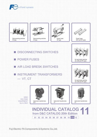
  • 1. Information in this catalog is subject to change without notice. 5-7, Nihonbashi Odemma-cho, Chuo-ku, Tokyo, 103-0011, Japan URL http://www.fujielectric.co.jp/fcs/eng INDIVIDUALCATALOGfromD&CCATALOG20thEdition 11 LOW VOLTAGE PRODUCTS Up to 600 Volts Individual catalog No. 01 Magnetic Contactors and Starters Thermal Overload Relays, Solid-state Contactors 02 Industrial Relays, Industrial Control Relays Annunciator Relay Unit, Time Delay Relays Manual Motor Starters and Contactors Combination Starters Pushbuttons, Selector Switches, Pilot Lights Rotary Switches, Cam Type Selector Switches Panel Switches, Terminal Blocks, Testing Terminals Molded Case Circuit Breakers Air Circuit Breakers Earth Leakage Circuit Breakers Earth Leakage Protective Relays Measuring Instruments, Arresters, Transducers Power Factor Controllers Power Monitoring Equipment (F-MPC) Circuit Protectors Low Voltage Current-Limiting Fuses 03 04 05 06 07 08 09 10 HIGH VOLTAGE PRODUCTS Up to 36kV 11 Disconnecting Switches, Power Fuses Air Load Break Switches Instrument Transformers — VT, CT D&C CATALOG DIGEST INDEX AC Power Regulators Noise Suppression Filters Control Power Transformers 12 Vacuum Circuit Breakers, Vacuum Magnetic Contactors Protective Relays Limit Switches, Proximity Switches Photoelectric Switches 01 02 03 04 05 06 07 08 09 10 11 12 HIGH VOLTAGE EQUIPMENT Up to 36kV INDIVIDUAL CATALOG from D&C CATALOG 20th Edition 11INDIVIDUAL CATALOG from D&C CATALOG 20th Edition 11 DISCONNECTING SWITCHES INSTRUMENT TRANSFORMERS — VT, CT AIR LOAD BRESK SWITCHES POWER FUSES Power fuses HF type Power fuses SCF and HF types Air load break switches LB, LBS and RF types Air load break switches LB, LBS and RF types Instrument transformers CT Instrument transformers VT Disconnecting switches V3 type Disconnecting switches V3 type Instrument transformers ZCT 2010-09 PDF FOLS DEC2011
  • 2. Ha Noi Office: No. 95 - TT4, My Dinh Urban Area, My Dinh, Nam Tu Liem, Hanoi. Tel: (84 4) 3568 3740 Fax: (84 4) 3568 3741 Cambodia Office: #140, Room 1-B, St430, Sangkat Toul Tompuong II, Khan Chamkamon, PP. Tel: 855 2322 3635 Fax: 855 2322 3645 Head Office: No 88, Vinh Phu 40, Hoa Long, Vinh Phu, Thuan An, Binh Duong. Tel: (84 650) 37 37 619 Fax: (84 650) 37 37 620 1800 6547 THINK TOGETHER Nhà phân phối thiết bị điện công nghiệp hàng đầu Việt Nam T
  • 3. Disconnecting Switches V, V3, RF type ................................................................................................11/1 Dimensions.....................................................................................................11/3 Operating mechanism ....................................................................................11/9 Power Fuses General information........................................................................................11/10 Applications ....................................................................................................11/11 General purpose fuses SCF, HF, SCH.........................................................11/17 Back-up fuses JR, HF ...................................................................................11/18 Characteristic curves......................................................................................11/19 Dimensions.....................................................................................................11/22 Air Load Break Switches General information........................................................................................11/26 Accessories/LB type.......................................................................................11/28 Accessories/LBS type ....................................................................................11/29 Dimensions.....................................................................................................11/31 Instrument Transformers VT, CT General information ...................................................................................11/37 Types and ratings ......................................................................................11/39 Dimensions ................................................................................................11/42 ZCT, EVT, special purpose CT General information ...................................................................................11/46 Specifications ............................................................................................11/47 Dimensions ................................................................................................11/48 Page H.V. Disconnecting switches Power fuses, Air load break switches Instrument transformers11
  • 4. MINIMUM ORDERS Orders amounting to less than ¥10,000 net per order will be charged as ¥10,000 net per order plus freight and other charges. WEIGHTS AND DIMENSIONS Weights and dimensions appearing in this catalog are the best information available at the time of going to press. FUJI ELECTRIC FA has a policy of continuous product improvement, and design changes may make this information out of date. Please confirm such details before planning actual construction. INFORMATION IN THIS CATALOG IS SUBJECT TO CHANGE WITHOUT NOTICE.
  • 5. Fuji Electric FA Components & Systems Co., Ltd./D & C Catalog Information subject to change without notice 11/1 11 ■ Type number nomenclature V type/7.2kV H.V. Distribution Equipment Disconnecting switches V and RF-type ■ Description Rated voltage: 7.2 – 36kV Rated current: Up to 4000 Amps Indoor use FUJI high voltage disconnecting switches comprise the V and RF types. The small size and lightness of the V type disconnecting switches make them highly suitable for cubicle use. They make use of FUJI's specially designed coil spring, a line-contact and ball contact (RF type) system which gives them a high efficient operation without overheating. V type disconnecting switches are not provided with latches but their design will not permit them to be opened by magnetic force. Switches provided with latches can also be supplied upon request. ■ Features • 7.2/12/24/36kV, 200 Amps to 4000 Amps • Withstand large momentary current flow • Excellent contact performance • Compact and light in weight • Heavy-duty construction • Stick-operated/gang-operated/motor operated types V-2 V3-2 RF240cI Basic type Rated current 2: 200A 4: 400A 6: 600A 12: 1200A No. of poles Blank: 1-pole Stick-operated type only 3: 3-pole Stick-, manual remote- and motor remote-operated (AC/DC common use) V type/12kV, 24kV Basic type Operating system Blank: Stick-operated G: Manual or motor remote-operated Rated voltage 20: 12/24kV RF240 type No. of poles I: 1-pole III: 3-pole Basic type RF240c III/6/2000 (F-F) Auxiliary switch Blank: Not provided W: Provided Specify the contact arrangement Connection F-F, F-B, B-F, B-B Refer to page 11/3 Operating system Blank: Stick-operated G: Manual remote-operated by R290-B Motor remote-operated by R293B GS: Manual remote-operated by R277 (4000A only) Rated voltage 6: 7.2kV 20:12/24kV 30: 36kV Rated current 600: 600A 1200: 1200A 2000: 2000A 4000: 4000A V - 2 V 3-20/600 No. of poles 3: 3-pole SC-1063 SC-1060 V-1442 ■ Ordering information Specify the following: 1.Type number 2.Rated voltage and current 3.Connection system 4.Operation system 5.Auxiliary contact arrangement ● ● ● Rated current 600: 600A 1200: 1200A
  • 6. Fuji Electric FA Components & Systems Co., Ltd./D & C Catalog Information subject to change without notice11/2 Ratings Connection Voltage Current Short-time withstand (kV) (A) current (kA) 3.6/7.2 200 12.5 (1 sec) *3 Common use 400 12.5 (1 sec) *3 600 12.5 (1 sec) *3 25 (2 sec) *4 1200 31.5 (2 sec) *4 3.6/7.2 200 12.5 (1 sec) *3 Common use 400 12.5 (1 sec) *3 600 12.5 (1 sec) *3 25 (2 sec) *4 1200 31.5 (2 sec) *4 3.6/7.2 2000 32 (2 sec) F-F B-B B-F F-B 3.6/7.2 4000 44 (2 sec) F-F 3.6/7.2 2000 32 (2 sec) F-F B-B B-F F-B 3.6/7.2 4000 44 (2 sec) F-F 12/24 600 22 (2 sec) F-F F-B B-F B-B 12/24 1200 27 (2 sec) F-F F-B B-F B-B 12/24 2000 32 (2 sec) F-F F-B B-F B-B 12/24 4000 44 (2 sec) F-F 12/24 600 22 (2 sec) Common use 1200 27 (2 sec) 12/24 2000 32 (2 sec) F-F F-B B-F B-B 12/24 4000 44 (2 sec) F-F 36 600 22 (2 sec) F-F 1200 27 (2 sec) 2000 32 (2 sec 36 600 22 (2 sec) F-F 1200 27 (2 sec) 2000 32 (2 sec) Type Ordering code V-2 *2 HV3V-200*2 V-4 *2 HV3V-400*2 V-6 *2 HV3V-600*2 V-12*2 HV3V-12X*2 V3-2 HV3W-200 V3-4 HV3W-400 V3-6 HV3W-600 V3-12 HV3W-12X RF240cI/6/2000(F-F) HV3A3-20XA RF240cI/6/2000(B-B) HV3A3-20XB RF240cI/6/2000(B-F) HV3A3-20XD RF240cI/6/2000(F-B) HV3A3-20XC RF240cI/6/4000(F-F) HV3A4-40XA RF240cIII/6/2000(F-F) HV3B3-20XA■*1 RF240cIII/6/2000(B-B) HV3B3-20XB■*1 RF240cIII/6/2000(B-F) HV3B3-20XD■*1 RF240cIII/6/2000(F-B) HV3B3-20XC■*1 RF240cIII/6/4000(F-F) HV3B4-40XA■*3 RF240cI/20/600(F-F) HV3A1-600A RF240cI/20/600(F-B) HV3A1-600C RF240cI/20/600(B-F) HV3A1-600D RF240cI/20/600(B-B) HV3A1-600B RF240cI/20/1200(F-F) HV3A2-12XA RF240cI/20/1200(F-B) HV3A2-12XC RF240cI/20/1200(B-F) HV3A2-12XD RF240cI/20/1200(B-B) HV3A2-12XB RF240cI/20/2000(F-F) HV3A3-20XA RF240cI/20/2000(F-B) HV3A3-20XC RF240cI/20/2000(B-F) HV3A3-20XD RF240cI/20/2000(B-B) HV3A3-20XB RF240cI/20/4000(F-F) HV3A4-40XA V3-20/600 HV7W-600 V3-20/1200 HV7W-12X RF240cIII/20/2000(F-F) HV3B3-20XA■*1 RF240cIII/20/2000(F-B) HV3B3-20XC■*1 RF240cIII/20/2000(B-F) HV3B3-20XD■*1 RF240cIII/20/2000(B-B) HV3B3-20XB■*1 RF240cIII/20/4000(F-F) HV3B4-40XA■*1 RF240cI/30/600 HV3A1-600A RF240cI/30/1200 HV3A2-12XA RF240cI/30/2000 HV3A3-20XA RF240cIII/30/600 HV3B1-600A■*1 RF240cIII/30/1200 HV3B2-12XA■*1 RF240cIII/30/2000 HV3B3-20XA■*1 Auxiliary switch Not available 2NO+2NC sold separately Not available 2NO+2NC to *1 6NO+6NC available on request Not available 2NO+2NC sold separately 2NO+2NC to *1 6NO+6NC available on request Not available 2NO+2NC to *1 6NO+6NC H.V. Distribution Equipment Disconnecting switches V and RF-type ■ Specifications No. of poles 1 3 1 Mass (kg) 1.2 1.2 1.8 2.8 10 10 11 14 22 55 43 43 35 75 170 140 140 120 27 33 33 35 33 36 36 41 32 62 62 70 70 40 45 130 140 140 150 170 34 40 48 135 150 180 3 Note: *1 Auxiliary switch (contact arrangement 2NO+2NC to 6NO+6NC) is available on your request (3-pole only), in this case replace the ■ mark by W and specify required contact arrangement as follow. 2NO + 2NC : W=2A2B, 3NO + 3NC: W=3A3B, 4NO + 4NC: W=4A4B, 6NO + 6NC: W=6A6B *2 When requiring V type with mechanical latch, specify type VS (example VS-2). (Specify L in ordering code.) *3 This conforms to JIS C4606 *4 This conforms to JEC-2310 ■ Auxiliary switches 3-pole V-type disconnecting switches can be fitted with auxiliary switches. The AUX-1 auxiliary switch kits, which are sold separately can easily be fitted on side. In the case of 3-pole RF type disconnecting switches if you order auxiliary switches they will be fitted at the FUJI factory before shipment. When ordering make sure that “W” is suffixed to the type number. Type Contact Use with AUX-1 2NO+2NC V3-2, V3-4, V3-6, V3-12 100/110V DC 15A V3-20 200/220V AC 15A SE-1953 3 1 3 1
  • 7. Fuji Electric FA Components & Systems Co., Ltd./D & C Catalog Information subject to change without notice 11/3 11 ■ Ordering code system, type RF HV 3 A 2–600 A ■ Disconnecting switch Rated voltage 7.2kV: 3 12/24kV: 7 36kV: 8 No. of poles 1 pole: A 3 pole: B Rated current 600A: 1-600 1200A: 2-12X 2000A: 3-20X 4000A: 4-40X ■ Technical data Type V RF240cI/6 V3 RF240cIII/6 RF240cI/20 V3-20 RF240cIII/20 RF240cI/30 RF240cIII/30 No. of poles 1 3 1 3 1 3 Impulse (1.2 × 50µs) (kV) Rated voltage (kV) 7.2 7.2 12/24 12/24 36 36 Dielectric strength (AC rms 1 min.) (kV) To ground 22 22 50 50 70 70 To ground 60 60 125 125 170 170 Between poles 35 35 80 80 110 110 Between poles 70 70 145 145 195 195 ■ Connection Type V, V3 RF240 F-F B-F F-BB-BConnec- tion ■ Dimensions, mm V-2, 4 H.V. Distribution Equipment Disconnecting switches V and RF-type ■ Ordering code system, type V HV 3 V – 200 Disconnecting switch Rated voltage 3: 7.2kV 7: 12/24kV No. of poles V: 1 pole L: 1 pole, type VS W: 3 pole Rated current 200: 200A 400: 400A 600: 600A 12X: 1200A Aux. switch Blank: Not provided W: Provided Specify the contact arrangement, W=2A2B: 2NO+2NC W=3A3B: 3NO+3NC W=4A4B: 4NO+4NC W=6A6B: 6NO+6NC Connection F-F: A B-B: B B-F: D F-B: C V-6 139±5 272±7 6 25 6 187±5 60 1212221±5 ø27 For stick operation 2-ø11 Mounting hole 2-ø11 35 175±5 154±5 278±7 72 6 35 Mounting hole 2-ø11 2-ø17 230±5 ø20 35 2020 6 35 188±5 ø20 4-ø14 156±3 291±7 50 87 8 40252±5401515 2-ø11 Mounting hole 6 V-12
  • 8. Fuji Electric FA Components & Systems Co., Ltd./D & C Catalog Information subject to change without notice11/4 H.V. Distribution Equipment Disconnecting switches RF type ■ Dimensions, mm RF240cI/20, 30/600 (F-F) RF240cI/20, 30/1200 (F-F) RF240cI/6 – 30/2000 (F-F) RF240cI/6, 20/4000 (F-F) i15 a 40 20 4-φ14 4-φ14150 40 175 d c j 170170 42 g 7h b20 20 RF240cI/6/4000 RF240cI/20/4000 Type 390 535 a 350 495 b 139 180 c 95 130 d 305 411 h 155 261 i 570 786 j 190 300 5 6 g a c d j h6 i15 g 80 40 b20 20 20 40 170 170 42 4-φ14 4-φ14 Type RF240cI/6/2000 RF240cI/20/2000 RF240cI/30/2000 390 535 645 a 350 495 605 b 139 180 180 c 95 130 130 d 305 410 500 h i 155 261 351 j 570 786 986 190 300 410 g 5 6 6 b 170 RF240cI/20/600 RF240cI/30/600 Type 545 645 a 505 605 b 335 432 h 269 360 i 685 889 j 300 410 170 5 g 42 42 RF240cI/20/1200 RF240cI/30/1200 Type 545 645 a 505 605 b 376 466 h i 260 350 j 723 923 300 410 g 5 6 20 20 20 20 40 20 40 60h10 130 a Mounting hole 4-ø14 2-ø14 180 i6 j 170 150 h7 i860 j b20 80 130 a Mounting hole 4-ø14 4-ø14 180
  • 9. Fuji Electric FA Components & Systems Co., Ltd./D & C Catalog Information subject to change without notice 11/5 11 ■ Dimensions, mm Gang-operating — V3 type V3-2, V3-4 V3-6 V3-6 V3-12 30 45 ø50 ø53 35 50 20 15 30 40 275 365 6 8 365 370 241 243 a b c d e f g h i H.V. Distribution Equipment Disconnecting switches V type V3-12 3 2-ø11 Auxiliary switch mounting space 470 230±5 50 3.2 12221±512 200 25 15 35 30 6 1416 78 25 45 174 101 150±3 150±3 99 130 15100 124 6 615 360±7 ø13.5 (For R290B) ø13.5 (For R293B) Operating angle 90˚ ø25 (For stick operation) 4-ø12 Mounting hole 90˚ 580 470 362±7 245±5 50 3.2 8 252±540401515 100 1540 1001515 130 150±3 150±3 100 4015 50 4015 45 6 30 200R 25 35 ø13.5 (For R293B) 3 4-ø14 Operating lever Mounting hole 4-ø12Auxiliary switch mounting space ø25 (For stick operation) ø13.5 (For R290B) 470 560 100 45 35 30 130 1001515 150±3 150±3 100 1515 30 6 3 2-ø17 4-ø12 360±7 233±52020 50 303.2 6 240±5 90˚ 200R 2535 ø13.5 (For R293B) Operating lever Mounting holeAuxiliary swich mounting space ø13.5 (For R290B) ø25 (For stick operation) Note : : Mounting hole dimensions
  • 10. Fuji Electric FA Components & Systems Co., Ltd./D & C Catalog Information subject to change without notice11/6 ■ Dimensions, mm V3-20/600 860 100 830 (630) 30 280 35 40 6 4.5 20 150 150 50 364 300 260 110 420 2020 280 1515 50 ø17 4-ø18 Mounting holeAuxiliary switch mounting space H.V. Distribution Equipment Disconnecting switches RF type V3-20/1200 4-ø18 Mounting hole 860 100 (645) 280 280 50 40 8 4.5 1540 150 150 50 364 300 110 507 2020 1515 50 ø14 30830 260 Auxiliary switch mounting space
  • 11. Fuji Electric FA Components & Systems Co., Ltd./D & C Catalog Information subject to change without notice 11/7 11 RF240cIII/30/600 (F-F) RF240cIII/20, 30/1200 (F-F) Terminal 4020 148030 1540 29 30 6 440 425 809 For stick operated type ø40 For remote operated type ø13.2 366 55 6440330 330 60Mounting hole 4-ø19 ø14 720 820 2020 Aux. switch 2NO+2NC, 4NO+4NC: =75 3NO+3NC, 6NO+6NC: =85 40 4020 Terminal b 3030 a 29 6 c g f For stick operated type ø40 For remote operated type ø13.2 h 55 10cd d 80Mounting hole 4-ø19 ø14 e i 2020 Aux. switch 2NO+2NC, 4NO+4NC: =75 3NO+3NC, 6NO+6NC: =85 RF240cIII/20/1200 RF240cIII/30/1200 Type 1160 1540 a 1100 1480 b 340 440 c 240 330 d 630 720 e 690 868 f 376 466 g 266 356 h i 700 780 H.V. Distribution Equipment Disconnecting switches RF type
  • 12. Fuji Electric FA Components & Systems Co., Ltd./D & C Catalog Information subject to change without notice11/8 Type RF240cIII/6/2000 RF240cIII/20/2000 RF240cIII/30/2000 a b c d e f g h i 660 600 200 130 490 557 311 161 640 1160 1100 340 240 630 754 416 266 740 1540 1480 440 330 720 935 506 356 820 RF240cIII/6, 20/4000 (F-F) Type RF240cIII/6/4000 RF240cIII/20/4000 a b c d e f g h i j 920 860 300 160 370 613+_10 380 230 620 59 1280 1220 420 220 530 832+_10 485 335 740 109 b 80 ø14Mounting hole 4-ø19 1540 4020 h e 170 i 2020 3030 d c c d Aux. swicth 2NO+2NC, 4NO+4NC: =75 3NO+3NC, 6NO+6NC: =85 a g f 50 29 6 For stick operated type ø40 For remote operated type ø13.2 Terminal ■ Dimensions, mm RF240cIII/6 – 30/2000 (F-F) d dc c b 150 ø14 Mounting hole 4-ø18 e i 3030 3030 a g For stick operation ø40 For remote operation ø13.5 h15 fj Aux. swicth 2NO+2NC, 4NO+4NC: =35 3NO+3NC, 6NO+6NC: =45 40 Terminal 4020 H.V. Distribution Equipment Disconnecting switches RF type
  • 13. Fuji Electric FA Components & Systems Co., Ltd./D & C Catalog Information subject to change without notice 11/9 11 Gang-operated mechanisms for disconnecting switches ■ Description The V, RF type 3-pole disconnecting switches and the LB type air load break switches can be provided with remote gang-operated mechanisms. The R290-B mechanism is a manual type and is handle-operated. The R293B type is motor driven. An interlocking system prevents incorrect operation. Versions are also available in which locking action is carried out by energizing or de-energizing a solenoid-coil. ■ Features Motor-driven operating mechanism The R293B motor-driven type is provided with an interlocking switch which prevents the motor from being remotely operated when the crank handle is in position. AC and DC common-use motors are available in 110 and 220 Volts ratings. The R293X motorized control devices are easy to install and improve the integrity of the electrical system. R293X devices are sold separately. These mechanisms are provided with manual crank handle so that the disconnecting switch can be operated even if the drive motor is faulty or an electrical interruption has taken place. Units are fitted with SPDT contacts for crank handle operation interlock use — when a switch is being operated manually the drive motor cannot be engaged. Manual operating mechanism The R290-B is a new type manual operating mechanism. The switchgear can be fitted to either side. The crank lever can be attached at any angle through 360°, and this can be easily repositioned for operating convenience. A tie-rod links it to the disconnecting switch. An interlock solenoid coil is provided. An automatic locking mechanism prevents faulty operation. If required a 1NC switch for crank handle operating interlock use can be provided. Please ask FUJI for the installation, dimensions and piping/wiring diagrams. ■ Ordering information Specify the following: 1. Type number • Motor-driven operating mechanism Type R293B-1 R293B-2 R293BH-1 R293BH-2 Application • V-type, RF240-type Rated current 1200A or less • Rated current 2000A • Control unit for motor-driven operating mechanism Type R293X-1 R293X-2 R293X-3 Application R293B-1, R293BH-1 type R293B-2, R293BH-2 type R293B-1, R293BH-1 type • Manual operating mechanism Type R290-B R290-BDS R290-BAS R290Z-BAS Motor driven operating mechanism R293B Contact for crank handle — 1NC (110V DC, 1.3A) 1NC (110V DC, 1.3A) 1NC (110V DC, 1.3A) Note : 24V DC, 48V DC, 200/220V AC are also available. • Switch stick Type HI-10 HI-30 Description • Applicable voltage: Less than 12kV Full length: 1m • Applicable voltage: Less than 36kV Full length: 2m Illustration R290-B D S ■ Type number nomenclature • Manual operating mechanism • Motor driven operating mechanism Contact for crank handle Blank: Without contact S: With contact Interlock coil Blank: Without interlock coil A: AC coil D: DC coil With pin for lock Basic type R290: Unlock-coil energized R290Z: Lock-coil energized R293B-2 Operating voltage 1: 100/110V AC, DC 2: 200/220V AC, DC Basic type • Control equipment R293X-2 Operating voltage 1: 100/110V AC 2: 200/220V AC 3: 100/110V DC Basic type H.V. Distribution Equipment Disconnecting switches Operating mechanism Motor ratings 100/110V AC, DC 8.8A 200/220V AC, DC 4.4A 100/110V AC, DC 8.8A 200/220V AC, DC 4.4A Motor ratings 100/110V AC 200/220V AC 100/110V DC Lock-coil energized — — — 100/110V AC, 0.1A Ordering code HZ1LT-1 HZ1LT-2 Ordering code HZ1LQ-1 HZ1LQ-2 HZ1LQ-3 Ordering code HZ1VG HZ1VH HZ1V1 HZ1VJ Interlock coil Unlock-coil energized — 100/110V DC, 0.1A 100/110V AC, 0.1A — Ordering code HZ1VA SK-599 SH76 Manual operating mechanism R290-B SG-896 Control unit for motor- driven operating mechanism SG-1106
  • 14. Fuji Electric FA Components & Systems Co., Ltd./D & C Catalog Information subject to change without notice11/10 ■ Design features These fuses comply with the require- ments of JEC-2330. The FUJI power fuses fully meet the requirements of the JIS and JEC Standards, which makes them suitable for a wider range of applications. Excellent repeat accuracies FUJI current limiting power fuses have excellent repeat characteristics from the starting current and meet all the requirements of the Standards. This result from the employment of FUJI's specially developed fusible element which maintains its integrity from deterioration for the extent of its long service life. Easy selection The electrical characteristics of the individual transformer, capacitor or motor can easily be matched with the appropriate type from the wide variety of fuses available. Outstanding current limiting characteristics Since the available short-circuit ■ Description FUJI current limiting power fuses are available in general purpose and back-up versions. Type SCF and HF ··· E general purpose fuses will interrupt all excessive current ranging from the minimum melting current to the rated interrupting current. They will accurately interrupt a 200 – 300% overcurrent of the rated current. The fuse can be used independently or incorporated with air load break switches not provided with trip mechanisms. Very economical to install. The back-up fuses are rated at 12kV or higher and used with switches provided with trip mechanisms incorporated with CT or OCR. current is interrupted within half a cycle the thermal and mechanical strength of the equipment can be greatly reduced. Small arc peak voltage The arc peak voltage at the time of interruption is less than twice the rated voltage. This eliminates the possibility of damage to the insulation of the motor winding and other electrical equipment. Wide range interruption The general purpose power fuses SCF and HF ··· E types are capable of interrupting small current overloads in the range of 200% – 300% of their rated current, yet will blow quickly in the face of massive destructive currents. Since they operate without fail through the range of their interrupting capacity they can be used independently and so save construction costs. ■ Construction Fuse link The fusible element consists of a pure silver wire packed in high-purity silica sand in a heat-resisting mechanically strong ceramic barrel. Fuse holder The holder for indoor use uses epoxy resin for insulation and is simple in design. The fuse is easy to replace. The 3-pole holder is provided with the barriers between the poles and the switch is safely operated by stick. Blown fuse indicator (indoor use only, except SCF-6/5) A spring fuse-blown indicator is provided in the fuse ferrule. The indicator is ejected when the fuse is blown. If required the indicator can be fitted with a sensitive switch so that the blown fuse can be identified from a distance. H.V. Distribution Equipment Power fuses General information Fuse link SCF type Single-pole fuse holder SCHA-6 with fuse link Fuse link HF type Single-pole fuse holder HF323 with fuse link Fuse links 36kV HFA 2.5 If10/In 10 15 If0.1/In 35 12 If0.1/In 25 6 If10/In 2 If10/In Melting time-current characteristics Non-melting current Fuse*1 type T M G C 10 <= 7 If10/In If0.1/In The fusible element will not melt when subjected to a current 10 times its rated current for a period of 0.1 seconds one hundred times. The fusible element will not melt when subjected to a current 5 times its rated current for a period of 10 seconds one thousand times. Repeat overcurrent characteristics Note: *1 T: Transformer protection M: Motor protection G: General purpose line protection C: Capacitor protection In: Fuse rated current If10: Current (Amps) where melt in 10 sec. If0.1: Current (Amps) where melt in 0.1 sec. <= <=<=When a fuse is subjected to a current 1.3 times its rated current the fusible element will not melt within two hours. <= 5 <= <= <= < <= ■ Melting time-current characteristics and repeat overcurrent characteristics (JIS C 4604 and JEC-2330) 100 In 0.25 SD-422 SD-423 SD-430 SD-425 300498 SB1068 100 In 0.25 If0.1/In<= 20<= = — — If7,200/In If7,200/In <= 2 3-pole fuse holder SCHIII with fuse links When a fuse is subjected to a current 2. times its rated current the fusible element will not melt within two hours. — If60/In 10<= — The fusible element will not melt when subjected to a current 70 times its rated current for a period of 0.002 seconds one thousand times. If7,200: Current (Amps) where melt in 2 hours. If60: Current (Amps) where melt in 60 sec.
  • 15. Fuji Electric FA Components & Systems Co., Ltd./D & C Catalog Information subject to change without notice 11/11 11 Type HF337E/6/5 HF337E/6/10 HF338E/6/20 HF338E/6/30 HF338E/6/40 HF338E/6/50 HF338E/6/75 HF338E/6/100 HF338E/6/150 HF338E/6/200 *2 HF338E/6/400 *2 Type SCF-6/5 SCF-6/10 SCF-6/20 SCF-6/30 SCF-6/40 SCF-6/50 SCF-6/75 – – – – ■ Type number of fuse • General purpose fuses General purpose fuses and back-up fuses The FUJI current-limiting power fuses are available as either general purpose-types or back-up-types. General purpose fuses are provided with a wide range of interrupting per- formance. They can, for instance, interrupt excessive currents in the 200 – 300% range up to massive short-circuit currents. This indicates that they can interrupt currents including the fuse elements's melting current. Since they are the most reliable type of fuse they can be attached to the FUJI LBS, LB-type air load break switches. They can also be applied independently to H.V. circuits to give them ad- equate overload protection. Back-up fuses are used in coordination with the circuit breaker with trip device, OCR and CT. The OCR operates in the face of small overcurrent approx. 200% of the rated current, while the fuse rapidly interrupts in the face of destructive short-circuit current. Although the power fuse has an excellent performance against massive overcurrent yet it has a tendency to explode against the small overcurrent. There is a region where fusible element melts but interruption may not take place. In this case the circuit breaker is required to cover this region. Nominal current (A) 5 10 20 30 40 50 75 100 150 200 400 3.6kV interrupting capacity (kA) *1 40 (250) 40 (250) 40 (250) 40 (250) 40 (250) 40 (250) 40 (250) 40 (250) 40 (250) 40 (250) 40 (250) Type HF337E/3/5 HF337E/3/10 HF338E/3/20 HF338E/3/30 HF338E/3/40 HF338E/3/50 HF338E/3/75 HF338E/3/100 HF338E/3/150 HF338E/3/200 HF338E/3/400 *2 7.2kV interrupting capacity (kA) *1 40 (500) 40 (500) 40 (500) 40 (500) 40 (500) 20 (250) 20 (250) – – – – 7.2kV interrupting capacity (kA) *1 40 (500) 40 (500) 40 (500) 40 (500) 40 (500) 40 (500) 40 (500) 40 (500) 40 (500) 31.5 (390) 31.5 (390) Notes: *1 ( ) indicate MVA. *2 Back-up fuse Type JR-30/5 HF337/30/10 HFB-30/16 – HFB-30/25 – HFB-30/40 – – 2xHFB-30/40 – – – Type JR-20/5 HF337/20/10 – HF338B/20/20 – HF338B/20/30 HF338B/20/40 – – 2xHF338B/20/40 – – – Nominal current (A) 5 10 16 20 25 30 40 50 75 80 100 150 200 12kV interrupting capacity (kA) *1 40 (830) 40 (830) – 40 (830) – 40 (830) 40 (830) 40 (830) 40 (830) – 40 (830) 40 (830) 40 (830) Type JR-10/5 HF337/10/10 – HF338B/10/20 – HF338B/10/30 HF338B/10/40 HF338B/10/50 HF338B/10/75 – HF338B/10/100 2xHF338B/10/75 2xHF338B/10/100 24kV interrupting capacity (kA) *1 40 (1700) 25 (1000) – 25 (1000) – 25 (1000) 25 (1000) – – 25 (1000) – – – 36kV interrupting capacity (kA) *1 25 (1600) 16 (1000) 32 (2000) – 32 (2000) – 32 (2000) – – 32 (2000) – – – • Back-up fuses Note: *1 ( ) indicate MVA. ■ Repeat operating life of general purpose fuses Transformer circuit Rated Type voltage (kV) 3.6 HF338E/3/100 HF338E/3/150 7.2 SCF-6/30 HF338E/6/30 SCF-6/75 HF338E/6/75 HF338E/6/150 HF338E/6/400 Transformer rated current (A) 75 100 15 15 60 60 100 300 Repeat operations 10000 operations 10000 operations Motor circuit Rated voltage (kV) 3.6 7.2 Type HF338E/3/50 HF338E/3/200 HF338E/3/400 SCF-6/75 HF338E/6/75 HF338E/6/200 HF338E/6/400 Motor rated current (A) 20 100 200 30 30 100 200 Repeat operations 15000 operations 15000 operations Note: Refer to repeat overcurrent characteristics on page 11/10. H.V. Distribution Equipment Power fuses Applications S PF OCR CT When back-up fuse is usedWhen general purpose fuse is used S PF General purpose fuse Time Fuse can interrupt all excessibe current CurrentIn In: Rated current Back-up fuse Circuit is not inerrupted Circuit will be interrupted In Ii Current Characteristic of OCR Time
  • 16. Fuji Electric FA Components & Systems Co., Ltd./D & C Catalog Information subject to change without notice11/12 ■Quick selection guide • 3.3kV oil immersed type transformers 3-phase transformers Rated current (A) 0.88 1.31 1.75 2.63 3.5 4.36 5.25 8.75 13.1 17.5 26.3 35 43.6 52.5 87.5 131 175 Recommended FUJI fuse Type HF337E/3/5 HF337E/3/5 HF337E/3/5 HF337E/3/10 HF337E/3/10 HF338E/3/20 HF338E/3/20 HF338E/3/20 HF338E/3/30 HF338E/3/30 HF338E/3/40 HF338E/3/50 HF338E/3/75 HF338E/3/75 HF338E/3/150 HF338E/3/200 HF338E/3/400 Capacity (kVA) 5 7.5 10 15 20 25 30 50 75 100 150 200 250 300 500 750 1000 Note: Selection based on FUJI standard transformer. • 6.6kV oil immersed type transformers 3-phase transformers Rated current (A) 0.44 0.66 0.88 1.31 1.75 2.19 2.63 4.36 6.55 8.75 13.1 17.5 21.9 26.3 43.6 65.5 87.5 Capacity (kVA) 5 7.5 10 15 20 25 30 50 75 100 150 200 250 300 500 750 1000 Recommended FUJI fuse SCF series Type SCF-6/5 SCF-6/5 SCF-6/5 SCF-6/5 SCF-6/10 SCF-6/10 SCF-6/10 SCF-6/20 SCF-6/20 SCF-6/30 SCF-6/30 SCF-6/40 SCF-6/40 SCF-6/50 SCF-6/75 — — HF series Type HF337E/6/5 HF337E/6/5 HF337E/6/5 HF337E/6/5 HF337E/6/10 HF337E/6/10 HF337E/6/10 HF338E/6/20 HF338E/6/20 HF338E/6/30 HF338E/6/30 HF338E/6/40 HF338E/6/40 HF338E/6/50 HF338E/6/75 HF338E/6/100 HF338E/6/150 • 11kV oil immersed type transformers 3-phase transformers Rated current (A) 0.79 1.05 1.31 1.57 2.62 3.94 5.25 7.87 10.5 13.1 15.8 26.2 39.4 52.5 Recommended FUJI fuse Type JR-10/5 JR-10/5 HF337/10/10 HF337/10/10 HF337/10/10 HF338B/10/20 HF338B/10/20 HF338B/10/30 HF338B/10/30 HF338B/10/40 HF338B/10/40 HF338B/10/50 HF338B/10/75 HF338B/10/100 Capacity (kVA) 15 20 25 30 50 75 100 150 200 250 300 500 750 1000 Note: Selection based on FUJI standard transformer. Note: Selection based on 10Xrated current –0.1 sec. transformer inrush current. Single-phase transformers Capacity (kVA) 5 7.5 10 15 20 25 30 50 75 100 150 200 250 300 500 750 1000 Recommended FUJI fuse Type HF337E/3/5 HF337E/3/10 HF337E/3/10 HF338E/3/20 HF338E/3/20 HF338E/3/20 HF338E/3/20 HF338E/3/30 HF338E/3/50 HF338E/3/75 HF338E/3/100 HF338E/3/100 HF338E/3/100 HF338E/3/150 HF338E/3/200 HF338E/3/400 HF338E/3/400 Rated current (A) 1.52 2.28 3.03 4.55 6.05 7.6 9.1 15.2 22.8 30.3 45.5 60.5 76 91 152 227 303 Single-phase transformers Capacity (kVA) 5 7.5 10 15 20 25 30 50 75 100 150 200 250 300 500 750 1000 Rated current (A) 0.76 1.14 1.51 2.28 3.0 3.8 4.5 7.6 11.4 15.2 22.8 30.3 38 45 76 114 152 Recommended FUJI fuse SCF series Type SCF-6/5 SCF-6/5 SCF-6/10 SCF-6/10 SCF-6/10 SCF-6/20 SCF-6/20 SCF-6/20 SCF-6/40 SCF-6/50 SCF-6/50 SCF-6/75 SCF-6/75 SCF-6/75 — — — HF series Type HF337E/6/5 HF337E/6/5 HF337E/6/10 HF337E/6/10 HF337E/6/10 HF338E/6/20 HF338E/6/20 HF338E/6/20 HF338E/6/40 HF338E/6/50 HF338E/6/50 HF338E/6/75 HF338E/6/75 HF338E/6/75 HF338E/6/100 HF338E/6/200 HF338E/6/200 Single-phase transformers Capacity (kVA) 15 20 25 30 50 75 100 150 200 250 300 500 750 1000 Recommended FUJI fuse Type HF337/10/10 HF337/10/10 HF337/10/10 HF338B/10/20 HF338B/10/20 HF338B/10/20 HF338B/10/30 HF338B/10/40 HF338B/10/40 HF338B/10/50 HF338B/10/75 HF338B/10/75 HF338B/10/100 2xHF338B/10/100 Rated current (A) 1.36 1.82 2.27 2.73 4.55 6.82 9.09 13.6 18.2 22.7 27.3 45.5 68.2 90.9 H.V. Distribution Equipment Power fuses Applications
  • 17. Fuji Electric FA Components & Systems Co., Ltd./D & C Catalog Information subject to change without notice 11/13 11 ■Quick selection guide • 22kV oil immersed type transformers 3-phase transformers Rated current (A) 0.39 0.52 0.66 0.79 1.31 1.97 2.62 3.94 5.25 6.56 7.87 13.1 19.7 29.2 Recommended FUJI fuse Type JR-20/5 JR-20/5 JR-20/5 JR-20/5 HF337/20/10 HF337/20/10 HF337/20/10 HF338B/20/20 HF338B/20/20 HF338B/20/20 HF338B/20/30 HF338B/20/40 HF338B/20/40 2xHF338B/20/40 Capacity (kVA) 15 20 25 30 50 75 100 150 200 250 300 500 750 1000 Note: Selection based on 10Xrated current –0.1 sec. transformer inrush current. Single-phase transformers Capacity (kVA) 15 20 25 30 50 75 100 150 200 250 300 500 750 Recommended FUJI fuse Type JR-20/5 JR-20/5 JR-20/5 HF337/20/10 HF337/20/10 HF338B/20/20 HF338B/20/20 HF338B/20/20 HF338B/20/30 HF338B/20/30 HF338B/20/40 2xHF338B/20/40 2xHF338B/20/40 Rated current (A) 0.68 0.91 1.14 1.36 2.27 3.41 4.55 6.82 9.1 11.4 13.6 22.7 34.1 • 33kV oil immersed type transformers 3-phase transformers Rated current (A) 0.26 0.35 0.44 0.52 0.87 1.31 1.75 2.62 3.5 4.37 5.25 8.75 13.1 17.5 Recommended FUJI fuse Type JR-30/5 JR-30/5 JR-30/5 JR-30/5 JR-30/5 HF337/30/10 HF337/30/10 HF337/30/10 HFB-30/16 HFB-30/16 HFB-30/25 HFB-30/40 2xHFB-30/40 2xHFB-30/40 Capacity (kVA) 15 20 25 30 50 75 100 150 200 250 300 500 750 1000 Note: Selection based on 10Xrated current –0.1 sec. transformer inrush current. Single-phase transformers Capacity (kVA) 15 20 25 30 50 75 100 150 200 250 300 500 750 Recommended FUJI fuse Type JR-30/5 JR-30/5 JR-30/5 JR-30/5 HF337/30/10 HF337/30/10 HFB-30/16 HFB-30/16 HFB-30/25 HFB-30/25 HFB-30/40 2xHFB-30/40 2xHFB-30/40 Rated current (A) 0.45 0.61 0.76 0.91 1.52 2.27 3.03 4.55 6.06 7.6 9.1 15.1 22.2 • 3.3/6.6kV FM-KF type cast-resin transformers 3.3kV Capacity (kVA) 10 20 30 50 75 100 150 200 300 500 3-phase Recommended FUJI fuse Type HF338E/3/20 HF338E/3/20 HF338E/3/20 HF338E/3/30 HF338E/3/40 HF338E/3/40 HF338E/3/50 HF338E/3/75 HF338E/3/100 HF338E/3/150 6.6kV Capacity (kVA) 10 20 30 50 75 100 150 200 300 500 3-phase Recommended FUJI fuse Type SCF-6/20 HF337E/6/20 SCF-6/20 HF338E/6/20 SCF-6/20 HF338E/6/20 SCF-6/20 HF338E/6/20 SCF-6/20 HF338E/6/20 SCF-6/30 HF338E/6/30 SCF-6/40 HF338E/6/40 SCF-6/40 HF338E/6/40 SCF-6/75 HF338E/6/75 HF338E/6/100 Single-phase Recommended FUJI fuse Type HF338E/3/20 HF338E/3/20 HF338E/3/30 HF338E/3/40 HF338E/3/50 HF338E/3/75 HF338E/3/100 HF338E/3/100 HF338E/3/200 Single-phase Recommended FUJI fuse Type SCF-6/10 HF337E/6/10 SCF-6/20 HF338E/6/20 SCF-6/20 HF338E/6/20 SCF-6/30 HF338E/6/30 SCF-6/30 HF338E/6/30 SCF-6/40 HF338E/6/40 SCF-6/50 HF338E/6/50 SCF-6/75 HF338E/6/75 — HF338E/6/100 — Note: Selection based on FUJI standard transformer. H.V. Distribution Equipment Power fuses Applications
  • 18. Fuji Electric FA Components & Systems Co., Ltd./D & C Catalog Information subject to change without notice11/14 H.V. Distribution Equipment Power fuses Applications ■Quick selection guide • Single- and 3-phase oil immersed type transformer connection SC Power fuse ø3 Tr ø1 Tr Notes: 1. Select the rated current of power fuse . 2. These tables are based on the fact that capacity of capacitor (SC) is less than 1/3 of transformer total capacity (kVA) and that the transformer inrush current is 10 × rated current , 0.1 sec. 1ø transformer capacity3ø transform- er capacity 5kVA 5kVA 10kVA 15kVA 20kVA 30kVA 50kVA 75kVA 100kVA 150kVA 7.5kVA 10kVA 15kVA 20kVA 30kVA 50kVA 75kVA 100kVA 1ø transformer capacity3ø transform- er capacity 5kVA 5kVA 10kVA 15kVA 20kVA 30kVA 50kVA 75kVA 100kVA 150kVA 200kVA 250kVA 300kVA 500kVA 7.5kVA 10kVA 15kVA 20kVA 30kVA 50kVA 75kVA 100kVA 3.3kV circuits 6.6kV circuits HF337E /3/5 HF337E /3/10 HF338E /3/30 HF338E /3/40 SCF-6/5 HF337E /6/5 SCF-6/10 HF337E/6/10 SCF-6/ 75 HF338E /6/75 SCF-6/ 40 HF338E /6/40 SCF-6/ 50 HF338E /6/50 SCF-6/50 HF338E/6/50 SCF-6/40 HF338E/6/40 SCF-6/30 HF338E/6/30 SCF-6/20 HF338E/6/20 SCF-6/75 HF338E/6/75 HF338E/6/100 SCF-6/5 HF337E/6/5 HF338E /3/30 HF338E /3/50 HF338E /3/100 HF338E/3/75 HF338E/3/50 HF338E/3/40 HF338E/3/30 HF338E/3/20 HF337E /3/10 HF337E /3/5 HF337E/3/10 HF338E /3/30 HF338E /3/50 Primary fuse protection of transformers (Simple selection method) Series Fuse type SCF-6/5 SCF-6/10 SCF-6/20 SCF-6/30 SCF-6/40 SCF-6/50 SCF-6/75 HF337E/3/5, HF337E/6/5 HF337E/3/10, HF337E/6/10 HF338E/3/20, HF338E/6/20 HF338E/3/30, HF338E/6/30 HF338E/3/40, HF338E/6/40 HF338E/3/50, HF338E/6/50 HF338E/3/75, HF338E/6/75 HF338E/3/100, HF338E/6/100 Maximum current of transformer circuit (A) 1.5 3.2 7.4 13 21 28 46 1.5 3.2 8.2 14 22 30 52 82 SCF HH337E HH338E 1. Selection of the primary fuse, exciting current (r.m.s.) will be determined on the basis of a current 10 times the rated full- load current for the transformer which will flow for 0.1 sec. 2. When a group of three or single-phase transformers is connected in parallel, calculate the IR, IS and IT maximum load line currents of the transformers to determine the largest, and select fuses by use of the table. Fuse Tr ø3 ø1 ø1 IR IS IT
  • 19. Fuji Electric FA Components & Systems Co., Ltd./D & C Catalog Information subject to change without notice 11/15 11 ■Quick selection guide • 3.3kV induction motors H.V. Distribution Equipment Power fuses Applications Motor capacity (kW) 37 55 75 90 110 132 160 200 250 280 315 355 400 450 500 560 630 Squirrel-cage type Rated current (A) 11 15.5 20.6 24 29.1 34.3 41.1 51.1 59.5 68 78.1 86.2 102 114.3 128.7 144.1 162.6 Rush current (A) 73 100 135 157.9 185 215 260.2 320 330 377.2 407 474.1 563 629 703 798 898 Starting time (Sec.) 5 5 5 5 5 5 5 5 10 10 10 10 10 10 10 15 15 Fuse type Normal operating HF338E/3/40 HF338E/3/75 HF338E/3/75 HF338E/3/75 HF338E/3/100 HF338E/3/100 HF338E/3/150 HF338E/3/150 HF338E/3/200 HF338E/3/200 HF338E/3/200 HF338E/3/200 HF338E/3/400 HF338E/3/400 HF338E/3/400 HF338E/3/400 HF338E/3/400 Twice repeat operating HF338E/3/50 HF338E/3/75 HF338E/3/75 HF338E/3/100 HF338E/3/100 HF338E/3/150 HF338E/3/150 HF338E/3/200 HF338E/3/200 HF338E/3/200 HF338E/3/200 HF338E/3/400 HF338E/3/400 HF338E/3/400 HF338E/3/400 HF338E/3/400 — Wound-rotor type Rated current (A) 10.7 15.1 20.1 23.4 28.4 33.5 40.2 49.8 58 66.3 77.6 84.4 100.2 112.3 128.7 144.1 162.6 Rush current (A) 16.1 22.5 30.2 34.9 42.5 50.1 60.1 74.5 86.8 99.2 116.1 126.3 149.9 168 192.6 215.6 243.3 Starting time (Sec.) 17 19 22 23 25 27 30 33 36 38 40 42 44 47 49 52 55 Fuse type Normal operating HF338E/3/20 HF338E/3/20 HF338E/3/30 HF338E/3/30 HF338E/3/40 HF338E/3/40 HF338E/3/50 HF338E/3/75 HF338E/3/75 HF338E/3/100 HF338E/3/100 HF338E/3/100 HF338E/3/150 HF338E/3/150 HF338E/3/200 HF338E/3/200 HF338E/3/200 Twice repeat operating HF338E/3/20 HF338E/3/20 HF338E/3/30 HF338E/3/30 HF338E/3/40 HF338E/3/40 HF338E/3/50 HF338E/3/75 HF338E/3/75 HF338E/3/100 HF338E/3/100 HF338E/3/100 HF338E/3/150 HF338E/3/150 HF338E/3/200 HF338E/3/200 HF338E/3/200 Note: 1. Full load current and starting current values: Motors with ratings of 200kW or less meet the requirements of JEM 1381. Motors with ratings of over 250kW conform to the requirements of FUJI standard motors. 2. Fuse rated values are selected on the basis of G-type fuses. (Please refer to Page 11/10). • 6.6kV induction motors Motor capacity (kW) 250 315 375 450 530 630 750 850 950 1050 1200 1320 1500 Squirrel-cage type Fuse type Normal operating HF338E/6/100 HF338E/6/150 HF338E/6/150 HF338E/6/200 HF338E/6/200 HF338E/6/400 HF338E/6/400 HF338E/6/400 HF338E/6/400 HF338E/6/400 — — — Rated current (A) 29 38 45 54 63 74 89 100 110 121 138 152 172 Twice repeat operating HF338E/6/150 HF338E/6/150 HF338E/6/200 HF338E/6/200 HF338E/6/400 HF338E/6/400 HF338E/6/400 HF338E/6/400 HF338E/6/400 — — — — Note: 1. The application recommendations are based on the ratings for FUJI standard 4-pole motors. 2. The starting current and the starting time differ according to the load GD2 . However, the type of fuse has been selected on the basis of the most typical value. When special operations are involved please contact FUJI. 3. Fuse rated values are selected on the basis of G-type fuses. (Please refer to Page 11/10). Wound-rotor type Fuse type Normal operating SCF-6/40 HF338E/6/40 SCF-6/40 HF338E/6/40 SCF-6/50 HF338E/6/50 SCF-6/75 HF338E/6/75 SCF-6/75 HF338E/6/75 HF338E/6/100 HF338E/6/100 HF338E/6/150 HF338E/6/150 HF338E/6/150 HF338E/6/200 HF338E/6/200 HF338E/6/200 Twice repeat operating SCF-6/40 HF338E/6/40 SCF-6/50 HF338E/6/50 SCF-6/75 HF338E/6/75 SCF-6/75 HF338E/6/75 SCF-6/75 HF338E/6/75 HF338E/6/100 HF338E/6/100 HF338E/6/150 HF338E/6/150 HF338E/6/150 HF338E/6/200 HF338E/6/200 HF338E/6/200 4. When 2-step starting is required please consider the starting time for selecting the fuse: The starting time (i.e., the time before the rated speed is reached) is twice the time taken for 1-step starting. 1 2 time Rated speed 1-step starting(normal starting) Speed Starting time 2-step starting(Twice repeat starting)
  • 20. Fuji Electric FA Components & Systems Co., Ltd./D & C Catalog Information subject to change without notice11/16 ■Quick selection guide • 3.3/6.6kV capacitor Capacity (kVA) 5 7.5 10 15 20 25 30 50 75 100 150 200 250 300 400 500 Rated current (A) 0.88 1.31 1.75 2.62 3.5 4.37 5.25 8.8 13.1 17.5 26.2 35 43.7 52.4 70 87.4 3-phase 3.3kV Fuse type HF337E/3/10 HF337E/3/10 HF337E/3/10 HF338E/3/20 HF338E/3/20 HF338E/3/20 HF338E/3/20 HF338E/3/30 HF338E/3/30 HF338E/3/40 HF338E/3/50 HF338E/3/75 HF338E/3/75 HF338E/3/100 HF338E/3/100 HF338E/3/150 Note: 1. Selection based on the capacitor inrush current of 70 times rated current, 2ms. 2. Fuse rated values are selected on the basis of G-type fuses. (Please refer to Page 11/10). 3-phase 6.6kV Rated current (A) 0.44 0.66 0.88 1.31 1.75 2.2 2.62 4.37 6.56 8.75 13.1 17.5 21.9 26.2 35 43.7 Fuse type SCF-6/5 HF337E/6/5 SCF-6/5 HF337E/6/5 SCF-6/10 HF337E/6/10 SCF-6/10 HF337E/6/10 SCF-6/10 HF337E/6/10 SCF-6/10 HF337E/6/10 SCF-6/20 HF338E/6/20 SCF-6/20 HF338E/6/20 SCF-6/20 HF338E/6/20 SCF-6/30 HF338E/6/30 SCF-6/30 HF338E/6/30 SCF-6/40 HF338E/6/40 SCF-6/50 HF338E/6/50 SCF-6/50 HF338E/6/50 SCF-6/75 HF338E/6/75 SCF-6/75 HF338E/6/75 • 11/22/33kV capacitor Capacity (kVA) 15 20 25 30 50 75 100 150 200 250 300 500 750 1000 Rated current (A) 0.79 1.05 1.31 1.56 2.63 3.94 5.25 7.87 10.5 13.1 15.8 26.3 39.4 52.5 3-phase 11kV Fuse type JR-10/5 JR-10/5 HF337/10/10 HF337/10/10 HF337/10/10 HF338B/10/20 HF338B/10/20 HF338B/10/30 HF338B/10/40 HF338B/10/40 HF338B/10/50 HF338B/10/75 HF338B/10/100 2xHF338B/10/75 3-phase 22kV Rated current (A) 0.39 0.53 0.66 0.79 1.31 1.97 2.63 3.93 5.25 6.55 7.87 13.1 19.7 26.3 Fuse type JR-20/5 JR-20/5 HF337/20/10 HF337/20/10 HF337/20/10 HF338B/20/20 HF338B/20/20 HF338B/20/20 HF338B/20/20 HF338B/20/30 HF338B/20/30 HF338B/20/40 2xHF338B/20/40 — Rated current (A) 0.26 0.35 0.44 0.53 0.88 1.31 1.75 2.63 3.5 4.36 5.25 8.75 13.1 17.5 3-phase 33kV Fuse type JR-30/5 JR-30/5 JR-30/5 JR-30/5 JR-30/5 HF337/30/10 HF337/30/10 HF337/30/10 HFB-30/16 HFB-30/16 HFB-30/16 HFB-30/25 HFB-30/40 2xHFB-30/40 Note: Selection based on the capacitor inrush current, 70 times rated current –2ms. H.V. Distribution Equipment Power fuses Applications
  • 21. Fuji Electric FA Components & Systems Co., Ltd./D & C Catalog Information subject to change without notice 11/17 11 H.V. Distribution Equipment Power fuses & fuse holders 3.6 and 7.2kV Ratings Voltage (kV) 7.2 3.6 7.2 Note: * Back up fuse. SCF-6/30 30A HF337E/3/10 10A HF338E/3/100 100A HF338E/6/400 400A ■Quick selection guide General purpose fuses • Fuse-link Illustration • Fuse-holder Rated voltage (kV) 3.6/7.2 3.6/7.2 7.2 Illustration Note: Mass does not include fuse-link. * With porcelain insulator. SCHIII-6 Interrupting capacity (kA) 40 (500MVA) 20 (250MVA) 40 (250MVA) 40 (500MVA) 31.5 (390MVA) Usage Indoor use Outdoor use Indoor use Current (A) 5 10 20 30 40 50 75 5 10 20 30 40 50 75 100 150 200 400 5 10 20 30 40 50 75 100 150 200 400 Poles 1 1 1 3 3 1 1 1 1 3 Type SCF-6/5 SCF-6/10 SCF-6/20 SCF-6/30 SCF-6/40 SCF-6/50 SCF-6/75 HF337E/3/5 HF337E/3/10 HF338E/3/20 HF338E/3/30 HF338E/3/40 HF338E/3/50 HF338E/3/75 HF338E/3/100 HF338E/3/150 HF338E/3/200 HF338E/3/400* HF337E/6/5 HF337E/6/10 HF338E/6/20 HF338E/6/30 HF338E/6/40 HF338E/6/50 HF338E/6/75 HF338E/6/100 HF338E/6/150 HF338E/6/200* HF338E/6/400* Type HF340/6a HF340/6b HF323/6e HF340III/6a HF340III/6b HF326C/6a HF326C/6b HF326CII/6b SCHA-6 SCHIII-6 Ordering code HF2S-005 HF2S-010 HF2S-020 HF2S-030 HF2S-040 HF2S-050 HF2S-075 HF1A-005 HF1A-010 HF1E-020 HF1E-030 HF1E-040 HF1E-050 HF1E-075 HF1E-100 HF1E-150 HF1E-200 HF1E-400 HF2A-005 HF2A-010 HF2E-020 HF2E-030 HF2E-040 HF2E-050 HF2E-075 HF2E-100 HF2E-150 HF2E-200 HF2E-400 Ordering code HE3E HE3F HE3U HE3P HE3Q HE3R HE3K HE3L HE3S HE3T Mass (kg) 1.3 1.3 1.3 1.3 1.3 1.5 1.5 1.0 1.0 2.5 2.5 2.5 2.5 2.5 2.5 4.0 4.0 6.5 1.0 1.0 2.5 2.5 3.0 3.0 3.0 3.0 3.0 3.0 6.5 Applicable fuse-holder Indoor use Type SCHA-6 SCHIII-6 HF340/6a HF340III/6a HF340/6b HF340III/6b HF323/6e HF340/6a HF340III/6a HF340/6b HF340III/6b HF323/6e Outdoor use Type — HF326C/6a HF326C/6b — HF326C/6a HF326C/6b — Mass (kg) 3.0 3.5 16.5* 7.0 8.0 21.5* 22.0* 24.0* 3.3 7.0 SD-423 SD-424 SD-425 SD-422 HF SD-428
  • 22. Fuji Electric FA Components & Systems Co., Ltd./D & C Catalog Information subject to change without notice11/18 ■ Type number nomenclature • Fuse-link SCF - 6/5 Rated current 5: 5A 10: 10A 20: 20A 30: 30A 40: 40A 50: 50A 75: 75A Rated voltage 6: 7.2kV Basic type HF337E / 6 /10 Rated current 5: 5A 75: 75A 10: 10A 100: 100A 20: 20A 150: 150A 30: 30A 200: 200A 40: 40A 400: 400A 50: 50A Rated voltage 3: 3.6kV 10: 12kV 6: 7.2kV 20: 24kV 30: 36kV Basic type HF337E General purpose HF338E fuse HF337 HF338B Back-up fuse JR Applicable fuse-holderMass (kg) 1.0 1.5 3.0 3.0 3.0 3.0 3.0 3.0 6.0 6.0 1.5 2.0 3.5 3.5 3.5 7.0 2.0 2.5 4.6 6.8 6.8 13.6 ■ Types and ratings Back-up fuses (Rated minimum breaking current: 3 × Rated current) • Fuse-link Illustration Indoor use Type JT-10Z HF323/10a HF323/10b HF323II/10b JT-20Z HF323/20 HF323II/20 JT-30Z HF323/30 HF323II/30 Outdoor use Type — HF326/10a HF326/10b HF326II/10b — HF326/20 HF326II/20 — HF326/30 HF326II/30 Fuse link 36kV Interrupting capacity (kA) 40 (830MVA) 40 (1700MVA) 25 (1000MVA) 25 (1600MVA) 16 (1000MVA) 32 (2000MVA) Current (A) 5 10 20 30 40 50 75 100 150 200 5 10 20 30 40 80 5 10 16 25 40 80 Ratings Voltage (kV) 12 24 36 Type JR-10/5 HF337/10/10 HF338B/10/20 HF338B/10/30 HF338B/10/40 HF338B/10/50 HF338B/10/75 HF338B/10/100 2xHF338B/10/75 2xHF338B/10/100 JR-20/5 HF337/20/10 HF338B/20/20 HF338B/20/30 HF338B/20/40 2xHF338B/20/40 JR-30/5 HF337/30/10 HFB-30/16 HFB-30/25 HFB-30/40 2xHFB-30/40 Ordering code HF4J-005 HF4Q-010 HF4D-020 HF4D-030 HF4D-040 HF4D-050 HF4D-075 HF4D-100 HF4D-075 HF4D-100 HF6J-005 HF6Q-010 HF6D-020 HF6D-030 HF6D-040 HF6D-080 HF8J-005 HF8Q-010 HF8H-016 HF8H-025 HF8H-040 HF8H-080 Mass (kg) 17 18 20 21 23 25 23 25 31 33 30 32 41 43 • Fuse-holder Illustration Note: Mass does not include fuse-link. HF323/10 ■ Ordering information Specify the following: 1. Type number 2. Rated voltage 3. Rated current When ordering fuse-holder (HF type indoor use) with remote operation indicating device, add “S” to the end of type number. Example · Fuse-link 7.2kV HF-type general purpose fuse. Rated current 100A Interrupting capacity 40kA Type number: HF338E/6/100 · Fuse-holder (for above fuse-link) 7.2kV 100A Single-pole Indoor use Type number: HF340/6b Rated voltage (kV) 12 24 36 Usage Indoor use Outdoor use Indoor use Outdoor use Indoor use Outdoor use Poles 1 1 1 1 1 1 Type HF323/10a HF323/10b HF323II/10b HF326/10a HF326/10b HF326II/10b HF323/20 HF323II/20 HF326/20 HF326II/20 HF323/30 HF323II/30 HF326/30 HF326II/30 Ordering code HE4E HE4E-S HE4E-L HE4R HE4K HE4L HE6M HE6G HE6N HE6L HE8M HE8G HE8N HE8L       • Fuse-holder SCHA - 6 Rated voltage 6: 7.2kV Basic type SCHA: Single-pole SCHIII: 3-pole HF340 III / 6 Rated voltage 6: 7.2kV 10: 12kV 20: 24kV 30: 36kV Poles Blank: Single-pole II: 2-pole parallel connected III: 3-pole Basic type HF340: Indoor use HF323: Indoor use HF326: Outdoor use H.V. Distribution Equipment Power fuses & fuse holders 12, 24, and 36kV SB-1068 300498
  • 23. Fuji Electric FA Components & Systems Co., Ltd./D & C Catalog Information subject to change without notice 11/19 11 H.V. Distribution Equipment Power fuses 3.6 and 7.2kV ■ Characteristic curves • General purpose fuses Current-limiting characteristic curves SCF-type 7.2kV HF-type 3.6 / 7.2kV (E type) 1 0.1 0.2 0.3 0.5 0.8 1 2 3 5 8 10 20 30 50 80 100 0.1 0.2 0.3 0.4 0.5 0.6 0.8 10 20 30 40 50 60 80 100 2 3 4 5 6 8 SCF-6/75 B A SCF-6/50 SCF-6/40 SCF-6/30 SCF-6/20 SCF-6/10 SCF-6/5 Max.let-throughcurrent(kApeak) Available current (eff) kA 2.0√— 2 lsw1.0√— 2 lsw 1 0.1 0.2 0.3 0.5 0.8 1 2 3 5 8 10 20 30 50 80 100 0.1 0.2 0.3 0.4 0.5 0.6 0.8 2 3 4 5 6 8 10 20 30 40 50 60 80 100 HF338E/3 6/400 HF338E/3 6/200 HF338E/3 6/150 HF338E/3 6/100 HF338E/3 6/75 HF337E/3 6/5 HF337E/3 6/10 HF338E/3 6/20 HF338E/3 6/30 HF338E/3 6/50 HF338E/3 6/40 B A Max.let-throughcurrent(kApeak) Available current (eff) kA 2.0√ — 2 lsw 1.0√ — 2 lsw Permissible time-current characteristic curves SCF-type 7.2kV HF-type 3.6 / 7.2kV (E type) 0.01 0.02 0.03 0.04 0.05 0.1 0.2 0.3 0.4 0.5 1.0 2.0 3.0 4.0 5.0 10 20 30 40 50 60 SCF-6/5 SCF-6/10 SCF-6/20 SCF-6/30 SCF-6/40 SCF-6/50 SCF-6/75 100 200 300 400 500 1000 10000 2000 3000 4000 5000 5 10 100 1000 10000 1 2 4 6 8 10 15 20 30 40 2 1 Time(sec.) (min)(h) Current [A] 0.01 0.02 0.03 0.04 0.05 0.1 0.2 0.3 0.4 0.5 1.0 2.0 3.0 4.0 5.0 10 20 30 40 50 60 HF337E/3 6/5 HF338E/3 6/10 HF338E/3 6/20 HF338E/3 6/30 HF338E/3 6/40 HF338E/3 6/50 HF338E/3 6/75 HF338E/3 6/100 HF338E/3 6/150 HF338E/3 6/200 HF338E/3 6/400 100 200 300 400 500 1000 10000 2000 3000 4000 5000 5 10 100 1000 10000 1 2 4 6 8 10 15 20 30 40 2 1 Time(sec.) (min)(h) Current [A]
  • 24. Fuji Electric FA Components & Systems Co., Ltd./D & C Catalog Information subject to change without notice11/20 Total clearing (operating ) time-current characteristic curves SCF-type 7.2kV HF-type 3.6 / 7.2kV (E type) Melting time-current characteristic curves (Pre-arcing) SCF-type 7.2kV HF-type 3.6 / 7.2kV (E type) H.V. Distribution Equipment Power fuses 3.6 and 7.2kV • General purpose fuses 0.01 0.02 0.03 0.04 0.05 0.1 0.2 0.3 0.4 0.5 1.0 2.0 3.0 4.0 5.0 10 20 30 40 50 60 SCF-6/5 SCF-6/10 SCF-6/20 SCF-6/30 SCF-6/40 SCF-6/50 SCF-6/75 100 200 300 400 500 1000 10000 2000 3000 4000 5000 5 10 100 1000 10000 1 2 4 6 8 10 15 20 30 40 2 1 (min)(h) Time(Sec.) Current(Amps) 0.01 0.02 0.03 0.04 0.05 0.1 0.2 0.3 0.4 0.5 1.0 2.0 3.0 4.0 5.0 10 20 30 40 50 60 HF337E/3 6/5 HF337E/3 6/10 HF338E/3 6/20 HF338E/3 6/30 HF338E/3 6/40 HF338E/3 6/50 HF338E/3 6/75 HF338E/3 6/100 HF338E/3 6/150 HF338E/3 6/200 HF338E/3 6/400 100 200 300 400 500 1000 10000 2000 3000 4000 5000 5 10 100 1000 10000 1 2 4 6 8 10 15 20 30 40 2 1 (min)(h) Time(Sec.) Current(Amps) 0.01 0.02 0.03 0.04 0.05 0.1 0.2 0.3 0.4 0.5 1.0 2.0 3.0 4.0 5.0 10 20 30 40 50 60 SCF-6/5 SCF-6/10 SCF-6/20 SCF-6/30 SCF-6/40 SCF-6/50 SCF-6/75 100 200 300 400 500 1000 10000 2000 3000 4000 5000 5 10 100 1000 10000 1 2 4 6 8 10 15 20 30 40 2 1 (min)(h) Time(Sec.) Current(Amps) HF338E/3 6/75 HF338E/3 6/400 0.01 0.02 0.03 0.04 0.05 0.1 0.2 0.3 0.4 0.5 1.0 2.0 3.0 4.0 5.0 10 20 30 40 50 60 HF337E/3 6/5 HF337E/3 6/10 HF338E/3 6/20 HF338E/3 6/30 HF338E/3 6/40 HF338E/3 6/50 HF338E/3 6/100 HF338E/3 6/150 HF338E/3 6/200 100 200 300 400 500 1000 10000 2000 3000 4000 5000 5 10 100 1000 10000 1 2 4 6 8 10 15 20 30 40 2 1 (min)(h) Time(Sec.) Current(Amps)
  • 25. Fuji Electric FA Components & Systems Co., Ltd./D & C Catalog Information subject to change without notice 11/21 11 ■ Characteristic curves • Back-up fuses Current-limiting characteristic curves HF-type 12, 24kV HFB-type 36kV H.V. Distribution Equipment Power fuses 12, 24, and 36kV Melting time-current characteristic curves HF-type 12, 24kV HFB-type 36kV Total clearing (operating) time-current characteristic curves HF-type 12, 24kV HFB-type 36kV 0.3 0.5 1 3 5 10 30 50 100 100 50 30 10 5 3 1 0.5 0.3 0.1 (G) 5A 10A 20A 30A 40A 50A 75A 100A 2 Isw 2 Isw 2 Max.let-throughcurrent(kApeak) Available current (eff) kA 0.1 0.30.5 1 3 5 10 30 50 100 0.1 0.3 100 50 30 10 5 3 1 0.5 25A 16A 40A 2 Isw 2 Isw 2 Max.let-throughcurrent(kApeak) Available current (eff) kA 1 2 3 4 106 8 20 3040 10060 300200 500 1000 2000 3000 5000 10000 0.01 0.02 0.04 0.1 0.06 0.2 0.4 1 0.6 2 4 10 6 20 40 2 4 10 20 60 120 6 1 SecondMinute 5A 10A 20A 30A 40A 50A 75A 100A Time Current (Amps) 1 2 3 4 106 8 20 3040 10060 300200 500 1000 2000 3000 5000 10000 0.01 0.02 0.04 0.1 0.06 0.2 0.4 1 0.6 2 4 10 6 20 40 2 4 10 20 60 120 180 240 6 1 SecondMinute 40A 25A 16A Time Current (Amps) 1 2 3 4 106 8 20 30 40 10060 0.01 0.02 0.04 0.1 0.06 0.2 0.4 1 0.6 2 4 10 6 20 40 2 4 10 20 60 120 180 240 6 1 SecondMinute Time Current (Amps) 1 2 3 4 106 8 20 3040 10060 300200 500 1000 2000 3000 5000 10000 0.01 0.02 0.04 0.1 0.06 0.2 0.4 1 0.6 2 4 10 6 20 40 2 4 10 20 60 120 6 1 SecondMinute 5A 10A 20A 30A 40A 75A 100A 50A Time Current (Amps) 1 2 3 4 106 8 20 30 40 10060 0.01 0.02 0.04 0.1 0.06 0.2 0.4 1 0.6 2 4 10 6 20 40 2 4 10 20 60 120 180 240 6 1 Second Time Minute Current (Amps) 1 2 3 4 106 8 20 3040 10060 300200 500 1000 2000 3000 5000 10000 0.01 0.02 0.04 0.1 0.06 0.2 0.4 1 0.6 2 4 10 6 20 40 2 4 10 20 60 120 180 240 6 1 SecondMinute 40A 25A 16A Time Current (Amps) 0.1 0.3 0.5 1 3 5 10 30 50 100 0.01 0.1 0.3 0.5 1 3 5 Max.let-throughcurrent(kApeak) 5A 2 Isw 2 Isw 2 Available current (eff) kA JR-type 36kV JR-type 36kV JR-type 36kV
  • 26. Fuji Electric FA Components & Systems Co., Ltd./D & C Catalog Information subject to change without notice11/22 H.V. Distribution Equipment Fuse holders SCH & HF340 type ■ Dimensions, mm (with fuse links) • General purpose fuses Fuse-holder SCHA-6 SCH III-6 HF-340/6a HF340 III/6a HF340/6b HF340 III/6b 40 60 85 110 85 12 280 376 Mounting hole 2-ø14 Fuse link 2-ø11 246 6 77 77 29 222 29 30 6 110414 295 77 77 12 376 Mounting hole 4-ø14 Fuse link Insulation barrier Epoxyresin insulator 246 274 116 6 51.5 222 295 325 51.5 1515 30 414 160160 415 3652525 40 3 40 47.547.5 130 6-ø11 40 60 85 85 12 280 376 Mounting hole 2-ø14 241 6 77 77 29 222 280 29 30 110 6 419 2-ø11 110 Fuse link 77 77 12 376 241 274 116 6 51.5 222 295 325 51.5 1515 30 419 160160 415 2525 3 40 47.547.5 130 40 6-ø11 295 Mounting hole 4-ø14 Fuse link Insulation barrier Epoxyresin insulator 365 40 60 Mounting hole 2-ø14 85 85 12 380 476 2-ø11 241 6 77 77 29 322 380 29 30 110 6 519 210 Fuse link 77 77 12 476 241 274 116 6 51.5 322 395 425 51.5 1515 30 519 160160 415 2525 3 40 47.547.5 130 40 395 6-ø11 Mounting hole 4-ø14 Fuse link Insulation barrier Epoxyresin insulator 365
  • 27. Fuji Electric FA Components & Systems Co., Ltd./D & C Catalog Information subject to change without notice 11/23 11 ■ Dimensions, mm (with fuse links) • General purpose fuses Fuse-holder HF323/6e H.V. Distribution Equipment Fuse holders HF323 & HF326 type HF326C/6a, 6b HF326C II/6b Installation dimensions (minimum) Usage Rated Fuse-holder Dimensions, mm voltage Type Between poles To ground (kV) (X) (X1) Indoor use 7.2 SCHA-6 160 110 3.6 HF340/6a 160 130 HF340/6b 160 100 2×HF340/6b 260 210 HF323/6e 250 175 7.2 HF340/6a 160 130 HF340/6b 160 130 2×HF340/6b 260 210 HF323/6e 250 175 Outdoor use 3.6 HF326C/6a 200 130 HF326C/6b 200 130 HF326CII/6b 290 170 7.2 HF326C/6a 230 150 HF326C/6b 230 150 HF326CII/6b 320 190 20 560 52020 20 100130 105 350 105 Mounting hole 4-ø142-ø11 145 95 50 150 369 1626 5 155105 711 12 92 360 192 80 40 ø12 115 30 ø125 5050 12 432 15 15 12 HF326C/6a=198 HF326C/6b=298 HF326C/6b=622 HF326C/6a=522 100 272 100 442 472 92 4 Mounting hole 4-ø12 360 18030 ø125 298 298 122-ø12 4-ø12 10010015 15442 472 62280 115 200max. 9292 8 X1 X X X1
  • 28. Fuji Electric FA Components & Systems Co., Ltd./D & C Catalog Information subject to change without notice11/24 Fuse-holder Rated voltage Rated current a b c e f g h j m n Type (kV) (A) HF323/10a 12 10 608 568 388 105 155 317 185 776 160 140 HF323/10b 12 20 to 100 758 718 538 105 155 317 185 926 160 140 HF323II/10b 12 150, 200 758 718 538 105 155 317 185 926 111 111 HF323/20 24 10 to 40 788 748 538 130 180 394 260 1001 130 106 HF323II/20 24 80 788 748 538 130 180 394 260 1001 111 111 HF323/30 36 10 to 40 884 844 634 130 180 484 350 1186 130 106 HF323II/30 36 80 884 844 634 130 180 484 350 1186 111 111 H.V. Distribution Equipment Fuse holders HF323 & HF326 type ■ Dimensions, mm • Back-up fuses (12, 24 and 36kV) Fuse-holder HF323 HF323 II Fuse-holder Rated voltage Rated current a b c d e f g Type (kV) (A) HF326/10a 12 10 628 588 388 433 309 8 900 HF326/10b 12 20 to 100 778 738 538 433 309 8 1050 HF326II/10b 12 150, 200 778 738 538 433 409 6 1050 HF326/20 24 10 to 40 778 738 538 568 444 8 1185 HF326II/20 24 80 778 738 538 568 444 6 1185 HF326/30 36 10 to 40 874 814 638 698 574 8 1410 HF326II/30 36 80 874 814 638 698 574 6 1410 HF326 HF326 II 640 40 15 Terminal m g8 he f e f 40 (35) 6 (8) j nc b 40 15 2-ø14 (1-ø14)Terminal Mounting hole 4-ø14 ( ):24,36kV a b a Terminal 2-ø14 for 12kV 1-ø14 for 24/36kV Terminal 2-ø14 for 12kV 1-ø14 for 24/36kV Mounting hole 4-ø14 ø14 b Mounting hole 4-ø15 Mounting hole 4-ø15 c 152 40 15 Terminal ø14 162 d a 85 125 b a 85 406 125 173 fe 358 g 40 20 Terminal ø14
  • 29. Fuji Electric FA Components & Systems Co., Ltd./D & C Catalog Information subject to change without notice 11/25 11 H.V. Distribution Equipment Power fuses Fuse-links ■ Dimensions, mm General purpose fuses 3.6, 7.2kV Type L max. Dimensions, mm SCF-6/5 SCF-6/10 SCF-6/20 SCF-6/30 SCF-6/40 SCF-6/50 SCF-6/75 274 274 HF337E/6/5 HF337E/6/10 262 HF338E/6/20 HF338E/6/30 HF338E/6/40 to HF338E/6/200* HF338E/6/400* 266 366 408 HF337E/3/5 HF337E/3/10 HF338E/3/20 to HF338E/3/100 HF338E/3/150 HF338E/3/200 HF338E/3/400* 262 266 366 408 *: Back-up fuse Mass: See page 11/18. ■ Ordering information: See page 11/18. Type L max. Dimensions, mm 362 HF337/20/10 HF337/30/10 607 512 HF338B/10/20 HF338B/10/30 HF338B/10/40 HF338B/10/50 HF338B/10/75 HF338B/10/100 HF338B/20/20 HF338B/20/30 HF338B/20/40 516 HFB-30/16 HFB-30/25 HFB-30/40 603 Mass: See page 11/18. HF337/10/10 JR-10/5 262 JR-20/5 362 JR-30/5 512 Back-up fuses ø52 ø58 6 L 35 ø58 ø58 6 L 35 ø48 ø45 ø56 35 L ø77 ø45 ø85 37 L ø98 ø108 55 L ø48 ø45 ø56 35 L ø77 ø45 ø85 37 L ø88 ø45 ø96 37 L ø98 ø108 55 L L 35 ø45 ø48 ø56 L 26 37 ø45 ø77 ø85 L 33 ø45 16Aø75 25A 40A ø94 16Aø69 25A 40A ø88 L 35 ø45 ø48 ø56
  • 30. Fuji Electric FA Components & Systems Co., Ltd./D & C Catalog Information subject to change without notice11/26 H.V. Distribution Equipment Air load break switches General information ■ Description 3.6/7.2kV, 100–600 Amps (LB) 3.6/7.2kV, 200 Amps (LBS) 12/24/36kV, 600–1200 Amps (RF) FUJI air load break switch type LBS is provided with current limiting power fuses and type LB is not so fitted. Both types are compact and incorporate arc-extinguishing devices of FUJI's own design. The arc is drawn into a long narrow chamber with close clearances in which the gases are rapidly cooled and dispersed. Contact points therefore wear very slowly, so giving switches a long service life. FUJI air load break switches are recommended for use with power capacitors and transformers. ■ Features Excellent arc-extinguishing characteristics The arc-extinguishing system uses a gas-cooling method. This results in less contact wear than that of comparable oil-immersed types, so ensuring a longer service life and lower maintenance costs. Light and compact design The load break switch and fuses are incorporated into one body and are ideally suited for H.V. cubicle or metal- clad switchgear assembly applications. High current-limiting power fuses The LBS type is provided with FUJI power fuses so ensuring an accurate and uniform interrupting performance. Economical first cost The use of these fuses eliminates the need for circuit breakers with trip mechanisms, and so reduces initial installation costs. Safe fuse replacement Fuses can easily be replaced or changed to different ratings in perfect safety. A shunt trip mechanism A trip mechanism can be attached to LBS and LB having 100 and 200 Amps ratings. It can be tripped remotely. Blown fuse indicator LBS and LB200 to 400 Amps rated switches can be supplied with a blown indicator limit switch attached for remote indication use. Auxiliary contacts All these switches can be attached with 2NO+2NC 15 Amps switches. Motor-driven-types available The standard versions are for stick operation. Motor-driven versions are also available. For further details please contact FUJI. ■ LB type 3.6kV/7.2kV up to 600 Amps 3-pole 3.6kV/7.2kV 200 and 400 Amps 3-pole with power fuse The LB-type air load break switches are provided with the following major features: 1. They have been down-sized so that they can be installed in compact cubicles. 2. An improved interrupting performance and greater operating safety, achieved through a rotating arc contact and redesigned arc chute. 3. Accessories are built using a modular system, so that power fuse frames, gang-operated mechanisms and auxiliary swithches can easily be added to the main switch body as required. These can be fitted in position on site without adjustment. In addition, the shunt trip mechanism (f) can be incorporated into the basic frame. Previously they were regarded as accessories. If shunt trip is required f suffix should be added to the type number when ordering. Shunt trip mechanisms are factory-fitted before shipment. Please note that the R290B or R293B remote gang-operated mechanism cannot be incorporated with these shunt trip mechanisms. Those LB- type air load break switches of 200AF and 400AF can be fitted with power fuses. However, even if the LB-type units have 400AF ratings, power fuses up to 200 Amps only are required. LB types SG-882 SG-884 SG-877 ■ LBS-type 3.6/7.2kV, 200 Amps 3-pole The LBS is an air load break switch with attached power fuses. A striker is incorporated into this unit, a feature which is not found in conventional load break switches. The striker is a trip mechanism which operates the moment the fuse blows. When this occurs the striker causes all 3- pole to open at the same time. If air load break switches do not have this striker feature it is possible for some of the phases to remain alive after the fuse has blown, so resulting in a dangerous situation. This FUJI feature adds to the safety of the electrical system. As LBS-type air load break switches are provided with a built-in auto trip mechanism the R290B and R293B remote gang- operated mechanisms cannot be fitted. ■ RF-type 12/24/36kV up to 1200 Amps 3-pole The RF-type load break switch consists of a main blade, an auxiliary blade and an arc chute. The auxiliary blade is located at the arc chute and connected with the main blade. It will make contact at the same time as the main blade. The auxiliary blade will be momentarily held in contact in the arc chute at the time when the main blade opens. Once the main blade has reached the limit of travel the auxiliary blade will rapidly return to its position against the main blade under the influence of stored energy in the spring. This quick-break device functions effectively even when manually operated, and since the contact moves at high speed the arc is rapidly elongated and gas-cooled in the arc chute. LBS type SP-304 RF type SE-292
  • 31. Fuji Electric FA Components & Systems Co., Ltd./D & C Catalog Information subject to change without notice 11/27 11 H.V. Distribution Equipment Air load break switches General information ■ General specification of switch body LBS type LB type Description LBS-6/200 LBS-6/210 without shunt trip device with shunt trip device LBS-6/200f LBS-6/210f LB-6/100 LB-6/200 LB-6/400 LB-6/600 LB-6/100f LB-6/200f Rated Voltage (kV) 7.2/3.6 7.2/3.6 7.2/3.6 7.2/3.6 7.2/3.6 7.2/3.6 7.2/3.6 7.2/3.6 Current (A) 200 200 100 200 400 600 100 200 Short-time current (1 sec.) (kA) – – 4 8 12.5 8 4 4 Making short-circuit current (kA) – – 10 20*1 31.5*1 20*1 10 10 Frequency (Hz) 50/60 50/60 50/60 50/60 50/60 50/60 50/60 50/60 Insulation Dielectric strength (1 minute) (kV) 22 22 22 22 22 22 22 22 BIL (1.2 × 50µs) (kV) 60 60 60 60 60 60 60 60 Main active load breaking capacity (A) 200 200 100 200 400 200 100 200 Cable charging breaking capacity (A) 10 10 10 10 10 10 10 10 Transformer off load breaking capacity (A) 10 10 5 10 20 10 5 10 Capacitor breaking current (A) 30 30 30 30 50 30 30 30 Fuse Holder with blown indicator – – – FH-2 FH-2 – – FH-2 Holder without blown indicator – – – FH-1 FH-1 – – FH-1 Link JC-6*4 JC-6*5 – HF337E HF337E – – HF337E – HF338E HF338E*2 – HF338E Interrupting capacity (kA) 40 40 – 40*3 40*3 – – 40*3 Description RF250 type RF248 type RF250III/ RF248III/ RF248III/ RF248III/ 20/600 20/600 20/1200 30/600 Rated Voltage (kV) 12/24 12/24 12/24 36 Current (A) 600 600 1200 600 Short-time current (1 sec.) (kA) 22 22 27 22 Making short-circuit current (kA) 40 40 40 40 Frequency (Hz) 50/60 50/60 50/60 50/60 Insulation Dielectric strength (1 minute) (kV) 50 50 50 70 BIL (1.2 × 50µs) (kV) 125 125 125 170 Main active load breaking capacity (A) 600 75 75 50 Cable charging breaking capacity (A) 20 20 20 15 Transformer off load breaking capacity (A) 20 10 10 10 Closing loop breaking capacity (A) 600 75 75 50 Note: *1 : 20kA when operated by R290-B. *2 : 200A is maximum for fuse-link. *3 : 31.5kA when 200A power fuse is used at 7.2kV. 10kA when operate by R293B. *4 : 75A is maximum for fuse-link. *5 : 100A is maximum for fuse-link. LBS and LB types ■ Construction Arc extinguishing chute FUJI new LBS and LB type airload break switches are compact and have superior safety characteristics. This is mainly due to the newly-developed arc extinguishing chamber. ■ Features 1. The arc extinguishing chute is so designed that it is enclosed on three sides and the arc-extinguishing method uses a “narrow- gap arc-extinguishing method”. Since the chute is closed in three directions the arcs and ionized gas are not dispersed to the back thus ensuring safety. Moreover, the gap of the arcing chamber is narrow so enabling the high temperature gas to be abruptly cooled thus ensuring a highly efficienty extinction of arc. 2. Ω shaped rotary movable blade arc contacts are employed. These contacts are designed to carry out the interruption while rotating. This design is aimed at improving the interrupting performance, and as arcs are not ejected in the direction of the operator there is greater safety. 3. The contacts use a tandem method in which an arc contact and a main contact are provided for each pole. The operation is carried out as follows: When the LB switch is interrupted at high speed the load current is com- mutated to the arc contact immediately before the main contact being opened. ■ Shunt trip mechanism The shunt trip mechanism will trip the LB switch when a 100V AC or DC is applied to the coil. This enables tripping to be carried out from a distance. The trip coil for AC use has a continuous rating and power consumption is 50VA. The trip coil for DC use has a short-time rating of 5 secs. Shunt trip coil SP-304 Ratings Switch body Coil ratings Operating time LBS-6/200f 100/110V AC•DC 0.1 sec. LBS-6/210f 3A LB-6/100f AC: Continuous LB-6/200f DC: 5 sec. Arc Rotating Wall Line terminal Narrow arc chamber Arc contact (Stationary) Commutation Main contact (Stationary) Connecting rod Principle of arc extinguishing chamber (Diagramatic only) Ω shaped movable arc blade contact Special hinge Main contact (Movable)
  • 32. Fuji Electric FA Components & Systems Co., Ltd./D & C Catalog Information subject to change without notice11/28 ■ Accessories/LB type Auxiliary switches/AUX-3, AUX-4 The auxiliary switches are available in AUX-3 and AUX-4 types. The AUX-3 is designed to be fitted to 100AF LB switches and AUX-4 to 200AF and above. The AUX-3 and AUX-4 auxiliary switches are available in kits which consist of a switch body (2NO + 2NC), mounting and connecting lever and screws. They can be used for open-close indication and interlocking circuits. H.V. Distribution Equipment Air load break switches Accessories/LB type AUX-3 AUX-4 SB-897 Type Use with Ratings AUX-3 100A 100/110V DC frame 15A AUX-4 200A to 200/220V AC 600A 15A frames Contact arrangement The standard type handle (Right) and the LB-LH left handle lever (Left). Right handle Left handle LB-LH This shows a LB-6/200 switch fitted with a LB-LH handle. Standard type LB-6/200 SG-882 SG-887 Gang-operated mechanism Normally switching is carried out by a stick, but remote control can be carried out either manually or by a motor-driven mechanism. Contact FUJI for details. • Manual operating mechanism Type Interlock coil Contact Unlock Lock for crank coil coil handle energized energized R290-B – – – R290-BDS 100/110V – 1NC DC, 0.1A (110V DC, 1.3A) R290-BAS 100/110V – 1NC AC, 0.1A 110V DC, 1.3A) R290Z-BAS – 100/110V 1NC AC, 0.1A (110V DC, 1.3A) SH-76 R293X • Motor-driven mechanism Type Motor ratings R293B-1 100/110V AC DC 8.8A R293B-2 200/220V AC DC 4.4A R293B SK-599 • Control unit for motor-driven mechanism R293X is a control unit with a motor-driven mechanism. It consists of two industrial relays and all that is necessary to connect it to the motor unit or an on-off switch. For the connection diagram, refer to Page 11/32. Left-hand lever handle/LB-LH LB switches with ratings of 200AF and above can be fitted with operating handles on the left hand side. Use LB-LH handle in this case which is sold separately. Please note that the lever for right handle use must not be fitted on the left-hand side as this would not allow sufficient safety distance. If left handed handled switches are required for switches of 200AF and above with shunt trip mechanism they must be modified at the FUJI factory. In this case specify LB-6/200fL when ordering. SG-1106 Fuse holders/FH-1, FH-2 These holders are for attaching power fuses to air load break switches. The FH-1 holders fit the 3-pole holder frame only. The FH-2 holders are fitted with fuse blown indicating switches (SPDT). LB switches with ratings of 200A and 400A only can be fitted with these holders. The holders accept FUJI HH fuses with ratings from 5A to 200A. When 100AF switches with power fuses are required, use the LBS type. The appropriate fuse type is the JC series. Max. 200A power fuse can be fitted to 200AF and 400AF switches. Fuse-links are available with overall lengths of either 266mm or 366mm. However, if the position of the hole on the frame is changed either of these fuses can be fitted. Type Operating voltage Use with R293X-1 100/110V AC R293B-1 R293X-2 200/220V AC R293B-2 R293X-3 100/110V DC R293B-1 23 33 21 31 22 32 20 30 Type Contact ratings Use with FH-1 – 100V DC 0.6A 110V AC 6A FH-2 220V AC 6A (Inductive load) 200, 400A frame SG-880 SD-424 SG-895 SE-1949 SG-898 12 13 11 SG-890 FH-1 FH-2 SH-76 366mm 266mm SG-896
  • 33. Fuji Electric FA Components & Systems Co., Ltd./D & C Catalog Information subject to change without notice 11/29 11 H.V. Distribution Equipment Air load break switches Accessories/LBS type ■ Accessories/LBS type Shunt trip mechanism This mechanism permits remote tripping and when a 100V DC or AC is applied to the trip coil an interruption is carried out. It has a continuous rating when used with AC but a short time rating of 5 secs when connected to a DC supply. Please connect the auxiliary contacts (1NO) on the LBS switches in series in order to prevent the coil from being burnt when operating on DC. Specify “LBS-6/200f” or “LBS-6/210f” when ordering and switches will be shipped with trip mechanism factory-assembled. Arrangement SPDT Ratings 100V DC 0.6A, (Inductive load) 110V AC 6A, 220V AC 6A Signal continu- 25 ms ous time AL-3B: SPDT blown-fuse alarm contact. S: Switch for buzzer stop. BZ: Buzzer Ry: Auxiliary relay (FUJI HH22, 23 or SC-0/G should be used.) Power fuses JC-6/5 to JC-6/100 LBS switches require fuses and these are sold separately. Power fuses are selected to meet the load requirements and prices differ according to the ampere ratings. It is therefore necessary to specify the fuse rating when LBS switches are ordered. The fuses are shipped in cartons holding a set of three pieces. The following table lists fuse ratings for general use. Ratings Voltage Interrupting Rated* (kV) current (kA) current (A) JC-6/5 JC-6/10 JC-6/20 JC-6/30 JC-6/40 JC-6/50 JC-6/60 JC-6/75 JC-6/100 5 10 20 30 40 50 60 75 100 7.2/3.6 40.0 Type * General purpose (G-type) Barriers JC-6 SP-4C The LBS switches have an adequate insulation distance and when installed in the metal-enclosed cubicles barriers are not required. When used in open-type cubicles or under “open” conditions barriers can be supplied to prevent damage from small animals occuring. These are sold separately. Type Number of barriers SP-4C 4 With SP-4C barriers AF92-491 Coil ratings Operating time 100/110V AC•DC 3A 0.1 sec. or less AC: Continuous DC: 5 sec. Auxiliary switches/AUX-3 These switches provide an open-closed indication and can be used for interlocking circuits. The AUX-3 type auxiliary switches are sold as separate kits. They are easily fitted to the switch body and are supplied with instruction manual. The contact arrangement is 2NO + 2NC. Type Ratings Arrangement 100/110V DC 15A 200/220V AC 15A AUX-3 Blown-fuse indicators/AL-3B AL-3B The AL-3B will provide an alarm when a fuse is blown. These units are easily fitted to the LBS switches. The contact arrangement is SPDT and it has a momentary action of 25ms. It, therefore, requires a self-hold circuit as shown in the diagram. Contact specification AF92-397 Ry Ry BZ S AL-3B 11 12 13 Buzzer stop SE-1969 23 33 21 31 22 32 20 30 SP-743
  • 34. Fuji Electric FA Components & Systems Co., Ltd./D & C Catalog Information subject to change without notice11/30 ■ Attachment accessories and modification kits Fuse holders Without With blown blown indicator indicator Switch body Shunt type trip LBS-6/200 – LBS-6/200f ● LBS-6/210 – LBS-6/210f ● LB-6/100 – LB-6/100f ● LB-6/200 – LB-6/200f ● LB-6/200fL ● LB-6/400 – LB-6/600 – Operating mechanism Manual Motor driven Control remote remote unit operating operating Auxiliary switch Left lever handle Power fuse link ● LB type No. of Rated Rated Shunt Handle Mass Type pole voltage current trip attaching (kg) (kV) (A) angle 3 7.2/3.6 100 – Fixed 9 LB-6/100 100 Provided Fixed 9.5 LB-6/100f 7.2/3.6 200 – Adjustable 11 LB-6/200 200 Provided Fixed 14 LB-6/200f 200 Provided Fixed 15 LB-6/200fL 7.2/3.6 400 – Adjustable 12 LB-6/400 7.2/3.6 600 – Adjustalbe 14 LB-6/600 SG-879LB-6/100 ● LBS type No. of Rated Rated Shunt Handle Mass Type Fuse rated pole voltage current trip attaching (kg) curent (kV) (A) angle 3 7.2/3.6 200 – Fixed 10 LBS-6/200 Type JC: 200 Provided Fixed 10.5 LBS-6/200f 5 to 75A 3 7.2/3.6 200 – Fixed 10 LBS-6/210 Type JC: 200 Provided Fixed 10.5 LBS-6/210f 100A LBS type Compact size SP-304 ■ Ordering information Specify the following: 1. Type number or ordering code 2. Attachment accessories and modi- fication kits if required. Example (Type number) • LB-type air load break switch .... LB • Rated voltage 7.2kV .................. –6 • Rated current 200 A .................. 200 • With shunt trip device ................ f Type number LB-6/200f and Type number of fuse link ...... HF338E/6/75 (Rated current 75 A) Fuse holder with fuse blown indicator ......FH-2 ■ Type number nomenclature LB - 6 / 200 f L Handle Blank: Standard (Right lever handle) L: Left lever handle (200A only) Shunt trip device Blank: Without shunt trip device f: With shunt trip device Rated current 100: 100A 200, 210: 200A 400: 400A 600: 600A Rated voltage 6: 7.2/3.6kV Basic type LB or LBS H.V. Distribution Equipment Air load break switches ▲AUX-3 ▲AUX-3 ▲AUX-4 – – – – – – – – – – ▲R290B ▲R293B ▲R293X ▲LB-LH – – – – ▲JC-6/Ǣ ● ▲AL-3B – ● ▲R290B ▲R293B ▲R293X ▲LB-LH ▲HF337 HF338 ▲FH-1 ▲FH-2 – – – Note: ● Factory assembled ▲ Customer assembled – Not available ▲AUX-3 – – – – ▲JC-6/Ǣ ● ▲AL-3B
  • 35. Fuji Electric FA Components & Systems Co., Ltd./D & C Catalog Information subject to change without notice 11/31 11 Auxiliary Operating motor ratings Type switch – – RF248III/20/600 2NO+2NC – RF248III/20/600W 2NO+2NC * 100/110V DC 32.6A (max.) RF248III/20/600GW – – RF248III/20/1200 2NO+2NC – RF248III/20/1200W 2NO+2NC * 100/110V DC 32.6A (max.) RF248III/20/1200GW – – RF250III/20/600 2NO+2NC – RF250III/20/600W 2NO+2NC * 100/110V DC 32.6A (max.) RF250III/20/600GW – – RF248III/30/600 2NO+2NC – RF248III/30/600W 2NO+2NC * 100/110V DC 32.6A (max.) RF248III/30/600GW H.V. Distribution Equipment Air load break switches RF type 12kV to 36kV No. of poles Ratings Voltage Current Making & breaking (kV) (A) current (A) 12/24 600 75 1200 75 600 600 36 600 50 Type R294/10D200 3 Note: * 2NO+2NC auxiliary contact required for internal wiring purpose. ■ Ordering information Specify the following: 1. Type number or ordering code Basic type RF250, RF248 Poles III: 3-pole Rated voltage 20:12/24kV 30: 36kV RF 250 III/6/600 ■ W Auxiliary switch Blank: Without auxiliary switch W: With auxiliary switch (2NO+2NC) Operating Blank: Stick-operated G: Manual remote-operated by R290-B Motor remote-operated by R294/10D200 ■ Dimensions, mm LB-6/100 ■ Type number nomenclature SE-292 Rated current 600: 600A 1200: 1200A LB-6/100f Mass (kg) 105 105 105 125 125 125 105 105 105 140 140 140 535 502 460 345 122 136 160 160 74 ø11 ø11 14 20 20 R7 46 16 75 24 20˚ 270 300 340 358 19 Aux. switch (AUX-3) * * 535 502 460 345 122 136 160 160 74 ø11 ø11 14 20 R7 46 16 75 24 20 270 300 340 358 19 Aux. switch (AUX-3) T.C 21 Trip coil * * * Arc space: Over 100mm For other LB types, arc space (over 100mm) is necessary.
  • 36. Fuji Electric FA Components & Systems Co., Ltd./D & C Catalog Information subject to change without notice11/32 ■ Dimensions, mm • LB-6/200 • LB-6/200f H.V. Distribution Equipment Air load break switches LB type • LB-6/400 • LB-6/600 • LB-6/200-400 with fuse holder (FH) • LB-6/200f with fuse holder (FH) Type Rated Combined fuse link A B C D voltage 3.6kV HF337.8E/3/5 to 100 7.2kV HF337.8E/6/5 to 30 3.6kV HF338E/3/150, 200 7.2kV HF338E/6/40 to 200 3.6kV HF337.8E/3/5 to 100 7.2kV HF337.8E/6/5 to 30 3.6kV HF338E/3/150, 200 7.2kV HF338E/6/40 to 200 LB-6/200 LB-6/400 651 673 20 380 751 773 20 480 675 700 25 380 775 800 25 480 Type Rated Combined fuse link A B C voltage 3.6kV HF337.8E/3/5 to 100 7.2kV HF337.8E/6/5 to 30 3.6kV HF338E/3/150, 200 7.2kV HF338E/6/40 to 200 LB-6/200f 651 673 380 751 773 480 643 (In case of left handle) 608 (In case of right handle) 502 460 345 122 152 43 160 160 74 25ø11 ø11 14 20R7 46 21 75ø50 270 300 65 342 364 19 AUX-4 75 3 5 ø50 Left handle (LB-LH) 502 460 345 122 152 160 160 74 ø11 ø11 14 20 25 R7 46 2121 270 300 342 364 19 AUX-4 32 75 3 5 Left handle (LB-6/200fL) 572 (In case of left handle) 612 (In case of right handle) T.C 21 Trip coil 643 (In case of left handle) 608 (In case of right handle) 502 25 345 125 154 43 160 160 74 ø12 14 20R7 46 20 75 50300 65 370 395 19 75 6 6 ø50 ø12 ø50 AUX-4 Left handle (LB-LH) 460 270 502 25 345 125 154 43 160 160 74 ø12 14 20R7 46 20 75 50300 65 370 395 19 AUX-4 75 6 6 ø50 ø12 ø50 Left handle (LB-LH) 643 (In case of left handle) 608 (In case of right handle) 460 270 Blown fuse indicating contact 502 30 160 160 ø12 14 CR7 46 19 75 74 Left handle (LB-LH) ø11 (ø12) 460 A B 21(50) 270 65 300 345 122(125) 151 43 251 AUX-4 D 3 30 5 643 (In case of left handle) 608 (In case of right handle) ( ): For 400 AF 502 30 160 160 74 ø12 14 20R7 46 19 75 32 24 ø11 300 A B 345 122 151 251 AUX-4 3 30 5 C Left handle 572 (In case of left handle) 612 (In case of right handle) Blown fuse indicating contact T.C 21 270 460 Trip coil
  • 37. Fuji Electric FA Components & Systems Co., Ltd./D & C Catalog Information subject to change without notice 11/33 11 H.V. Distribution Equipment Air load break switches Accessories/LB type ■ Dimensions, mm/Gang-operated mechanism • R290-B ■ Wiring diagrams • R290-BDS • R290-BAS, R290Z-BAS • R293X • R293B, R293X CS1 :ON switch (Not supplied) CS2 :OFF switch (Trip) (Not supplied) CCX:Magnetic contactor for closing TCX :Magnetic contactor for tripping EL1 :End limit switch for closing EL2 :End limit switch for tripping F :Motor/field M :Motor/armature LS :Crank handle insertion indicating contact • R293B Note: For gang-operated diagrams, contact FUJI. 4-ø14 Mounting hole Reset lever 260 23015 12020 40 74.5 3.2 150 2727 12 Type R293X-1 X-2 X-3 90 90 120 24 1.6 7 ø13 ø7 12 8 160 140 285 265 2-ø7 Motor *Operting lever Approx. 8 Manual operating handle inserting or removing distance Manual crank operating handle 4-ø12 Handle insertion indicating contact *Can be fitted with operating handle on the left hand side Panel drilling External connection terminal Mounting hole 4-ø12 199 210 156 30115560140 6 23 160 120 160 120 140 ø25 ø13.5 270 119 60 ø20 60˚ 35 25 R200 ø13.5 2 1 3 R N 4 N S 110VDC 100VDC P 5 Handle operating interlock contact 6 I.C. 1 I.C. T S 2 110VAC(220VAC) 100VAC(200VAC) 3 4 R 5 6 R T Handle operating interlock contact R(P) T(N) Motor driven mechanism Control unit 9 CCX CCX CCX LS F T(N) CCX CCX TCX 8 13 661414 5 332 2 6 5 7 1 3 4 2 6 5 7 1 3 4 11 10 12 2 1 1 b b 4 4 aa 51313 28 27 TCX TCX TCX TCX 28 27 TCX CCX EL2 EL1 M R(P) Control unit (R293X- ) CS2 CS1 1 2 3 4 5 6 7 101112 1 2 3 4 5 6 7 8 913 Motor driven mechanism (R293B- ) 10-11 ON: Removing handle 10-12 ON: Inserting handle
  • 38. Fuji Electric FA Components & Systems Co., Ltd./D & C Catalog Information subject to change without notice11/34 ■ Dimensions, mm ■ Wiring diagrams (Shunt trip operating circuit) • Accessories • Fuse link ( ) : JC-6/100 • LBS-6/200, 200f • LBS-6/210, 210f 6019 45 Mounting hole 60 over 535 160 160 74 20 3-ø11 6-ø11 20 14 21 21460 502 47 72 15270 300 340 358 15 24 9 242 135 93 20 25 9 4.5 93 276 356 120 4.5 30 Over 100 17 Power fuse link (JC type) Blown-fuse indicating lever Blown fuse indicating connection rod Operating lever Trip lever Blown-fuse trip shaft Auxiliary switch (AUX-3) Safety locking lever Main terminal Shunt trip coil Blown-fuse indicating contact Groundedmetal R12 R 7 13 Over 100 ø40(ø50) 19 19 200 24 ø43(ø53) Blown-fuse indicator (when fuse blown) TC TC 1 GR P N AUX-3 21 20 2 DC operatingAC operating U V W OFFGR 1 2 VT R S T Switch base frame TC GR : : : Ground relay Grounding Trip coil E E R12 R 7 6019 3 Mounting hole Over 100 460 270 Groundedmetal Over 60 535 160 160 74 20 3-ø11 6-ø11 Main terminal25 14 21 21 502 47 72 15 300 340 358 15 24 9 13 252 138 93 20° 25 8 93 276 356 122 5.5 30 17±2 Over 100 3 H.V. Distribution Equipment Air load break switches LBS type
  • 39. Fuji Electric FA Components & Systems Co., Ltd./D & C Catalog Information subject to change without notice 11/35 11 H.V. Distribution Equipment Air load break switches RF type ■ Dimensions, mm • RF250III/20/600 • RF248III/20/600 • RF248III/20/1200 1020 150 360 360 150 118 6 135 20 4-ø18 2050 ø17 110 22 930 330 235 30 6 4.5 130 90 120˚ 810 110110 670 450 R 940 ø17 Mounting hole 4-ø18 135 118 6 320320150 Auxiliary switch 150 685 450110 250 320221 155100130 22 670 5020 20 870320 6 90 4.5250 Insulating material Metal plate Insulating material Metal plate 329 Stick operation ø30 Lever operation ø13.2 90 4.5ø14 360 360 150 650150 1020 135 20 Mounting hole 4-ø18 Auxiliary switch 250 320224 2040 150150 450110110 670 80 900 250 10 320 320 2040 Insulating material Metal plate Insulating material Metal plate 130155150 Stick operation ø30 Lever operation ø13.2 118 6
  • 40. Fuji Electric FA Components & Systems Co., Ltd./D & C Catalog Information subject to change without notice11/36 H.V. Distribution Equipment Air load break switches RF type ■ Dimensions, mm • RF248III/30/600 1280 ø17 Mounting hole 4-ø18 135 440440200 Auxiliary switch 200 847 560110 350 440220 155100130 22 780 5020 20 1060440 6350 Insulating material Metal plate Insulating material Metal plate 419 Stick operation ø30 Lever operation ø13.2 118 6 90 6
  • 41. Fuji Electric FA Components & Systems Co., Ltd./D & C Catalog Information subject to change without notice 11 11/37 ■ Current transformers ● Epoxy resin molded CT NCE, CEC, CEA and CE types NCE, CEC and CEA are used in distribution circuits of up to 6.9kV. Only the primary and secondary windings are molded in epoxy resin. CE type is designed for use in circuits between 11.5 – 34.5kV. Iron core windings, terminal stand and insulation are all integrated into one body and encapsulated with epoxy resin in a vacuum. The iron core is fabricated from silicon steel plate which ensures an excellent electrical performance. The corona and insulating characteristics are excellent so assuring a long service life. There is no fear of the epoxy resin cracking. The transformer is compact in design and takes up little space on installation. RC15 type: 5/5–750/5 Amps, 6.9kV NCE type: 10/5–400/5 Amps, 6.9kV CEC type: 10/5–200/5 Amps, 6.9kV CEA type: 300/5–2000/5 Amps, 6.9kV CE type: 50/5–5000/5 Amps, 11.5–34.5kV ■ Types and ratings: See pages 11/38 and 11/39. ■ Dimensions: See pages 11/40 to 11/42. N33-142-12 CP-624 N33-142-12 RC15-6C CE3-10 NPE12-6FA PE4-30 H.V. Distribution Equipment Instrument transformers General information VT and CT 3.45/6.9/11.5/23/34.5kV Up to 5000 Amps ■ Description Fuji epoxy resin molded type CT and VT feature excellent water- and damp-proof characteristics. There is no danger of insulation deterioration. Their good thermal and mechanical performance make them suitable for a wide range of applications, while the initial cost of VT and CT are very reasonable. ■ Features • Accuracy: Class 1.0 • No corona is produced. • FUJI's advanced manufacturing techniques eliminate cracking of molded enclosure. • VT is provided with a current-limiting fuse to give a large interrupting capacity. ■ Selection note 1. Primary current of CT must be 150% of the load current of measuring. 2. Rated overcurrent constant must be considered when used for circuit protection. 3. Accuracy class, rated burden and maximum voltage. 4. When determining VA, add secondary wiring or cabling burden. ■ General specifications Current transformer (CT) • Accuracy class: 1.0 • Maximum voltage: Up to 34.5kV • Rated frequency: 50/60Hz • Secondary current: 5A Voltage transformer (VT) • Accuracy class: 1.0 • Maximum voltage: Up to 33kV • Rated frequency: 50/60Hz • Secondary voltage: 110V ● Epoxy resin molded VT NPE, PEC and PE types These types have both primary and secondary windings molded in epoxy resin. The insulating resin is also strong against chemical attack which makes the transformer suitable for use in chemical plants and other similar locations. PE type has windings, core and terminals incorporated into one body. It can be used for measuring voltages in the 11kV– 33kV range. ■ Types and ratings: See pages 11/38. ■ Dimensions: See pages 11/43. ■ Voltage transformers RC15-6C
  • 42. Fuji Electric FA Components & Systems Co., Ltd./D & C Catalog Information subject to change without notice11/38 ■ Selection table/CT Maximum 3.45/6.9kV 11.5kV 23kV 34.5kV voltage Type RC15-6C (5–750A) CE3-10 (50–1200A) CE1-20 (50–1200A) CE4-30 (50–1200A) CE5-10 (1500–2000A) CE5-20 (1500–2000A) NCE2-6B (10–400A) CE2-10 (1500–4000A) CE2-20 (1500–4000A) CEC1-6M (10–200A) CE6-10 (5000A) CE6-20 (5000A) CEA1-6M (300–2000A) H.V. Distribution Equipment Instrument transformers General information ■ Selection table/VT Voltage 3kV 6kV 10kV 15kV 20kV 30kV class Type NPE12-3FA (50VA) NPE12-6FA (50VA) PE10-10 PE10-15 PE12-20 PE4-30 NPE12-3FA (100VA) NPE12-6FA (100VA) PE11-10 PEC2-3FA (200VA) PEC2-6FA (200VA) ■ Type number nomenclature ● Current transformer Up to 6.9kV CEC1-6M/100 ■ Ordering information Current transformer (CT) Specify the following: 1.Type number 2.Rated voltage 3.Rated primary current 4.Rated secondary current 5.Rated frequency 6.Rated burden 7.Accuracy class Voltage transformer (VT) Specify the following: 1.Type number 2.Rated primary voltage 3.Rated secondary voltage 4.Rated frequency 5.Rated burden 6.Accuracy class Primary current 5 to 2000A Series name B, C, M Rated voltage 6 : 3.45/6.9kV Basic type NCE2, RC15 CEC1, CEA1 ● Voltage transformer Up to 6.6kV NPE12-3FA/50 Rated burden 50: 50VA 100: 100VA 200: 200VA Rated primary voltage 3: 3.3kV 6: 6.6kV Basic type NPE12 PEC1 PEC2 11.5 to 34.5kV CE3-10 11 to 33kV PE4-10 Rated voltage 10: 11.5kV 20: 23kV 30: 34.5kV Basic type CE1, CE4 CE2, CE5 CE3, CE6 Rated primary voltage 10: 11kV 15: 13.2kV 20: 22kV 30: 33kV Basic type PE4, PE10 PE11, PE12
  • 43. Fuji Electric FA Components & Systems Co., Ltd./D & C Catalog Information subject to change without notice 11 11/39 ■ Types and ratings CT 3.45/6.9kV Illustration Max. Primary/Secondary Type Withstand Mass voltage current current (kV) (A) (kA/1s) (kg) 6.9 5/5 RC15-6C/5 0.2 4.5 (3.45 10/5 RC15-6C/10 0.4 4.5 common 15/5 RC15-6C/15 0.6 4.5 use) 20/5 RC15-6C/20 0.8 4.5 30/5 RC15-6C/30 1.2 4.5 40/5 RC15-6C/40 1.6 4.5 50/5 RC15-6C/50 2 4.5 60/5 RC15-6C/60 2.4 4.5 75/5 RC15-6C/75 3 4.5 100/5 RC15-6C/100 4 4.5 150/5 RC15-6C/150 6 4.5 200/5 RC15-6C/200 8 4.5 300/5 RC15-6C/300 12 4.5 400/5 RC15-6C/400 16 4.5 500/5 RC15-6C/500 20 4.5 600/5 RC15-6C/600 24 4.5 750/5 RC15-6C/750 30 4.5 6.9 10/5 NCE2-6B/10 0.4 7.5 (3.45 15/5 NCE2-6B/15 0.6 7.5 common 20/5 NCE2-6B/20 0.8 7.5 use) 30/5 NCE2-6B/30 1.2 7.5 40/5 NCE2-6B/40 1.6 7.5 50/5 NCE2-6B/50 2 7.5 75/5 NCE2-6B/75 3 7.5 100/5 NCE2-6B/100 4 7.5 150/5 NCE2-6B/150 6 7.5 200/5 NCE2-6B/200 8 7.5 300/5 NCE2-6B/300 12 7.5 400/5 NCE2-6B/400 16 7.5 6.9 10/5 CEC1-6M/10 2.5 12 (3.45 15/5 CEC1-6M/15 3.75 12 common 20/5 CEC1-6M/20 5 12 use) 30/5 CEC1-6M/30 7.5 12 40/5 CEC1-6M/40 10 12 50/5 CEC1-6M/50 12.5 12 75/5 CEC1-6M/75 18.75 12 100/5 CEC1-6M/100 25 12 150/5 CEC1-6M/150 25 12 200/5 CEC1-6M/200 25 12 300/5 CEA1-6M/300 25 10 400/5 CEA1-6M/400 25 10 500/5 CEA1-6M/500 25 10 600/5 CEA1-6M/600 25 10 750/5 CEA1-6M/750 25 10 1000/5 CEA1-6M/1000 25 10 1200/5 CEA1-6M/1200 25 10 1500/5 CEA1-6M/1500 25 10 2000/5 CEA1-6M/2000 25 10 SH-1045 CEC1-6M SH-1046 CEA1-6M H.V. Distribution Equipment Instrument transformers Technical information • Rated overcurrent constant (n): n > 10 (at burden 10VA) n > 5 (at burden 20VA) • Rated burden: 40VA • Accuracy class: 1.0 Insulation level Withstand voltage (AC 1min.) Primary: 22kV, Secondary: 2kV Basic-impulse insulation level: 60kV (full wave) • Rated overcurrent constant (n): n > 10 • Rated burden: 40VA • Accuracy class: 1.0 • Insulation level Withstand voltage (AC 1min.) Primary: 22kV, Secondary: 2kV Basic-impulse insulation level: 60kV (full wave) • Rated overcurrent constant (n): n > 10 • Rated burden: 25VA • Accuracy class: 1.0 • Insulation level Withstand voltage (AC 1min.) Primary: 22kV, Secondary: 2kV Basic-impulse insulation level: 60kV (full wave) RC15-6C RC15-6C
  • 44. Fuji Electric FA Components & Systems Co., Ltd./D & C Catalog Information subject to change without notice11/40 H.V. Distribution Equipment Instrument transformers ■ Types and ratings VT 3300V – 33000V Illustration Primary/Secondary Rated Type Interrupting Mass Technical information voltage burden capacity of (V) (VA) fuse (kg) 3300/110 50 NPE12-3FA/50 40kA*1 8.5 6600/110 50 NPE12-6FA/50 40kA*1 8.5 3300/110 100 NPE12-3FA/100 40kA*1 8.5 6600/110 100 NPE12-6FA/100 40kA*1 8.5 3300/110 200 PEC2-3FA/200 40kA*1 14 6600/110 200 PEC2-6FA/200 40kA*1 14 11000/110 200 PE11-10 40kA*3 25 11000/110 200*6 PE10-10 40kA*3 38 13200/110 200*6 PE10-15 31.5kA*4 38 22000/110 200 PE12-20 40kA*5 41 33000/110 200 PE4-30 – 68 Note: *1 Type PTFA-6, rated current 2A (provided with VT as standard) *2 BIL: Basic-impulse insulation level (full wave) *3 Type JR-10/5 (optional), rated current 5A *4 Type JR-10N/5 (optional), rated current 5A *5 Type JR-20/5 (optional), rated current 5A *6 400VA available CP-624 NPE12          • Accuracy class: 1.0 • Insulation level NPE12-3FA PEC2-3FA BIL 45kV*2 , 16kV AC NPE12-6FA PEC2-6FA BIL 60kV, 22kV AC PE11-10 PE10-10 BIL 90kV, 28kV AC PE10-15 BIL 95kV, 34kV AC PE12-20 BIL 125kV, 50kV AC PE4-30 BIL 170kV, 70kV AC
  • 45. Fuji Electric FA Components & Systems Co., Ltd./D & C Catalog Information subject to change without notice 11 11/41 H.V. Distribution Equipment Instrument transformers ■ Types and ratings CT 11.5kV – 34.5kV Illustration Max. Primary current (A) Secondary Type Withstand Mass voltage Single Double current current (kV) ratio ratio (A) (kA/1s) (kg) 11.5 50/5 - 5 CE3-10 25 19 to 26 75/5 - 100/5 200-100 150/5 300-150 200/5 400-200 300/5 600-300 400/5 800-400 500/5 1000-500 600/5 1200-600 750/5 - 1000/5 - 1200/5 - 1500/5 - 5 CE5-10 25* 62 2000/5 2000-1000 1500/5 - CE2-10 50 41 to 66 2000/5 2000-1000 3000/5 3000-1500 4000/5 4000-2000 5000/5 5000-2500 CE6-10 50 41 to 66 23 50/5 - 5 CE1-20 25* 26 to 35 75/5 - 100/5 200-100 150/5 300-150 200/5 400-200 300/5 600-300 400/5 800-400 500/5 1000-500 600/5 1200-600 750/5 - 1000/5 - 1200/5 - 1500/5 - 5 CE5-20 25* 62 2000/5 2000-1000 1500/5 - CE2-20 50 41 to 66 2000/5 2000-1000 3000/5 3000-1500 4000/5 4000-2000 5000/5 5000-2500 CE6-20 50 41 to 66 34.5 50/5 - 5 CE4-30 25 36 to 50 75/5 - 100/5 200-100 150/5 300-150 200/5 400-200 300/5 600-300 400/5 800-400 500/5 1000-500 600/5 1200-600 750/5 - 1000/5 - 1200/5 - Technical information • Accuracy class: 1.0 • Rated overcurrent constant (n): n > 10 • Rated burden 15VA (Primary current 50A) 25VA (Primary current 75A) 40VA (Primary current over 100A) • Insulation level Dielectric strength: 28kV Basic-impulse insulation level: 90kV (full wave) • Accuracy class: 1.0 • Rated overcurrent constant (n): n >10 • Rated burden: 60VA • Insulation level: Dielectric strength: 28kV Basic-impulse insulation level: 90kV (full wave) • Accuracy class: 1.0 • Rated overcurrent constant (n): n > 10 • Rated burden: 15VA (Primary current 50A) 25VA (Primary current 75A) 40VA (Primary current over 100A) • Insulation level Dielectric strength : 50kV Basic-impulse insulation level: 125kV (full wave) • Accuracy class: 1.0 • Rated overcurrent constant (n): n > 10 • Rated burden: 60VA • Insulation level Dielectric strength: 50kV Basic-impulse insulation level: 125kV (full wave) • Accuracy class:1.0 • Rated overcurrent constant (n): n > 10 • Rated burden: 15VA (Primary current 50A) 25VA (Primary current 75A) 40VA (Primary current over 100A) • Insulation level Dielectric level: 70kV Basic-impulse insulation level: 170kV (full wave) N33-142-12 CE3-10 N33-142-12 CE2-10 CE2-20 N33-142-12 CE1-20 N33-142-12 CE4-30 Note: * Withstand current of 25kA/2s type is also available
  • 46. Fuji Electric FA Components & Systems Co., Ltd./D & C Catalog Information subject to change without notice11/42 H.V. Distribution Equipment Instrument transformers ■ Dimensions, mm/CT CEC1-6M CEA1-6M RC15-6C NCE2-6B CE3-10 CE1-20 75 30 30 20 95 75 30 30 20 105 86 200 86 30 50 11 20 K ø134 L 300A-600A N.P. Primary terminal 4-ø14 1515 80 40 Secondary terminal 2-M5 150 220 b a 20 3.2 30 t Terminals for 1500A and 2000A ratings cannot be fitted in this direction Primary terminal 8-ø14 750-1200A Primary terminal 8-ø14 1500-2000A k t=6 a=117 b=219 t=10 a=108 b=228 a=86t=15 180 111 11 80 Secondary terminal 2-M5 30 302525 150 3.2 20226 246 N.P. 50 20 200 150 K L Primary terminal 4-M10 Depth15 k 80 180 30 30 11 20 K L 4-M10 Depth 16 140 50 5010 170 7520 150 180 3.2 NP Primary terminal 150 45 Secondary terminal 2-M5 120 k 30 80ø12 80 40 2020 202 158 5 365 285 25060 155 178 15 Secondary wiring hole Secondary terminal box Earth terminal M8 NP Current transformer ratio NP K L M12 Depth 25 K 123 155 k L 2.6 144 93 D 119 190 25 A B 28 50 10 8 50 28 62 53 115 C Secondary terminal 2-M6 2-øE Primary terminal L K N. P. 19 32365687 290 385 M12 Depth 25 4–ø12 Secondary wiring hole–ø14 Secondary terminal box Earth terminal M8 60 287 15 170 194 Dimensions (mm) A B C D E 5–120A 245 221 25 2 9 150–200A 270 240 28 3.2 14 250–750A 300 250 50 5 18 Primary current (A)
  • 47. Fuji Electric FA Components & Systems Co., Ltd./D & C Catalog Information subject to change without notice 11 11/43 H.V. Distribution Equipment Instrument transformers CE4-30 ■ Dimensions, mm/CT CE5-10, CE5-20 CE2-10, CE2-20 4025 K L 25 40 9090 370 440 100 40 20 330 60 230 190 Earth terminal M12 Depth 25 ø12 Secondary wiring hole Current transformer ratio NP Secondary terminal box Earth terminal M8 NP k1 k2 g h N.P. K K L 402540 40 100 70 160 TTTTT 365 15 4.5 4030 525 35 180 230 252 180 490 Standard Primary current Thickness of conductor T No. of primary conductors 1500A 10 1 2000A, 2000-1000A 15 1 IEC BS P1, P2 S1, S2 S1–S2–S3 1S1–1S2, 2S1-2S2 ANSI H1, H2 X1, X2 X1–X2–X3 X1–X2, Y1-Y2 Terminal symbol SecondaryPrimary Single ratio Double ratio Double core 210 M5 Earth terminal M8 230 320 ø14 ø136 Connection terminal M5 Connect the lead with primary conductor ø14 Terminal JEC K, L k, k1–k2– 1k–1 , 2k–2 g, h 3000A, 3000-1500A 10 3 4000A, 4000-2000A 15 3 4 – ø12 50 240 N.P. 363 15 170 330 1932 878756 230 410 36 K L 60 M12 Depth 25 Secondary wiring hole ø14 Secondary terminal box M8 earth terminal
  • 48. Fuji Electric FA Components & Systems Co., Ltd./D & C Catalog Information subject to change without notice11/44 ■ Dimensions, mm/CT CE6-10 CE6-20 H.V. Distribution Equipment Instrument transformers 240 310 280 hg k Primary conductor connection lead Earth terminal M8 4-ø14 390 220 Connection terminal M5 ø196 195390 585 70 M5 190 150 130 280 35 K 25 3540 12 Name plate K L
  • 49. Fuji Electric FA Components & Systems Co., Ltd./D & C Catalog Information subject to change without notice 11 11/45 H.V. Distribution Equipment Instrument transformers PE10-10 PE10-15 ■ Dimensions, mm/VT (with fuse links) PE11-10 NPE12-3FA NPE12-6FA PEC2-3FA PEC2-6FA PE12-20 PE4-30 190 120 NP 50 110 11 20245 120 3.2 u 50 v 20 180 40 Primary terminal 2-M6 U V 65 22 Secondary terminal 2-M5NP Secondary terminal 2-M4 vu 120 150 2153.2 170 150 80 65 11 uv Primary terminal 2-M6 U V 300250 Mounting hole 4-M12 Secondary wiring hole ø14 Earth terminal M8 Secondary terminal box N.P. 205260 370 320 90 42713 N. P. U V u v 35 20 6 Sec.terminal M6 4-ø12 ø10 305 295 220 135 160 240 115 125 230 200 220 190 390 95295 134 3 N. P. U V 6 u v Sec.terminal Mark 305 360 220 135 225 220 250 125 135 260 200 395 95300 140 4.5 35 20 ø10 16 1 R6 12 200 220 Setting dimension N. P. U V 6 u v 35 16 1 R6 20 12 200 220 M6 Setting dimension ø10 290 160 315 250 265 220 128 137 200 372 475 480 95385 147 4.5