SlideShare ist ein Scribd-Unternehmen logo
1 von 91
Downloaden Sie, um offline zu lesen
Information in this catalog is subject to change without notice.
5-7, Nihonbashi Odemma-cho, Chuo-ku, Tokyo, 103-0011, Japan
URL http://www.fujielectric.co.jp/fcs/eng
INDIVIDUALCATALOGfromD&CCATALOG20thEdition
02
LOW VOLTAGE PRODUCTS Up to 600 Volts
Individual
catalog No.
01 Magnetic Contactors and Starters
Thermal Overload Relays, Solid-state Contactors
02
Industrial Relays, Industrial Control Relays
Annunciator Relay Unit, Time Delay Relays
Manual Motor Starters and Contactors
Combination Starters
Pushbuttons, Selector Switches, Pilot Lights
Rotary Switches, Cam Type Selector Switches
Panel Switches, Terminal Blocks, Testing Terminals
Molded Case Circuit Breakers
Air Circuit Breakers
Earth Leakage Circuit Breakers
Earth Leakage Protective Relays
Measuring Instruments, Arresters, Transducers
Power Factor Controllers
Power Monitoring Equipment (F-MPC)
Circuit Protectors
Low Voltage Current-Limiting Fuses
03
04
05
06
07
08
09
10
HIGH VOLTAGE PRODUCTS Up to 36kV
11
Disconnecting Switches, Power Fuses
Air Load Break Switches
Instrument Transformers — VT, CT
D&C CATALOG DIGEST INDEX
AC Power Regulators
Noise Suppression Filters
Control Power Transformers
12
Vacuum Circuit Breakers, Vacuum Magnetic Contactors
Protective Relays
Limit Switches, Proximity Switches
Photoelectric Switches
01 02 03 04 05 06 07 08 09 10 11 12
LOW
VOLTAGE
EQUIPMENT
Up to 600 Volts
INDIVIDUAL CATALOG
from D&C CATALOG 20th Edition 02INDIVIDUAL CATALOG
from D&C CATALOG 20th Edition 02
COMBINATION STARTERS
MANUAL MOTOR STARTERS
AND CONTACTORS
Manual motor starters Manual motor starters
Busbar system
Magnetic contactors
SC-E series
Thermal overload relay
TK-E seriesCombination starters
Manual motor starters
Combination starters
2010-09 PDF FOLS DEC2002
Tư vấn chọn sản phẩm
Giao hàng tận nơi
Hỗ trợ kỹ thuật
Chính sách hậu mãi đa dạng
DỊCH VỤ CHĂM SÓC KHÁCH HÀNG TOÀN DIỆN
Nhà cung cấp thiết bị điện chuyên nghiệp
Hotline: 0904.676.925
CÔNG TY TNHH THƯƠNG MẠI KỸ THUẬT ASTER
Số 7 Đại lộ Độc Lập, KCN Sóng Thần,
P. Dĩ An, Tx. Dĩ An, Bình Dương, VN.
Tel: (0650) 3617 012
Fax: (0650) 3617 011
www.beeteco.com
General information .............................................................................................. 02/1
Manual motor starters
General information .......................................................................................... 02/2
Quick reference guide ...................................................................................... 02/5
Adjustable thermal-magnetic trip types ............................................................ 02/8
Instantaneous trip types ................................................................................... 02/10
Ring terminal connection types ........................................................................ 02/11
UL listed ............................................................................................................ 02/13
Characteristic curves ........................................................................................ 02/14
Optional accessories ........................................................................................ 02/15
Dimensions ....................................................................................................... 02/21
Wiring diagrams ................................................................................................ 02/24
Operating conditions ......................................................................................... 02/25
Busbar system .................................................................................................. 02/26
Enclosures ........................................................................................................ 02/30
SC-M and SC-E series
General information .......................................................................................... 02/32
SC-M series contactors .................................................................................... 02/35
Optional accessories .................................................................................... 02/39
Dimensions ................................................................................................... 02/40
SC-E series contactors ..................................................................................... 02/43
Optional accessories .................................................................................... 02/51
Dimensions ................................................................................................... 02/53
Operating conditions .................................................................................... 02/63
Thermal overload relays TK-E series ........................................................... 02/65
Features................................................................................................................ 02/71
Protective coordination ......................................................................................... 02/72
Combinations meeting for UL market ................................................................... 02/76
Optional accessories ............................................................................................ 02/77
Dimensions ........................................................................................................... 02/80
CCC approved ...................................................................................................... 02/85
02
DUO Series Combination Starters
DUO Series Contactors
DUO series
Manual Motor Starters and Contactors
Combination Starters
DUO Series MMS and Contactors
Page
DUO Series MMS and Contactors
MINIMUM ORDERS
Orders amounting to less than ¥10,000 net per order will
be charged as ¥10,000 net per order plus freight and
other charges.
WEIGHTS AND DIMENSIONS
Weights and dimensions appearing in this catalog are the
best information available at the time of going to press.
FUJI ELECTRIC FA has a policy of continuous product
improvement, and design changes may make this
information out of date.
Please confirm such details before planning actual
construction.
INFORMATION IN THIS CATALOG IS SUBJECT TO
CHANGE WITHOUT NOTICE.
Fuji Electric FA Components & Systems Co., Ltd./D & C Catalog
Information subject to change without notice 02/1
02
DUO series MMS and Contactors
General information
s Description
FUJI offers a new motor control system
– DUO series for the international
market, designed to IEC standards.
The DUO series adds a new family of
compact, high-performance
combination starters to its
IEC-compliant manual motor starters
BM3 series, magnetic contactors SC
series and thermal overload relays TK
series to form a complete line-up of
motor control products.
• Short-circuit protective coordination
between protective devices and the
equipment to be protected
• Conformance to IEC, UL, CSA and
other international standards
• Safety and ecological consideration –
safety features such as terminals with
finger protection, use of recyclable
materials, and resources-saving
Manual motor starters (MMS) BM3 series
New circuit breakers for motor use that provide optimal protection by integrating the
functions of a molded case circuit breaker and thermal overload relay into a highly
compact unit. See page 02/2
Contactors and thermal overload relays SC-M and SC-E series
SC-M series compact magnetic contactors for small capacity motor control for 400V
AC, 2.2 to 4kW.
SC-E series magnetic contactors and thermal overload relays featuring terminals
with finger protection for 400V AC, 4 to 75kW. See page 02/32
Combination starters
The ability to configure combination starters for compact, reliable motor protection by
combining a manual motor starter and a magnetic contactor.
See page 02/74
BM3 series
SC-E series
BM3RSB-010
+
SC-M02
SC-M series
KK02-162 KK02-152
BM3VHB-050
+
SC-E2S
Manual motor starters (MMS) Contactors and thermal overload relays
DUO series Manual Motor Starters
02/2
Fuji Electric FA Components & Systems Co., Ltd./D & C Catalog
Information subject to change without notice
General information
BM3VSB and BM3VSBK
Rated current: 10 to 63A
Rated insulation voltage: 1000V
Operation handle: Rotary handle
Breaking capacity Icu at 400/415V:
• 100kA up to 10A
• 50kA up to 13A
• 25kA up to 63A
BM3VHB and BM3VHBK
Rated current: 10 to 63A
Rated insulation voltage: 1000V
Operation handle: Rotary handle
Breaking capacity Icu at 400/415V:
• 100kA up to 13A
• 50kA up to 63A
BM3RHB and BM3RHBK
Rated current: 0.16 to 32A
Rated insulation voltage: 690V
Operation handle: Rotary handle
Breaking capacity Icu at 400/415V:
• 100kA up to 13A
• 50kA up to 32A
BM3RSB and BM3RSBK
Rated current: 0.16 to 32A
Rated insulation voltage: 690V
Operation handle: Rocker handle
Breaking capacity Icu at 400/415V:
• 100kA up to 10A
• 50kA up to 13A
• 25kA up to 32AKK01-317
AF01-42
AF01-47
AF01-43
Manual motor starters BM3 series
s Description
Conforming to international standards and combining
compactness with high breaking performance,
this versatile series features leading-edge motor protection.
Molded case circuit breaker and thermal overload relay
functions are integrated into a highly compact unit.
s Features
• Eight types available in two different frame sizes-32AF for
the 45mm width and 63AF for the 55mm width
• A wide motor capacity range up to 30kW (400/415V AC,
63A)
• High breaking capacity
Standard breaking capacity: 25, 50, 100kA 400V AC
High breaking capacity: 50, 100kA 400V AC
• Adjustable thermal-magnetic trip types
32AF: BM3RSB and BM3RHB
63AF: BM3VSB and BM3VHB
• Instantaneous trip types
32AF: BM3RSBK and BM3RHBK
63AF: BM3VSBK and BM3VHBK
• Common accessories to reduce inventory
• Short-circuit protective coordination
IEC 60947-4-1 Type1, 2
• Standards
IEC 60947-1, 60947-2, 60947-4-1, UL 508,
CSA C22.2 No.14
• Ecological design
Recyclable thermoplastic resin used in plastic parts
Indication of materials used
Cadmium-free contacts
• Both rocker and rotary handle
• ON/OFF and trip state indication for all frames
Circuit breaker functions
• Short-circuit protection
• Overcurrent protection
• Line protection
Thermal overload relay
functions
• Overload protection
• Phase-loss protection
• Rated current adjustment
• Ambient temperature
compensation
Compactness:
57% reduction
Wiring work:
50% reduction
Manual motor starters
BM3 series
DUO series Manual Motor Starters
Fuji Electric FA Components & Systems Co., Ltd./D & C Catalog
Information subject to change without notice 02/3
02
General information
s Manual motor starters for branch circuit protection
The MMS provides reliable protection for overloading and
short-circuiting in motor branch circuits.
Typical problem in the conventional system Solution by using MMS system
Short-circuit breaking protection
When numerous small and medium motor loads exist in a circuit
requiring high breaking capacity, there is no high-breaking capacity
circuit breaker with a small rated current for short-circuit protection.
Back-up breaking system
When a back-up MCCB is installed upstream to slove the probrem
described in "short-circuit breaking protection" above, an occurrence
of short-circuit failure in a single load circuit also trips the upstream
breaker and stops the other operating load circuits.
Overload protection
Motor protection breakers cannot be adjusted to match the rated
current of the motor being protected.
Control panel size
Considerable space is required to install a back-up circuit breaker or
a combination starter consisting of a circuit breaker and a thermal
overload relay. As a result, the panel size has to be increased.
The MMS can be used in 100kA short-circuit current circuits
for three-phase, 240V motors with rated capacity up to 15kW,
and in 50kA short-circuit current circuits for three-phase,
415V motors with rated capacity up to 30kW.
Despite their compact size, the 32AF and 63AF MMS provide
high-performance short-circuit current breaking. They
eliminate the need for an upstream circuit breaker for back-up
use.
Equipped with a wide-range current adjustment dial (with
maximum/minimum ratio of 1.4 to 1.6), the MMS easily adjusts
to match the rated current of the motor, for optimum
protection.
The compact size of the MMS, including thermal overload
relay functions, enables a smaller installation area with less
wiring space, for a reduction in panel size.
MCCB
Motor 2Motor 1
Contactor
+
MCCB
MCCB
Contactor
+
Motor 1 Motor 2
Thermal overload
relay
Thermal overload
relay
MCCB
Contactors
Manual motor
starters
Motors
DUO series Manual Motor Starters
02/4
Fuji Electric FA Components & Systems Co., Ltd./D & C Catalog
Information subject to change without notice
General information
s Accessories
A wide variety of accessories enables a flexible response to
changes in specifications.
Snap-on fittings speed up mounting.
9mm external device
Left-side mounting
Internal device
Front mounting
MMS 9mm external device
Right-side mounting
18mm external device
Right-side mounting
Aux. contact
block
Alarm contact block
45mm
Auxiliary contact blocks
Undervoltage trip
device with early
make contacts
Undervoltage trip
device with early
make contacts
Undervoltage
trip device
Shunt trip device
55mm
Emergency-stop
handle
Standard operation
handle
Enclosures
Short-circuit alarm
contact block
Short-circuit alarm
contact block
Auxiliary/alarm
contact blocks
Auxiliary contact blocks
DUO series Manual Motor Starters
Fuji Electric FA Components & Systems Co., Ltd./D & C Catalog
Information subject to change without notice 02/5
02
Quick reference guide
s 32AF types and ratings
Note: * 1 Adjustable thermal-magnetic trip type only Available – Not available
* 2 When the breaking duty is once “0” in JEM 1195, the breaking capacity is 50kA.
Replace the mark
in the type number
by current range
codes.
Standard breaking capacity High breaking capacity
Adjustable thermal-magnetic trip type BM3RSB- BM3RHB-
Instantaneous trip type BM3RHBK-
KK01-317 AF01-42
Number of poles 3 3
Handle type Rocker Rotary
Rated current In (A) 0.16 to 32
Rated operational voltage Ue (V) 200 to 690
Rated frequency (Hz) 50/60
Rated insulation voltage Ui (V) 690
Rated impulse withstand voltage Uimp (kV) 6
Utilization IEC 60947-2 Circuit breaker Cat. A
category IEC 60947-4-1 Motor starter AC-3
Trip class IEC 60947-4-1 *1
10
Instantaneous trip characteristic 13 ln max.
Power loss (total of 3-pole) 7W: In=0.16 to 25A 8.5W: In=32A
Mechanical durability (operations) 100,000: In=0.16 to 25A 70,000: In=32A
Electrical durability (operations) 100,000: In=0.16 to 25A 70,000: In=32A
Max. operations per hour (motor start-up) 25
Phase-loss protection Provided
Tripping state indication Provided
Test trip function Provided
Rated breaking Adjustable current range 240V 415V 460V 500V 690V 240V 415V 460V 500V 690V
capacity (kA) Code Ie: Min.–Max. 230V 400V 440V 600V 230V 400V 440V 600V
IEC 60947-2
(A) Icu Ics Icu Ics Icu Ics Icu Ics Icu Ics Icu Ics Icu Ics Icu Ics Icu Ics Icu Ics
P16 0.1–0.16 100 100 100 100 100 100 100 100 100 100 100 100 100 100 100 100 100 100 100 100
P25 0.16–0.25 100 100 100 100 100 100 100 100 100 100 100 100 100 100 100 100 100 100 100 100
P40 0.25–0.4 100 100 100 100 100 100 100 100 100 100 100 100 100 100 100 100 100 100 100 100
P63 0.4–0.63 100 100 100 100 100 100 100 100 100 100 100 100 100 100 100 100 100 100 100 100
001 0.63–1. 100 100 100 100 100 100 100 100 100 100 100 100 100 100 100 100 100 100 100 100
1P6 1–1.6 100 100 100 100 100 100 100 100 100 100 100 100 100 100 100 100 100 100 100 100
2P5 1.6–2.5 100 100 100 100 100 100 100 100 3 2 100 100 100 100 100 100 100 100 8 6
004 2.5–4. 100 100 100 100 100 100 100 100 3 2 100 100 100 100 100 100 100 100 8 6
6P3 4–6.3 100 100 100 100 50 38 50 38 3 2 100 100 100 100 100 100 100 100 6 5
010 6.3–10 . 100 100 100 100 15 11 10 8 3 2 100 100 100 100 50 38 50 38 6 5
013 9–13 . 100 100 50 38 10 8 6 5 3 2 100 100 100 100 50 38 42 32 6 5
016 11–16 . 100 100 25 19 10 8 6 5 3 2 100 100 50 38 35*2
27 10 8 4 3
020 14–20 . 50 38 25 19 10 8 6 5 3 2 100 100 50 38 35*2
27 10 8 4 3
025 19–25 . 50 38 25 19 10 8 6 5 3 2 100 100 50 38 35*2
27 10 8 4 3
032 24–32 . 50 38 25 19 10 8 6 5 3 2 100 100 50 38 35*2
27 10 8 4 3
040 28–40 . – – – – – – – – – –
050 35–50 . – – – – – – – – – –
063 45–63 . – – – – – – – – – –
Dimensions (mm) W H D 45 90 66 45 90 79
Mass (g) 350 370
Optional Auxiliary contact block
accessory Alarm contact block
Auxiliary and alarm contact block
Short-circuit alarm contact block
Shunt trip device
Undervoltage trip device
External operating handle –
Standard IEC 60947-1, 60947-2, 60947-4-1, UL 508, CSA C22.2 No.14, TÜV
DUO series Manual Motor Starters
02/6
Fuji Electric FA Components & Systems Co., Ltd./D & C Catalog
Information subject to change without notice
Quick reference guide
s 63AF types and ratings
Replace the mark
in the type number
by current range
codes.
Note: * 1 Adjustable thermal-magnetic trip type only Available – Not available
* 2 When the breaking duty is once “0” in JEM 1195, the breaking capacity is 50kA.
Standard breaking capacity High breaking capacity
Adjustable thermal-magnetic trip type BM3VSB- BM3VHB-
Instantaneous trip type BM3VHBK-
AF01-47 AF01-43
Number of poles 3 3
Handle type Rotary Rotary
Rated current In (A) 10 to 63
Rated operational voltage Ue (V) 200 to 690
Rated frequency (Hz) 50/60
Rated insulation voltage Ui (V) 1000
Rated impulse withstand voltage Uimp (kV) 8
Utilization IEC 60947-2 Circuit breaker Cat. A
category IEC 60947-4-1 Motor starter AC-3
Trip class IEC 60947-4-1 *1
10
Instantaneous trip characteristic 13 ln max.
Power loss (total of 3-pole ) 11W: In=10 to 32A 15W: In=40 to 50A 17W: In=63A
Mechanical durability (operations) 50,000
Electrical durability (operations) 25,000
Max. operations per hour (motor start-up) 25
Phase-loss protection Provided
Tripping state indication Provided
Test trip function Provided
Rated breaking Adjustable current range 240V 415V 460V 500V 690V 240V 415V 460V 500V 690V
capacity (kA) Code Ie: Min.–Max. 230V 400V 440V 600V 230V 400V 440V 600V
IEC 60947-2
(A) Icu Ics Icu Ics Icu Ics Icu Ics Icu Ics Icu Ics Icu Ics Icu Ics Icu Ics Icu Ics
P16 0.1–0.16 – – – – – – – – – –
P25 0.16–0.25 – – – – – – – – – –
P40 0.25–0.4 – – – – – – – – – –
P63 0.4–0.63 – – – – – – – – – –
001 0.63–1. – – – – – – – – – –
1P6 1–1.6 – – – – – – – – – –
2P5 1.6–2.5 – – – – – – – – – –
004 2.5–4. – – – – – – – – – –
6P3 4–6.3 – – – – – – – – – –
010 6.3–10 . 100 100 100 100 15 12 10 8 4 3 100 100 100 100 50 38 50 38 6 5
013 9–13 . 100 100 50 38 10 8 6 5 4 3 100 100 100 100 50 38 42 32 6 5
016 11–16 . 100 100 25 19 10 8 6 5 4 3 100 100 50 38 50 38 12 9 5 4
020 14–20 . 50 38 25 19 10 8 6 5 4 3 100 100 50 38 50 38 12 9 5 4
025 19–25 . 50 38 25 19 10 8 6 5 4 3 100 100 50 38 35*2
27 12 9 5 4
032 24–32 . 50 38 25 19 10 8 6 5 4 3 100 100 50 38 35*2
27 10 8 5 4
040 28–40 . 50 38 25 19 10 8 6 5 4 3 100 100 50 38 35*2
27 10 8 5 4
050 35–50 . 50 38 25 19 10 8 6 5 4 3 100 100 50 38 35*2
27 10 8 5 4
063 45–63 . 50 38 25 19 10 8 6 5 4 3 100 100 50 38 35*2
27 10 8 5 4
Dimensions (mm) W H D 55 110 96
Mass (g) 780
Optional Auxiliary contact block
accessory Alarm contact block
Auxiliary and alarm contact block
Short-circuit alarm contact block
Shunt trip device
Undervoltage trip device
External operating handle
Standard IEC 60947-1, 60947-2, 60947-4-1, UL 508, CSA C22.2 No.14, TÜV
DUO series Manual Motor Starters
Fuji Electric FA Components & Systems Co., Ltd./D & C Catalog
Information subject to change without notice 02/7
02
Quick reference guide
s 32AF types and ratings, with ring terminal connection
Note: * 1 Adjustable thermal-magnetic trip type only Available – Not available
* 2 When the breaking duty is once “0” in JEM 1195, the breaking capacity is 50kA.
Replace the mark
in the type number
by current range
codes.
Standard breaking capacity High breaking capacity
Adjustable thermal-magnetic trip type BM3RSR- BM3RHR-
Instantaneous trip type BM3RHRK-
KKD05-197 KKD05-198
Number of poles 3 3
Handle type Rocker Rotary
Rated current In (A) 0.16 to 32
Rated operational voltage Ue (V) 200 to 690
Rated frequency (Hz) 50/60
Rated insulation voltage Ui (V) 690
Rated impulse withstand voltage Uimp (kV) 6
Utilization IEC 60947-2 Circuit breaker Cat. A
category IEC 60947-4-1 Motor starter AC-3
Trip class IEC 60947-4-1 *1
10
Instantaneous trip characteristic 13 ln max.
Power loss (total of 3-pole) 7W: In=0.16 to 25A 8.5W: In=32A
Mechanical durability (operations) 100,000: In=0.16 to 25A 70,000: In=32A
Electrical durability (operations) 100,000: In=0.16 to 25A 70,000: In=32A
Max. operations per hour (motor start-up) 25
Phase-loss protection Provided
Tripping state indication Provided
Test trip function Provided
Rated breaking Adjustable current range 240V 415V 460V 500V 690V 240V 415V 460V 500V 690V
capacity (kA) Code Ie: Min.–Max. 230V 400V 440V 600V 230V 400V 440V 600V
IEC 60947-2
(A) Icu Ics Icu Ics Icu Ics Icu Ics Icu Ics Icu Ics Icu Ics Icu Ics Icu Ics Icu Ics
P16 0.1–0.16 100 100 100 100 100 100 100 100 100 100 100 100 100 100 100 100 100 100 100 100
P25 0.16–0.25 100 100 100 100 100 100 100 100 100 100 100 100 100 100 100 100 100 100 100 100
P40 0.25–0.4 100 100 100 100 100 100 100 100 100 100 100 100 100 100 100 100 100 100 100 100
P63 0.4–0.63 100 100 100 100 100 100 100 100 100 100 100 100 100 100 100 100 100 100 100 100
001 0.63–1. 100 100 100 100 100 100 100 100 100 100 100 100 100 100 100 100 100 100 100 100
1P6 1–1.6 100 100 100 100 100 100 100 100 100 100 100 100 100 100 100 100 100 100 100 100
2P5 1.6–2.5 100 100 100 100 100 100 100 100 3 2 100 100 100 100 100 100 100 100 8 6
004 2.5–4. 100 100 100 100 100 100 100 100 3 2 100 100 100 100 100 100 100 100 8 6
6P3 4–6.3 100 100 100 100 50 38 50 38 3 2 100 100 100 100 100 100 100 100 6 5
010 6.3–10 . 100 100 100 100 15 11 10 8 3 2 100 100 100 100 50 38 50 38 6 5
013 9–13 . 100 100 50 38 10 8 6 5 3 2 100 100 100 100 50 38 42 32 6 5
016 11–16 . 100 100 25 19 10 8 6 5 3 2 100 100 50 38 35*2
27 10 8 4 3
020 14–20 . 50 38 25 19 10 8 6 5 3 2 100 100 50 38 35*2
27 10 8 4 3
025 19–25 . 50 38 25 19 10 8 6 5 3 2 100 100 50 38 35*2
27 10 8 4 3
032 24–32 . 50 38 25 19 10 8 6 5 3 2 100 100 50 38 35*2
27 10 8 4 3
040 28–40 . – – – – – – – – – –
050 35–50 . – – – – – – – – – –
063 45–63 . – – – – – – – – – –
Dimensions (mm) W H D 45 90 66 45 90 79
Mass (g) 350 370
Optional Auxiliary contact block
accessory Alarm contact block
Auxiliary and alarm contact block
Short-circuit alarm contact block
Shunt trip device
Undervoltage trip device
External operating handle –
Standard IEC 60947-1, 60947-2, 60947-4-1, UL 508, CSA C22.2 No.14, TÜV
DUO series Manual Motor Starters
02/8
Fuji Electric FA Components & Systems Co., Ltd./D & C Catalog
Information subject to change without notice
Adjustable thermal-magnetic trip types
Max. motor capacity and full-load current Rated Thermal Instantaneous Rated breaking Type
3-phase *1
current *2
current trip current capacity Icu (kA)
200-240V AC 380-440V AC In (A) setting range (A)
(kW) (A) (kW) (A) Ie (A) 240V AC 415V AC 440V AC
– – 0.02 0.1 0.16 0.1–0.16 2.1 100 100 100 BM3RSB-P16
0.03 0.24 0.06 0.21 0.25 0.16–0.25 3.3 100 100 100 BM3RSB-P25
0.06 0.37 0.1 0.34 0.4 0.25–0.4 5.2 100 100 100 BM3RSB-P40
0.06 0.37 0.12 0.41 0.63 0.4–0.63 8.2 100 100 100 BM3RSB-P63
0.1 0.68 0.2 0.65 1 0.63–1. 13 100 100 100 BM3RSB-001
0.2 1.3 0.4 1.15 1.6 1–1.6 20.8 100 100 100 BM3RSB-1P6
0.4 2.3 0.75 1.8 2.5 1.6–2.5 32.5 100 100 100 BM3RSB-2P5
0.75 3.6 1.5 3.1 4 2.5–4. 52 100 100 100 BM3RSB-004
1.5 6.1 2.2 4.6 6.3 4–6.3 81.9 100 100 50 BM3RSB-6P3
2.2 9.2 3.7 7.5 10 6.3–10 . 130 100 100 15 BM3RSB-010
2.2 9.2 5.5 11.5 13 9–13 . 169 100 50 10 BM3RSB-013
3.7 15 7.5 14.5 16 11–16 . 208 100 25 10 BM3RSB-016
3.7 15 7.5 14.5 20 14–20 . 260 50 25 10 BM3RSB-020
5.5 22.5 11 21 25 19–25 . 325 50 25 10 BM3RSB-025
7.5 29 15 27.5 32 24–32 . 416 50 25 10 BM3RSB-032
s Types and ratings
• 32AF standard breaking capacity, rocker handle types
Adjustable thermal-magnetic trip types
s Features
• A wide rated operational current range of up to 32A for the
45mm wide and 63A for the 55mm wide starters.
• ON/OFF and trip indications ensure instant status
recognition.
• Suitable for 3-phase motors up to 30kW at 440V AC, AC-3.
• Accessories like auxiliary contact blocks, shunt trip devices,
and undervoltage trip devices have been standardized for
the 45mm and 55mm wide frame sizes of the BM3R and
BM3V.
• Enclosures and external operating handles are available as
optional accessories.
s Standards
IEC 60947-1, 60947-2, 60947-4-1, UL 508,
CSA C22.2 No.14, TÜV, CCC
Notes: *1
Motor full-load currents are based on FUJI’s standard type totally-enclosed induction motors.
*2
Max. thermal current setting value
BM3VHB
AF01-43
BM3RHB
AF01-42
BM3RSB
KK01-317
• 32AF high breaking capacity, rotary handle types
Max. motor capacity and full-load current Rated Thermal Instantaneous Rated breaking Type
3-phase *1
current *2
current trip current capacity Icu (kA)
200-240V AC 380-440V AC In (A) setting range (A)
(kW) (A) (kW) (A) Ie (A) 240V AC 415V AC 440V AC
– – 0.02 0.1 0.16 0.1–0.16 2.1 100 100 100 BM3RHB-P16
0.03 0.24 0.06 0.21 0.25 0.16–0.25 3.3 100 100 100 BM3RHB-P25
0.06 0.37 0.1 0.34 0.4 0.25–0.4 5.2 100 100 100 BM3RHB-P40
0.06 0.37 0.12 0.41 0.63 0.4–0.63 8.2 100 100 100 BM3RHB-P63
0.1 0.68 0.2 0.65 1 0.63–1. 13 100 100 100 BM3RHB-001
0.2 1.3 0.4 1.15 1.6 1–1.6 20.8 100 100 100 BM3RHB-1P6
0.4 2.3 0.75 1.8 2.5 1.6–2.5 32.5 100 100 100 BM3RHB-2P5
0.75 3.6 1.5 3.1 4 2.5–4. 52 100 100 100 BM3RHB-004
1.5 6.1 2.2 4.6 6.3 4–6.3 81.9 100 100 100 BM3RHB-6P3
2.2 9.2 3.7 7.5 10 6.3–10 . 130 100 100 50 BM3RHB-010
2.2 9.2 5.5 11.5 13 9–13 . 169 100 100 50 BM3RHB-013
3.7 15 7.5 14.5 16 11–16 . 208 100 50 35 BM3RHB-016
3.7 15 7.5 14.5 20 14–20 . 260 100 50 35 BM3RHB-020
5.5 22.5 11 21 25 19–25 . 325 100 50 35 BM3RHB-025
7.5 29 15 27.5 32 24–32 . 416 100 50 35 BM3RHB-032
DUO series Manual Motor Starters
Fuji Electric FA Components & Systems Co., Ltd./D & C Catalog
Information subject to change without notice 02/9
02
Adjustable thermal-magnetic trip types
• 63AF standard breaking capacity, rotary handle types
• 63AF high breaking capacity, rotary handle types
Notes: *1
Motor full-load currents are based on FUJI’s standard type totally-enclosed induction motors.
*2
Max. thermal current setting value
BM3VHB - 063 (CCC)
Basic type
Frame size Rated current
Operating characteristic
R: 32AF 45mm wide
V: 63AF 55mm wide
B: Adjustable thermal-magnetic trip
BK: Instantaneous trip
R: Adjustable thermal-magnetic trip, ring terminal
RK: Instantaneous trip, ring terminal
Breaking capacity
S: Standard breaking capacity
H: High breaking capacity
s Ordering information
Specify the following:
1. Type number
2. Accessories if required
s Type number nomenclature
CCC approved
Max. motor capacity and full-load current Rated Thermal Instantaneous Rated breaking Type
3-phase *1
current *2
current trip current capacity Icu (kA)
200-240V AC 380-440V AC In (A) setting range (A)
(kW) (A) (kW) (A) Ie (A) 240V AC 415V AC 440V AC
2.2 9.2 3.7 7.5 10 6.3–10 130 100 100 15 BM3VSB-010
2.2 9.2 5.5 11.5 13 9–13 169 100 50 10 BM3VSB-013
3.7 15 7.5 14.5 16 11–16 208 100 25 10 BM3VSB-016
3.7 15 7.5 14.5 20 14–20 260 50 25 10 BM3VSB-020
5.5 22.5 11 21 25 19–25 325 50 25 10 BM3VSB-025
7.5 29 15 27.5 32 24–32 416 50 25 10 BM3VSB-032
7.5 29 18.5 34 40 28–40 520 50 25 10 BM3VSB-040
11 42 22 39 50 35–50 650 50 25 10 BM3VSB-050
15 55 30 54 63 45–63 819 50 25 10 BM3VSB-063
Max. motor capacity and full-load current Rated Thermal Instantaneous Rated breaking Type
3-phase *1
current *2
current trip current capacity Icu (kA)
200-240V AC 380-440V AC In (A) setting range (A)
(kW) (A) (kW) (A) Ie (A) 240V AC 415V AC 440V AC
2.2 9.2 3.7 7.5 10 6.3–10 130 100 100 50 BM3VHB-010
2.2 9.2 5.5 11.5 13 9–13 169 100 100 50 BM3VHB-013
3.7 15 7.5 14.5 16 11–16 208 100 50 50 BM3VHB-016
3.7 15 7.5 14.5 20 14–20 260 100 50 50 BM3VHB-020
5.5 22.5 11 21 25 19–25 325 100 50 35 BM3VHB-025
7.5 29 15 27.5 32 24–32 416 100 50 35 BM3VHB-032
7.5 29 18.5 34 40 28–40 520 100 50 35 BM3VHB-040
11 42 22 39 50 35–50 650 100 50 35 BM3VHB-050
15 55 30 54 63 45–63 819 100 50 35 BM3VHB-063
DUO series Manual Motor Starters
02/10
Fuji Electric FA Components & Systems Co., Ltd./D & C Catalog
Information subject to change without notice
Instantaneous trip types
Max. motor capacity and full-load current Rated current Instantaneous trip Rated breaking Type
3-phase * In (A) current (A) capacity Icu (kA)
200-240V AC 380-440V AC
(kW) (A) (kW) (A) 240V AC 415V AC 440V AC
2.2 9.2 3.7 7.5 10 130 100 100 50 BM3VHBK-010
2.2 9.2 5.5 11.5 13 169 100 100 50 BM3VHBK-013
3.7 15 7.5 14.5 16 208 100 50 50 BM3VHBK-016
3.7 15 7.5 14.5 20 260 100 50 50 BM3VHBK-020
5.5 22.5 11 21 25 325 100 50 35 BM3VHBK-025
7.5 29 15 27.5 32 416 100 50 35 BM3VHBK-032
7.5 29 18.5 34 40 520 100 50 35 BM3VHBK-040
11 42 22 39 50 650 100 50 35 BM3VHBK-050
15 55 30 54 63 819 100 50 35 BM3VHBK-063
Notes: *1
Motor full-load currents are based on FUJI’s standard type totally-enclosed induction motors.
• Select appropriate thermal overload relay for starter.
Instantaneous trip types
s Features
• Instantaneous trip type for short-circuit or overcurrent
protection of three-phase motors up to 63A (240V AC, 15kW,
or 440V AC, 30kW).
• A motor overload protection function is not provided.
Protecting the motor circuits is possible by using the starter
together with a thermal overload relay that is matched to the
thermal characteristics and startup time of the motor.
• Two modules, 45mm or 55mm wide, cover current ratings
from 0.1 to 63A.
RHBK: 45mm wide, rated current of 0.1 to 32A
VHBK: 55mm wide, rated current of 6.3 to 63A
• Rotary handle
• Versatile accessories
Internal and external auxiliary contact blocks, alarm contact block
Short-circuit alarm contact block
Shunt trip device
Undervoltage trip device
BM3VHBKBM3RHBK
• 63AF high breaking capacity, rotary handle type
s Standards
IEC 60947-1, 60947-2, 60947-4-1, UL 508
CSA C22.2 No.14, TÜV, CCC
s Types and ratings
• 32AF high breaking capacity, rotary handle type
AF01-46 AF01-45
Max. motor capacity and full-load current Rated current Instantaneous trip Rated breaking Type
3-phase * In (A) current (A) capacity Icu (kA)
200-240V AC 380-440V AC
(kW) (A) (kW) (A) 240V AC 415V AC 440V AC
– – 0.02 0.1 0.16 2.1 100 100 100 BM3RHBK-P16
0.03 0.24 0.06 0.21 0.25 3.3 100 100 100 BM3RHBK-P25
0.06 0.37 0.1 0.34 0.4 5.2 100 100 100 BM3RHBK-P40
0.06 0.37 0.12 0.41 0.63 8.2 100 100 100 BM3RHBK-P63
0.1 0.68 0.2 0.65 1 13 100 100 100 BM3RHBK-001
0.2 1.3 0.4 1.15 1.6 20.8 100 100 100 BM3RHBK-1P6
0.4 2.3 0.75 1.8 2.5 32.5 100 100 100 BM3RHBK-2P5
0.75 3.6 1.5 3.1 4 52 100 100 100 BM3RHBK-004
1.5 6.1 2.2 4.6 6.3 81.9 100 100 100 BM3RHBK-6P3
2.2 9.2 3.7 7.5 10 130 100 100 50 BM3RHBK-010
2.2 9.2 5.5 11.5 13 169 100 100 50 BM3RHBK-013
3.7 15 7.5 14.5 16 208 100 50 35 BM3RHBK-016
3.7 15 7.5 14.5 20 260 100 50 35 BM3RHBK-020
5.5 22.5 11 21 25 325 100 50 35 BM3RHBK-025
7.5 29 15 27.5 32 416 100 50 35 BM3RHBK-032
Notes: * Motor full-load currents are based on FUJI’s standard type totally-enclosed induction motors.
• Select appropriate thermal overload relay for starter.
DUO series Manual Motor Starters
Fuji Electric FA Components & Systems Co., Ltd./D & C Catalog
Information subject to change without notice 02/11
02
Ring terminal connection types
Adjustable thermal-magnetic trip types
Max. motor capacity and full-load current Rated Thermal Instantaneous Rated breaking Type
3-phase *1
current *2
current trip current capacity Icu (kA)
200-240V AC 380-440V AC In (A) setting range (A)
(kW) (A) (kW) (A) Ie (A) 240V AC 415V AC 440V AC
– – 0.02 0.1 0.16 0.1–0.16 2.1 100 100 100 BM3RSR-P16
0.03 0.24 0.06 0.21 0.25 0.16–0.25 3.3 100 100 100 BM3RSR-P25
0.06 0.37 0.1 0.34 0.4 0.25–0.4 5.2 100 100 100 BM3RSR-P40
0.06 0.37 0.12 0.41 0.63 0.4–0.63 8.2 100 100 100 BM3RSR-P63
0.1 0.68 0.2 0.65 1 0.63–1. 13 100 100 100 BM3RSR-001
0.2 1.3 0.4 1.15 1.6 1–1.6 20.8 100 100 100 BM3RSR-1P6
0.4 2.3 0.75 1.8 2.5 1.6–2.5 32.5 100 100 100 BM3RSR-2P5
0.75 3.6 1.5 3.1 4 2.5–4. 52 100 100 100 BM3RSR-004
1.5 6.1 2.2 4.6 6.3 4–6.3 81.9 100 100 50 BM3RSR-6P3
2.2 9.2 3.7 7.5 10 6.3–10 . 130 100 100 15 BM3RSR-010
2.2 9.2 5.5 11.5 13 9–13 . 169 100 50 10 BM3RSR-013
3.7 15 7.5 14.5 16 11–16 . 208 100 25 10 BM3RSR-016
3.7 15 7.5 15 20 14–20 . 260 50 25 10 BM3RSR-020
5.5 22.5 11 21 25 19–25 . 325 50 25 10 BM3RSR-025
7.5 29 15 27.5 32 24–32 . 416 50 25 10 BM3RSR-032
s Types and ratings
• 32AF standard breaking capacity, rocker handle types
Ring terminal connection types
Adjustable thermal-magnetic trip types
s Features
• Similar to FUJI MCCBs, the new type allows easy mounting
and removal of the terminal cover, and up to two ring crimp
terminals can be connected from the upper terminal part.
• Straight wiring connection is also possible in addition to ring
terminal connection.
• The BM3RSR (0.16 to 32A rocker handle types) and
BM3RHR (0.16 to 32A rotary handle types) are available.
• All optional accessories for standard manual motor starters
can be mounted.
• The series conforms to IEC, UL and JIS standards, as do the
standard manual motor starters.
• Crimp terminal insulation and a long terminal cover
conforming to UL508 type E and F standards are available.
(Purchased separately.)
Notes: *1
Motor full-load currents are based on FUJI’s standard type totally-enclosed induction motors.
*2
Max. thermal current setting value
BM3RSR
KK04-055
• 32AF high breaking capacity, rotary handle types
Max. motor capacity and full-load current Rated Thermal Instantaneous Rated breaking Type
3-phase *1
current *2
current trip current capacity Icu (kA)
200-240V AC 380-440V AC In (A) setting range (A)
(kW) (A) (kW) (A) Ie (A) 240V AC 415V AC 440V AC
– – 0.02 0.1 0.16 0.1–0.16 2.1 100 100 100 BM3RHR-P16
0.03 0.24 0.06 0.21 0.25 0.16–0.25 3.3 100 100 100 BM3RHR-P25
0.06 0.37 0.1 0.34 0.4 0.25–0.4 5.2 100 100 100 BM3RHR-P40
0.06 0.37 0.12 0.41 0.63 0.4–0.63 8.2 100 100 100 BM3RHR-P63
0.1 0.68 0.2 0.65 1 0.63–1. 13 100 100 100 BM3RHR-001
0.2 1.3 0.4 1.15 1.6 1–1.6 20.8 100 100 100 BM3RHR-1P6
0.4 2.3 0.75 1.8 2.5 1.6–2.5 32.5 100 100 100 BM3RHR-2P5
0.75 3.6 1.5 3.1 4 2.5–4. 52 100 100 100 BM3RHR-004
1.5 6.1 2.2 4.6 6.3 4–6.3 81.9 100 100 100 BM3RHR-6P3
2.2 9.2 3.7 7.5 10 6.3–10 . 130 100 100 50 BM3RHR-010
2.2 9.2 5.5 11.5 13 9–13 . 169 100 100 50 BM3RHR-013
3.7 15 7.5 14.5 16 11–16 . 208 100 50 35 BM3RHR-016
3.7 15 7.5 14.5 20 14–20 . 260 100 50 35 BM3RHR-020
5.5 22.5 11 21 25 19–25 . 325 100 50 35 BM3RHR-025
7.5 29 15 27.5 32 24–32 . 416 100 50 35 BM3RHR-032
Notes: *1
Motor full-load currents are based on FUJI’s standard type totally-enclosed induction motors.
*2
Max. thermal current setting value
DUO series Manual Motor Starters
02/12
Fuji Electric FA Components & Systems Co., Ltd./D & C Catalog
Information subject to change without notice
Ring terminal connection types
Instantaneous trip types
• 32AF high breaking capacity, rotary handle type
Max. motor capacity and full-load current Rated current *2
Instantaneous trip Rated breaking Type
3-phase *1
In (A) current (A) capacity Icu (kA)
200-240V AC 380-440V AC
(kW) (A) (kW) (A) 240V AC 415V AC 440V AC
– – 0.02 0.1 0.16 2.1 100 100 100 BM3RHRK-P16
0.03 0.24 0.06 0.21 0.25 3.3 100 100 100 BM3RHRK-P25
0.06 0.37 0.1 0.34 0.4 5.2 100 100 100 BM3RHRK-P40
0.06 0.37 0.12 0.41 0.63 8.2 100 100 100 BM3RHRK-P63
0.1 0.68 0.2 0.65 1 13 100 100 100 BM3RHRK-001
0.2 1.3 0.4 1.15 1.6 20.8 100 100 100 BM3RHRK-1P6
0.4 2.3 0.75 1.8 2.5 32.5 100 100 100 BM3RHRK-2P5
0.75 3.6 1.5 3.1 4 52 100 100 100 BM3RHRK-004
1.5 6.1 2.2 4.6 6.3 81.9 100 100 100 BM3RHRK-6P3
2.2 9.2 3.7 7.5 10 130 100 100 50 BM3RHRK-010
2.2 9.2 5.5 11.5 13 169 100 100 50 BM3RHRK-013
3.7 15 7.5 14.5 16 208 100 50 35 BM3RHRK-016
3.7 15 7.5 14.5 20 260 100 50 35 BM3RHRK-020
5.5 22.5 11 21 25 325 100 50 35 BM3RHRK-025
7.5 29 15 27.5 32 416 100 50 35 BM3RHRK-032
Notes: *1
Motor full-load currents are based on FUJI’s standard type totally-enclosed induction motors.
*2
Max. thermal current setting value
s Wirings
Wire size Ring crimp terminal Terminal screw Tightening torque
(mm2
) max. width (mm) (N·m)
Line side 1 to 8 11 (R1.25-4 to R8-4) M4 2
Load side 1 to 8 11 (R1.25-4 to R8-4) M4 2
DUO series Manual Motor Starters
Fuji Electric FA Components & Systems Co., Ltd./D & C Catalog
Information subject to change without notice 02/13
02
UL listed
s UL listed
FUJI MMS is certified for Group Installation according to
UL508.
When it is used with a specific current rated BCP (Branch
Circuit Protective Device) such as MCCB and Fuse, two or
more motors can be connected to one branch circuit as in
NEC 430.53.
The followings are some of the major rules for this application.
1. The Conductor size to the motor shall be the same as the
branch circuit.
BM3RSB, BM3RSR
Adjustable current
range Ie (A)
0.1–0.16
0.16–0.25
0.25–0.4
0.4–0.63
0.63–1
1–1.6
1.6–2.5
2.5–4
4–6.3
6.3–10
9–13
11–16
14–20
19–25
24–32
3-pole motor capacity in horsepower (HP)
AC
200–208V
–
–
–
–
–
1 / 4
1 / 2
3 / 4
1
2
3
3
5
7–1 / 2
10
220–240V
–
–
–
–
–
1 / 3
1 / 2
3 / 4
1–1 / 2
3
3
5
5
7–1 / 2
10
440–480V
–
–
–
–
1 / 2
3 / 4
1
2
3
5
7–1 / 2
10
10
15
20
550–600V
–
–
–
–
1 / 2
3 / 4
1–1 / 2
3
5
7–1 / 2
10
10
15
20
30
Group installation
Breaking capacity (kA)
240V AC
100
100
100
100
100
100
100
100
100
100
100
100
50
50
50
480V AC
50
50
50
50
50
50
50
50
50
22
22
22
22
22
22
600V AC
10
10
10
10
10
10
10
10
10
10
10
10
10
10
10
500
500
500
500
500
500
500
500
500
500
500
500
500
500
500
Max. Fuse / MCCB
Rated current (A)
BM3RHB, BM3RHR
Adjustable current
range Ie (A)
0.1–0.16
0.16–0.25
0.25–0.4
0.4–0.63
0.63–1
1–1.6
1.6–2.5
2.5–4
4–6.3
6.3–10
9–13
11–16
14–20
19–25
24–32
3-pole motor capacity in horsepower (HP)
AC
200–208V
–
–
–
–
–
1 / 4
1 / 2
3 / 4
1
2
3
3
5
7–1 / 2
10
220–240V
–
–
–
–
–
1 / 3
1 / 2
3 / 4
1–1 / 2
3
3
5
5
7–1 / 2
10
440–480V
–
–
–
–
1 / 2
3 / 4
1
2
3
5
7–1 / 2
10
10
15
20
550–600V
–
–
–
–
1 / 2
3 / 4
1–1 / 2
3
5
7–1 / 2
10
10
15
20
30
Group installation
Breaking capacity (kA)
240V AC
100
100
100
100
100
100
100
100
100
100
100
100
100
100
100
480V AC
50
50
50
50
50
50
50
50
50
50
50
50
50
50
50
600V AC
10
10
10
10
10
10
10
10
10
10
10
10
10
10
10
500
500
500
500
500
500
500
500
500
500
500
500
500
500
500
Max. Fuse / MCCB
Rated current (A)
BM3VSB, BM3VHB
* Value in ( ) is for BM3VSB.
Adjustable current
range Ie (A)
6.3–10
9–13
11–16
14–20
19–25
24–32
28–40
35–50
45–63
3-pole motor capacity in horsepower (HP)
AC
200–208V
2
3
3
5
7–1 / 2
10
10
15
20
220–240V
3
3
5
5
7–1 / 2
10
10
15
20
440–480V
5
7–1 / 2
10
10
15
20
30
30
40
550–600V
7–1 / 2
10
10
15
20
30
30
40
60
Group installation
Breaking capacity (kA)
240V AC
100
100
100
100
100
100
100
100
100
480V AC *
50 (22)
50 (22)
50 (22)
50 (22)
50 (22)
50 (22)
50 (22)
50 (22)
50 (22)
600V AC
10
10
10
10
10
10
10
10
10
600
600
600
600
600
600
600
600
600
Max. Fuse / MCCB
Rated current (A)
2. The Conductor size to the motor shall not be less than 1/3
of the branch circuit and the length from the BCP to the
MMS must not be more than 7.5m (25 feet).
3. The MMS must be “Suitable for tap conductor Protection”
and the Conductor size between the BCP and MMS shall
not be less than 1/10 of the BCP and the length from the
BCP to the MMS must not be more than 3m (10 feet).
4. The rating of the Fuse or MCCB must be smaller than the
following table.
DUO series Manual Motor Starters
02/14
Fuji Electric FA Components & Systems Co., Ltd./D & C Catalog
Information subject to change without notice
Characteristics curves
1 10 100
Multiple of rated current (A)
Operatingtime(s)
0.001
0.01
0.1
1
10
100
1000
10000
Instantaneous trip
1100 to 1560% of
rated current
1 10 100
Multiple of rated current (A)
Operatingtime(s)
0.001
0.01
0.1
1
10
100
1000
10000
Instantaneous trip
1100 to 1560% of
rated current
• BM3RSB, RHB, RSR, RHR • BM3VSB, VHB
• BM3RHBK, RHRK • BM3VHBK
1 10 100
Multiple of rated current (A)
Operatingtime(s)
0.001
0.01
0.1
1
10
100
1000
10000
3-phase cold start
3-phase hot start
Instantaneous trip
1100 to 1560% of
max. setting current
1 10 100
Multiple of rated current (A)
Operatingtime(s)
0.001
0.01
0.1
1
10
100
1000
10000
3-phase cold start
3-phase hot start Instantaneous trip
1100 to 1560% of
max. setting current
s Characteristics curves
DUO series Manual Motor Starters
Fuji Electric FA Components & Systems Co., Ltd./D & C Catalog
Information subject to change without notice 02/15
02
Optional accessories
Description Starter Mounting Contact Type Mass
type arrangement (g)
BM3R Front 1NO BZ0WIA 9
BM3V 1NC BZ0WIB
Left side 2NO BZ0WUAAL 45
1NO+1NC BZ0WUABL
2NC BZ0WUBBL
Right side 2NO BZ0WUAAR 45
1NO+1NC BZ0WUABR
2NC BZ0WUBBR
Optional accessories
s Features
• Auxiliary contact blocks, alarm contact blocks,
and shunt/undervoltage trip devices can be used with BM3R
(45mm wide) and BM3V (55mm wide) frames.
• Accessories are easily mounted.
• Internally mountable auxiliary contact blocks and alarm
contact blocks can be frontally mounted.
• Externally mountable auxiliary contact blocks can be
These blocks are linked to the ON/OFF operation of
the MMS. Up to two internally mountable contact
blocks can be mounted to the right/left front, and up
to two externally mountable contact blocks can be
mounted to the right/left sides.
mounted on either the right or left side.
• Shunt trip and undervoltage trip devices are available in a
wide operating coil voltage range.
• Standard and emergency external handles are available.
• IP20 terminal cover prevents accidental finger touch to
electrically charged parts.
s Types and ratings
• Auxiliary contact blocks/W
AF01-60L
Description Starter Mounting Contact Type Mass
type arrangement (g)
BM3R Front 1NO BZ0KIA 9
BM3V 1NC BZ0KIB
• Alarm contact blocks/K
This block operates when the MMS trips due to
overload, phase-loss, or short-circuit. It is not linked
to the ON/OFF operation of the MMS.
Note: Operation can be checked with the test trip function.
(Right
side only)
Aux. contact block Alarm contact block
AF01-76Aux. contact blocks
Aux. and alarm contact block
Short-circuit alarm contact block
Aux. contact blocks
Shunt trip device
Undervoltage trip device
AF01-59, 01-58
AF01-60R
DUO series Manual Motor Starters
02/16
Fuji Electric FA Components & Systems Co., Ltd./D & C Catalog
Information subject to change without notice
Optional accessories
Description Starter Mounting Contact Type Mass
type arrangement (g)
BM3R Left 1NO (Aux.)+ BZ0WKUAA 45
BM3V 1NO (Alarm)
1NC (Aux.)+ BZ0WKUBA
1NO (Alarm)
1NO (Aux.)+ BZ0WKUAB
1NC (Alarm)
1NC (Aux.)+ BZ0WKUBB
1NC (Alarm)
• This contact block combines auxiliary contact and alarm
contact that operates in the event of an overload, phase-loss,
or short-circuit. Alarm contact is not linked to the ON/OFF
operation of the MMS.
• An alarm is displayed in the contact block’s indicator when
the alarm contact operates.
Note: Operation can be checked with the test trip function.
• Auxiliary and alarm contact blocks/WK
AF01-57
Description Starter Mounting Contact Type Mass
type arrangement (g)
BM3R Left 1NO+1NC BZ0TKUAB 45
BM3V
• The contacts operate only when the MMS has tripped due to
a short-circuit.
• When these contacts operate, the blue reset button extends
out, and a trip indication is displayed.
• The power to the MMS can be ready to be turned on after
pressing the reset button.
Note: Operation can not be checked with the test trip function.
Be sure to press the reset button before mounting to the MMS.
• Short-circuit alarm contact blocks/KI
AF01-56
Description Starter Mounting Coil voltage Type Mass
type (g)
BM3R Right 24V 50/60Hz BZ0FAZU 115
BM3V 48V 60Hz BZ0FBZU
48V 50Hz/60V 60Hz BZ0FCZU
100V 50Hz/100–110V 60Hz BZ0F1ZU
110–127V 50Hz/120V 60Hz BZ0FDZU
200V 50Hz/200–220V 60Hz BZ0FEZU
220–230V 50Hz/240–260V 60Hz BZ0FFZU
240V 50Hz/277V 60Hz BZ0FGZU
380–400V 50Hz/400–440V 60Hz BZ0FHZU
415–440V 50Hz/460–480V 60Hz BZ0F4ZU
500V 50Hz/600V 60Hz BZ0FJZU
24–60V DC * BZ0FKZUD
110-240V DC * BZ0FLZUD
AF01-55
• Shunt trip devices/F
This device is used to remotely trip the MMS.
Notes:
• This device cannot be used together with an
undervoltage trip device.
• When the MMS has been tripped with the shunt trip
device, press the reset button before turning on the
power.
Note: * The time rating of coil is 5s.
Description Starter Mounting Coil voltage Type Mass
type (g)
BM3R Right 24V 50Hz BZ0RAZ1U 115
BM3V 24V 60Hz BZ0RAZ2U
48V 50Hz BZ0RBZ1U
48V 60Hz BZ0RBZU
100V 50Hz/100–110V 60Hz BZ0R1ZU
110–127V 50Hz/120V 60Hz BZ0RDZU
200V 50Hz/200–220V 60Hz BZ0REZU
220–230V 50Hz/240–260V 60Hz BZ0RFZU
240V 50Hz/277V 60Hz BZ0RGZU
380–400V 50Hz/400–440V 60Hz BZ0RHZU
415–440V 50Hz/460–480V 60Hz BZ0R4ZU
500V 50Hz/600V 60Hz BZ0RJZU
R types
This device automatically trips the MMS when
the control circuit voltage drops below the
specified value.
Notes:
• This device cannot be used together with a shunt trip
device.
• When the MMS has been tripped with the
undervoltage trip device, press the reset button
before turning on the power.
AF01-54
• Undervoltage trip devices/R
DUO series Manual Motor Starters
Fuji Electric FA Components & Systems Co., Ltd./D & C Catalog
Information subject to change without notice 02/17
02
Optional accessories
Description Starter Mounting Coil voltage Type Mass
type (g)
BM3RS Right 24V 50Hz BZ0RAZ1LKU 115
24V 60Hz BZ0RAZ2LKU
48V 50Hz BZ0RBZ1LKU
48V 60Hz BZ0RBZLKU
100V 50Hz/100–110V 60Hz BZ0R1ZLKU
110–127V 50Hz/120V 60Hz BZ0RDZLKU
200V 50Hz/200–220V 60Hz BZ0REZLKU
220–230V 50Hz/240–260V 60Hz BZ0RFZLKU
240V 50Hz/277V 60Hz BZ0RGZLKU
380–400V 50Hz/400–440V 60Hz BZ0RHZLKU
415–440V 50Hz/460–480V 60Hz BZ0R4ZLKU
500V 50Hz/600V 60Hz BZ0RJZLKU
BM3RH Right 24V 50Hz BZ0RAZ1LTU 115
BM3V 24V 60Hz BZ0RAZ2LTU
48V 50Hz BZ0RBZ1LTU
48V 60Hz BZ0RBZLTU
100V 50Hz/100–110V 60Hz BZ0R1ZLTU
110–127V 50Hz/120V 60Hz BZ0RDZLTU
200V 50Hz/200–220V 60Hz BZ0REZLTU
220–230V 50Hz/240–260V 60Hz BZ0RFZLTU
240V 50Hz/277V 60Hz BZ0RGZLTU
380–400V 50Hz/400–440V 60Hz BZ0RHZLTU
415–440V 50Hz/460–480V 60Hz BZ0R4ZLTU
500V 50Hz/600V 60Hz BZ0RJZLTU
Description Starter Type Mass
type (g)
BM3R BZ0SET 2.0 par
(10 pcs) piese
BM3V BZ0TCV 0.6 par
(6 pcs) piese
BM3R BZ0CFG 1.4 par
BM3V (10 pcs) piese
• Others
• Used to cover the open space if an internally
mountable accessory become unnecessary.
• Mounts to either the left-front or right-front position.
• Undervoltage trip device with early make contacts/Re
This device automatically trips the MMS when
the control circuit voltage drops below the
specified value.
The control circuit voltage can be turned
completely off by turning off the MMS.
Notes:
• This device cannot be used together with a
shunt trip device.
• When the MMS has been tripped with the
undervoltage trip device, press the reset button
before turning on the power.
AF01-52
AF01-53
Push-in lug
Terminal cover for IP20
Open space cover
KK02-39
Prevents accidental finger touch to charged parts.
Used for screw mounting.
Note: Refer to page 02/24 for details on how this device operates with the MMS, and on its external connection.
Description Starter Handle type Type Mass
type (g)
BM3RH Standard BZ0VBBL 160
(black)
Emergency BZ0VYRL 160
(red handle on
yellow plate)
BM3V Standard BZ0VBBM 160
(black)
Emergency BZ0VYRM 160
(red handle on
yellow plate)
• Used to operate an MMS installed inside a panel, from the
outside of the panel.
• Equipped with an interlock mechanism that prevents someone
from mistakenly opening the panel door when the MMS is in the
ON state.
• The shaft can be cut to match the distance between the MMS
and the panel door.
• Door interlock function • OFF lock function
• Can be locked OFF with up to three padlocks.
Note: Padlocks are to be provided by the customer.
• Release screw allows the door to be opened with the handle in
the ON position.
• IP54 protection degree
• External operating handles
KK02-306
KK02-305
DUO series Manual Motor Starters
02/18
Fuji Electric FA Components & Systems Co., Ltd./D & C Catalog
Information subject to change without notice
Optional accessories
Accessory type Auxiliary contact Auxiliary contact Alarm contact Aux. and alarm Short-circuit alarm
block/front block/side block contact block contact block
BZ0WI BZ0WU BZ0KI BZ0WKU BZ0TKUAB
Standard IEC 60947-5-1, UL 508
Rated operational current 48V.AC AC-15 5 6 5 6 6
(A) 125V AC 3 4 3 4 4
230V AC 1.5 4 1.5 4 4
400V AC – 2.2 – 2.2 2.2
500V AC – 1.5 – 1.5 1.5
690V AC – 0.6 – 0.6 0.6
48V.DC DC-13 1.38 5 1.38 5 5
110V.DC 0.55 1.3 0.55 1.3 1.3
220V.DC 0.27 0.5 0.27 0.5 0.5
Contact rating code UL 508 B300 A600 B300 A600 A600
Q300 P300 Q300 P300 P300
Min. voltage and current 17V 5mA
s Ratings of accessories
Accessory type Shunt trip device Undervoltage device
BZ0F BZ0R
Standard IEC 60947-1, UL 508
Rated insulation voltage IEC 60947 690
(V AC) UL 508 600
Operation performance capability (operations) 5000
Operating time (ms) 20
Power consumption Inrush (VA/W) 21/12
Shealed (VA/W) 8/1.2
Voltage range Tripping voltage (V) 0.7 to 1.1Ue 0.35 to 0.7Ue
Closing voltage (V) – 0.85 to 1.1Ue
Time rating of coil (s) AC: Continuous AC: Continuous
DC: 5 DC: –
Description Starter Type Mass
type (g)
BM3RSB BZ0TCRE 30 per
BM3RHB piece
BM3RSR BZ0RTCRE 11 per
BM3RHR piece
• Others
Power supply side terminal cover
Long terminal cover
KK04-059
• Prevents exposure between crimp terminals and finger
contact
• Mountable to both power supply and load sides
• Straight wiring connection is also possible in addition
to ring terminal connection.
• When mounted on the power supply side and
combined with the optional BZ0TKUAB short-circuit
alarm contact block, the configuration conforms to
UL508 type E and F standards.
• Minimum quantity: 2 pieces (1 set)
• When mounted on the power supply side and
combined with the optional BZ0TKUAB short-circuit
alarm contact block, the configuration conforms to
UL508 type E and F standards.
DUO series Manual Motor Starters
Fuji Electric FA Components & Systems Co., Ltd./D & C Catalog
Information subject to change without notice 02/19
02
Optional accessories
Note: Do not use an alarm contact block/K together with an undervoltage trip device with early make contacts/Re for the BM3RSB frame. If used together, the alarm
contact block will not operate correctly when the MMS is automatically tripped due to undervoltage.
s Available accessory configuration
External
device
(Right)
External
device
(Left)
Internal deviceMMS
WW
W2
W2
(Left)
W2
(Right)
K W+W W+K
W2WW2W W2K W2WW W2WK
W2 W2WW2W W2K W2WW W2WK W2 W2WW2W W2K W2WW W2WK
W2F
W2R
W2WFW2WF W2KF W2WWF W2WKF
W2WRW2WR W2KR W2WWR W2WKR
WKF WKWFWKWF WKKF WKWWF WKWKF
WKR WKWRWKWR WKKR WKWWR WKWKR
WK WKWWKW WKK WKWW WKWK
KI KIWKIW KIK KIWW KIWK
F WFWF KF WFWF KFWWF WKF
R WRWR KR WWR WKR
KIF KIWF KIKF KIWWF KIWKFKIWF
KIR KIWR KIKR KIWWR KIWKRKIWR
W2W2 W2W2W W2W2K W2W2WW W2W2WKW2W2W
WW
W2
K W+W W+K
W2WW2W W2K W2WW W2WK
W2F
W2R
W2WFW2WF W2KF W2WWF W2WKF
W2WRW2WR W2KR W2WWR W2WKR
WKF WKWFWKWF WKKF WKWWF WKWKF
WKR WKWRWKWR WKKR WKWWR WKWKR
WK WKWWKW WKK WKWW WKWK
KI KIWKIW KIK KIWW KIWK
F WWF WKF
R WRWR KR WWR WKR
KIF KIWF KIKF KIWWF KIWKFKIWF
KIR KIWR KIKR KIWWR KIWKRKIWR
W2W2 W2W2W W2W2K W2W2WW W2W2WKW2W2W
Adj. thermal-magnetic trip type MMS
Instantaneous trip type MMS
Internal accessory
External accessory
BM3RSB, BM3RHB, BM3RSR, BM3RHR
BM3RHBK, BM3RHRK
BM3VSB, BM3VHB
BM3VHBK
WK
(Left)
KI
(Left)
F
(Right)
R (Re)
(Right)
(Re)
W2 (Left)+F
W2 (Left)+R
WK+F
WK+R (Re)
KI+F
KI+R (Re)
W2 (Left)+
W2 (Left)
W2 (Left)+
W2 (Right)
Shunt trip device (F)
Undervoltage trip device (R) or undervoltage
trip device with early make contacts (Re)
Internal devices
Auxiliary contact block (W) Alarm contact block (K)
External devices
Auxiliary contact (W2) Short-circuit alarm contact block (KI)Auxiliary and alarm contact block (WK)
DUO series Manual Motor Starters
02/20
Fuji Electric FA Components & Systems Co., Ltd./D & C Catalog
Information subject to change without notice
Optional accessories
Internal accessory
External accessory
Adj. thermal-magnetic trip type MMS
Instantaneous trip type MMS
Shunt trip device (F)
Undervoltage trip device (R) or undervoltage
trip device with early make contacts (Re)
Internal devices
Auxiliary contact block (W) Alarm contact block (K)
External devices
Auxiliary contact (W2) Short-circuit alarm contact block (KI)Auxiliary and alarm contact block (WK)
WW K W+W W+K WW K W+W W+K
W2W2
W2 (Right)+
W2 (Right)
W2 (Left)+
WK
W2W2WW2W2W W2W2K W2W2WW W2W2WK
W2W2F
W2W2R
W2W2WFW2W2WF W2W2KF W2W2WWF W2W2WKF
W2W2WRW2W2WR W2W2KR W2W2WWR W2W2WKR
W2WKF W2WKWFW2WKWF W2WKKF W2WKWWF W2WKWKF
W2WKR W2WKWRW2WKWR W2WKKR W2WKWWR W2WKWKR
W2WK W2WKWW2WKW W2WKK W2WKWW W2WKWK
W2KI
W2KIWW2KIW W2KIK W2KIWW W2KIWK
W2KI
KIWK KIWKWKIWKW KIWKK KIWKWW KIWKWK
W2KIF W2KIWF W2KIKF W2KIWWF W2KIWKFW2KIWF
W2KIR W2KIWR W2KIKR W2KIWWR W2KIWKRW2KIWR
KIWKF KIWKWF KIWKKF KIWKWWF KIWKWKFKIWKWF
KIWKR KIWKWR KIWKKR KIWKWWR KIWKWKRKIWKWR
W2W2 W2W2WW2W2W W2W2K W2W2WW W2W2WK
W2W2F
W2W2R
W2W2WFW2W2WF W2W2KF W2W2WWF W2W2WKF
W2W2WRW2W2WR W2W2KR W2W2WWR W2W2WKR
W2WKF W2WKWFW2WKWF W2WKKF W2WKWWF W2WKWKF
W2WKR W2WKWRW2WKWR W2WKKR W2WKWWR W2WKWKR
W2WK W2WKWW2WKW W2WKK W2WKWW W2WKWK
W2KI
W2KIWW2KIW W2KIK W2KIWW W2KIWK
W2KI
KIWK KIWKWKIWKW KIWKK KIWKWW KIWKWK
W2KIF W2KIWF W2KIKF W2KIWWF W2KIWKFW2KIWF
W2KIR W2KIWR W2KIKR W2KIWWR W2KIWKRW2KIWR
KIWKF KIWKWF KIWKKF KIWKWWF KIWKWKFKIWKWF
KIWKR KIWKWR KIWKKR KIWKWWR KIWKWKRKIWKWR
BM3RSB, BM3RHB, BM3RSR, BM3RSHR
BM3RHBK, BM3RHRK
BM3VSB, BM3VHB
BM3VHBK
W2 (Right)+
WK
W2 (Left)+
KI
W2 (Right)+
KI
KI+WK
W2 (Left)+
W2 (Left)+F
W2 (Left)+
W2 (Left)+R
(Re)
(Re)
W2 (Left)+
WK+F
W2 (Left)+
WK+R (Re)
W2 (Left)+
KI+F
W2 (Left)+
KI+R (Re)
KI+WK+F
KI+WK+R
External
device
(Right)
External
device
(Left)
Internal deviceMMS
Note: Do not use an alarm contact block/K together with an undervoltage trip device with early make contacts/Re for the BM3RSB frame. If used together, the alarm
contact block will not operate correctly when the MMS is automatically tripped due to undervoltage.
s Available accessory configuration (continued)
DUO series Manual Motor Starters
Fuji Electric FA Components & Systems Co., Ltd./D & C Catalog
Information subject to change without notice 02/21
02
Dimensions
• Auxiliary contact blocks, side mounting
BZ0WU
18.7
M3.5
70.4
53.6
47.2
90
45
66
48.7
35.7
2.8
2.3
9
• Auxiliary and alarm contact blocks
BZ0WKU
35.7
18.7
M3.5
70.4
53.6
45
47.2
90
66
48.7Indication
window
2.8
9
2.3
s Dimensions, mm
• Rotary handle types BM3RHB, BM3RHR
91
ø5
27
27
45
75.3 3.7
45
14.3 14.3
M4
5.5
90
75
45
3.3
95
14.3
105
35mm top hat rail
Height 15mm
(TH35-15)
Push-in lug
• Rocker handle types BM3RSB, BM3RSR
45
14.3
13
5.5
14.3ø5
90
75
45
13.5
6
95
105
14.3
M4
35mm top hat rail
Height 15mm
(TH35-15)
45
27
27
71
62.3 3.7
27
Push-in lug
• Rotary handle types BM3VSB, BM3VHB
92.3
107.8
88.3
4.281.3
55
16.5
110
84
3.3
45
4.55
66
120
16.5
M6
ø5
5.5
42
33.8
33.8
35mm top hat rail
Height 15mm
(TH35-15)
Accessories
• Auxiliary contact blocks, front mounting
BZ0WI
M3.59
21.5
10.5
16.7
38.8
8.518.9
• Alarm contact blocks, front mounting
BZ0KI
M3.59
21.5
10.5
8.518.9
1
16.7
38.8
DUO series Manual Motor Starters
02/22
Fuji Electric FA Components & Systems Co., Ltd./D & C Catalog
Information subject to change without notice
Dimensions
s Dimensions, mm
Accessories
• Short-circuit alarm contact block
BZ0TKUAB
35.7
66
48.7
18.7
M3.5
Reset button
2.8
9 6
70.4
53.6
47.2
90
45
2.3
MMS with accessories
• BM3RSB + BZ0
• BM3RSR + BZ0
81
90
45
95
10.5
45 18 71
45
62.3 3.7
99
• BM3RHB + BZ0
• BM3RHR + BZ0
81
45 18
91
62.3
45
75.3 3.7
9
90
45
95
10.5
9
• Shunt trip devices BZ0F
Undervoltage trip devices BZ0R
2.3
70.4
47.2
45
90
M3.5
66
48.7
18.7
5.2
182.8
• BM3RSB + BZ0R LKU (Undervoltage trip device)
• BM3RSR + BZ0R LKU
Max.
7.5
Min.66
Max.78.5
45
95
616.5
12
19.4
45
90
18
21
• BM3V B + BZ0
91
55 1818
4399
110
45
90
120
92.3
107.8 4.2
79.3
62
13.3
External operation handle BZ0V
Panel drilling
Type X min. X max.
BZ0VBBL, BZ0VYRL 139±2 289±2
BZ0VBBM, BZ0VYRM 156±2 306±2
Panel
66
66
3.3
5.5
45
Mounting screw
Shaft
Top of handle
Panel thickness 1.5 to 5
Xof handleCLof MMSCL
of
MMS
CL
of
handle
CL
Min. 75
Door hinge
Max.68
Type
BM3RH
BM3V
A
48.5
58.5
4-ø3.5
ø28
CL
CL
52.6
52.6
Locked
of
handle
CL
of
handle
CL
A
DUO series Manual Motor Starters
Fuji Electric FA Components & Systems Co., Ltd./D & C Catalog
Information subject to change without notice 02/23
02
Dimensions
Terminal cover
71
62.3
3.7 45
6
13.5
47.5
27
13
5.5
15
53
68.3
45
58.3
49.3
9
95
47.3
45
Screw mountin fitting ø5
3-ø7.5
1L13L25L3
45
10.8
135.4
55.5
Same level
10.5
8
35.5
• MMS with long terminal cover
MMS + long terminal cover Long terminal cover
ø4.8
45
75
45
14.3 14.3 3.7
454.2
91
75.3
951818
9.6 9.6 9.6
8.5
404.2
ø4.8
44.6
4.5
14.3 14.3
28
s Dimensions, mm
• UL508 Type E
MMS + Terminal cover + short-circuit alarm contact block
40.3
8.9
9.6
DUO series Manual Motor Starters
02/24
Fuji Electric FA Components & Systems Co., Ltd./D & C Catalog
Information subject to change without notice
Wiring diagrams
s Wiring diagrams
• MMS
L1
1
L2
3
L3
T1 T2 T3
5
2 4 6
• Auxiliary contact blocks
Front mounting
BZ0WIA BZ0WIB
11(21)
12(22)
• Alarm contact blocks
Front mounting
BZ0KIBBZ0KIA
25
26
27
28
• Undervoltage trip devices
BZ0R
D1
D2
U<
In addition to the functions of the
undervoltage trip device, this
device completely opens the
main circuit and control circuit
when the MMS is turned OFF.
However, when the MMS is
tripped by a drop in the control
circuit voltage, it must be reset.
There may be no trip indication
and no opening of the auxiliary
contact even though the MMS is
tripped due to short-circuit,
overcurrent, or phase-loss.
External connectionBZ0R
D1 07
D2 08
U<
or
08
D2D2
08
07D1
U<
• Undervoltage trip devices with early make contacts
• Short-circuit alarm contact blocks
BZ0TKUAB
85
87
88
86
• Shunt trip devices
BZ0F
C1
C2
53(153)
63(163)
54(154)
64(164)
BZ0WUAAL BZ0WUABL BZ0WUBBL
BZ0WUAAR BZ0WUABR BZ0WUBBR
43(143)
33(133)
34(134)
44(144)
43(143)
31(131)
32(132)
44(144)
41(141)
32(132)
42(142)
31(131)
51(151)
63(163)
52(152)
64(164)
51(151)
61(161)
52(152)
62(162)
Side mounting • Auxiliary and alarm contact blocks
BZ0WKUAB
75
73
74
76
(K)
(W)
BZ0WKUBB
75
71
72
76
(K)
(W)
BZ0WKUBA
77
71
72
78
(K)
(W)
BZ0WKUAA
77
(K)
(W)
73
74
78
13(23)
14(24)
DUO series Manual Motor Starters
Fuji Electric FA Components & Systems Co., Ltd./D & C Catalog
Information subject to change without notice 02/25
02
Operation conditions
s Standard operating conditions
Ambient Operating: –5 to +55°C
temperature Storage: –40 to +65°C
Humidity 45 to 85%RH
Altitude 2000m or lower
Atmosphere No excessive dust, smoke, corrosive gases, flammable
gases, steam or salt.
Vibration 10 to 55Hz 15m/s2
Shock 50m/s2
Type Rated operational Min. distance to grounded
voltage Ue metal (mm)
(V) A, B C, D
BM3RS Up to 460 15 20
500 15 30
Up to 690 40 40
BM3RH Up to 500 15 30
Up to 690 40 50
BM3V Up to 500 15 40
Up to 690 40 50
s Mountings
• Rail mounting
The MMS can be mounted to a 35mm top hat rail. Secure the
rail with screws at mounting pitch of less than 400mm for the
BM3R type and less than 300mm for the BM3V type.
Applicable rail:
Use a 15mm-high TH35-15 rail conforming to EN-50022 and
IEC715.
The standard rail mounting direction is horizontal. When using
the MMS on a vertically mounted rail, use FUJI end clamp kits.
Mounting Removing
15mm
35mm wide rail
Snap
1
1
2
ø5mm or less
• Screw mounting
The separately sold push-in lug (BZ0SET) is required for
screw mounting the BM3R frame. The BM3V frame can be
screw mounted directly to the panel.
BM3RSB, RSBK BM3VSB, VSBK
BM3RHB, RHBK BM3VHB, VHBK
M4
M4
M4
M4
Push-in lug
BZ0SET
Mounting angle
180° 180°
30°
90°
When frames are mounted side-by-
side, operating conditions such as a
high ambient temperature or using the
maximum setting for continuous
carrying current may cause slight
changes in operating characteristics
due to temperature rises.
Under such conditions, it is
recommended that the frames be
separated by at least 5mm.
Type BM3R BM3V BZ0
Accessories
Solid wire (mm) ø1.6 to 2.6 ø1.6 to 2.6 ø1 to 1.6
Stranded Single-wire 1 to 10 1 to 25 0.5 to 2.5
wire (mm2
) 2-wire 1 to 6 1 to 16 0.5 to 2.5
AWG Single-wire 18 to 8 18 to 4 18 to 14
2-wire 18 to 10 18 to 4 18 to 14
Sheath stripping Approx.10 Approx.13 Approx.10
length (mm)
Terminal screw Pan head Pan head Pan head
screw (PZ2) screw (PZ2) screw (PZ2)
M4 M6 M3.5
Tightening torque 2 4 0.8
(N·m)
s Arc space
The arc space required when mounting is shown in the table
below.
s Wirings
While pressing the wire with a screwdriver, tighten the screw
to the specified tightening torque.
No sudden temperature
changes resulting in
condensation or icing.
No abnormal shock or
vibration
Note: There is no need for a crimp terminal or any other terminal on the end of
the connection wire.
C
A
D
B
Grounded metal
02/26
Fuji Electric FA Components & Systems Co., Ltd./D & C Catalog
Information subject to change without notice
DUO series Manual Motor Starters
Busbar system
Description Used with Specification Type Mass (g)
Busbar BM3R Continuous current: 2-BM3R, modular space: 45mm BZ0BR02A 30
64A max. 3-BM3R, modular space: 45mm BZ0BR03A 50
Pin connection 4-BM3R, modular space: 45mm BZ0BR04A 70
* 5-BM3R, modular space: 45mm BZ0BR05A 90
BM3R+1-external 2-BM3R, modular space: 54mm BZ0BR12A 30
accessory, 9mm wide 3-BM3R, modular space: 54mm BZ0BR13A 55
4-BM3R, modular space: 54mm BZ0BR14A 80
5-BM3R, modular space: 54mm BZ0BR15A 105
BM3R+2-external Continuous current: 2-BM3R, modular space: 63mm BZ0BR22A 45
accessory, 9mm wide 64A max. 4-BM3R, modular space: 63mm BZ0BR24A 100
or Fork connection
BM3R+1-external
accessory, 18mm wide
BM3V Continuous current: 2-BM3V, modular space: 55mm BZ0BV02A 140
126A max. 3-BM3V, modular space: 55mm BZ0BV03A 240
Pin connection 4-BM3V, modular space: 55mm BZ0BV04A 340
BM3V+1-external 2-BM3V, modular space: 64mm BZ0BV12A 150
accessory, 9mm wide 3-BM3V, modular space: 64mm BZ0BV13A 270
4-BM3V, modular space: 64mm BZ0BV14A 380
BM3V+2-external 2-BM3V, modular space: 73mm BZ0BV22A 165
accessory, 9mm wide 4-BM3V, modular space: 73mm BZ0BV24A 425
or
BM3V+1-external
accessory, 18mm wide
3-phase feed-in terminal BM3R Continuous current: 64A max. BZ0BFRA 40
Applicable cable size: 25mm2
max.
BM3V Continuous current: 126A max. BZ0BFVA 170
Applicable cable size: 50mm2
max.
Busbar cover BZ0BR For pin connection BZ0BCRA 10
For fork connection BZ0BCRB 5
BZ0BV For pin connection BZ0BCVA 5
Busbar system
s Features
• The busbar system reduces wiring time and saves
floorspace.
• The busbar makes it easy to power from 2 to 5 manual motor
starters – with no wiring needed.
• The 3-phase feed-in terminals are used to connect the wire
for the power supply circuit.
• The busbar cover guards against accidental touching of non-
connected busbar terminals (charged parts).
s Types and ratings
AF01-70R
AF01-70L
KK02-164
Busbar cover
Busbar
3-phase feed-in
terminals
Manual motor
starter
Connecting
module
Contactor
Reverse connection kit
KK02-159
Notes: • When three or more busbar are used, a gap of 6mm will occur between the MMS at the connector point.
* Maximum number of MMS that can be mounted side by side using the two busbar (ex. BZ0BR05A × 2)
Fuji Electric FA Components & Systems Co., Ltd./D & C Catalog
Information subject to change without notice 02/27
02
DUO series Manual Motor Starters
Busbar system
s Dimensions, mm
• For BM3R
BZ0BR0 Without external accessory
80
125
170
215
12
2
12.5
13
27.5
2 4
45
1414
13.5
BZ0BR02A: 80mm
BZ0BR03A: 125mm
BZ0BR04A: 170mm
BZ0BR05A: 215mm
BZ0BR1 With 1-external accessory
12
13
2
12.5
14 14
54
27.513.5
197
143
89
2 4
251
BZ0BR12A: 89mm
BZ0BR13A: 143mm
BZ0BR14A: 197mm
BZ0BR15A: 251mm
BZ0BR2 With 2-external accessory, 9mm wide
With 1-external accessory, 18mm wide
14 14
4.52
18
63
235
109
19
32.5
1.5
11
BZ0BR22A: 109mm
BZ0BR24A: 235mm
• For BM3V
BZ0BV0 Without external accessory
BZ0BV1 With 1-external accessory, 9mm wide
BZ0BV2 With 2-external accessory, 9mm wide
With 1-external accessory, 18mm wide
17 17
4 2.5
205
23
97
151
16 20
24
30
33
5
55
BZ0BV02A: 97mm
BZ0BV03A: 151mm
BZ0BV04A: 205mm
4
16
17 17
2.5
64
23
232
106
169
20
24
30
33
5
BZ0BV12A: 106mm
BZ0BV13A: 169mm
BZ0BV14A: 232mm
4
23
260
73
16
17 17
2.5
20
24
30
33
5
116
BZ0BV22A: 116mm
BZ0BV24A: 260mm
02/28
Fuji Electric FA Components & Systems Co., Ltd./D & C Catalog
Information subject to change without notice
DUO series Manual Motor Starters
Busbar system
BZ0BFVA
(10-4 AWG)
29
17
717176
1717
54
48.5
4
M4
10-50mm2
2
Hexagon socket head bolt
54
s Dimensions, mm
• 3-phase feed-in terminals
BZ0BFRA
27
24
38.5
1.5
14.5 14.5
314.514.53.8
1.9
25
13.55
6.5
M4
44.5
6-25mm2
(10-4 AWG)
Fuji Electric FA Components & Systems Co., Ltd./D & C Catalog
Information subject to change without notice 02/29
02
DUO series Manual Motor Starters
Busbar system
• For BM3V
Example of two busbars + 3-phase feed-in terminal
(1) Insert the busbar 1 in the lower side of MMS terminal plate.
(3) Attach the 3-phase feed-in terminal (BZ0BFRA) to the MMS from which the busbar has been inserted in the right side of
terminal screw. (The mounting position of 3-phase feed-in terminal is same too even if one busbar is to be attached.)
Note: When three or more busbars are used, a gap of 6mm will occur as shown below. Please ask FUJI for
details.
(2) Insert the busbar 2 in the right side of MMS terminal screw.
Example of two fork-connection busbars + 3-phase feed-in terminal
Note: When three or more busbars are to be connected, attache them on MMS, piling up and down as well as two busbars.
(3) Attach the 3-phase feed-in terminal (BZ0BFVA) to the MMS from which the busbar has been inserted in the lower side of
terminal plate. (The mounting position of 3-phase feed-in terminal is same too even if one busbar is to be attached.)
Note: When three or more busbars are to be connected, insert 3rd busbar or later up and down of the terminal plate alternately.
(The MMSs are capable of side-by-side mounting.)
1: BZ0BR03A 2: BZ0BR02A
1st
busbar
2nd
busbar
3rd
busbar
Gap
1: BZ0BV02A
2: BZ0BV02A
s Busbar connection
• For BM3R
Example of two pin-connection busbars + 3-phase feed-in terminal
(1) Insert the busbar 1 in the left side of MMS terminal screw.
(2) Insert the busbar 2 in the upper side of MMS terminal plate.
02/30
Fuji Electric FA Components & Systems Co., Ltd./D & C Catalog
Information subject to change without notice
DUO series Manual Motor Starters
Enclosures
Enclosures
s Features
• Accommodates a variety of manual motor starters
(BM3RSB-P16 to 025). Put the manual motor starter inside
an enclosure for use in harsh environments. Surface
mounting and flush mounting types available.
• IP41 and IP55 enclosure protection degree available
• Manual motor starters (BM3RSB-P16 to 025) equipped with
internal accessories and the following external accessories
can be used inside an enclosure.
Left side: One auxiliary contact block or one auxiliary/
alarm contact block
Right side: One shunt trip device or one undervoltage trip
device
• A wide variety of enclosure accessories are available.
Padlocking device, emergency mushroom pushbutton,
conversion kit, and indicator lamps
s Types and ratings
Enclosures for BM3RSB-P16 to 025
Mounting Specification Type Mass (g)
Surface IP41 BZ0CSLA 320
IP55 (with conversion kit) BZ0CSLB 340
Flush IP41 BZ0CFLA 240
IP55 (with conversion kit) BZ0CFLB 260
Accessories for enclosures
Description Specification Type Mass (g)
Padlocking device OFF locking possible using up to three padlocks with a 5 to 8mm shackle diameter. BZ0CKA 90
Emergency stop pushbutton Momentary BZ0CPM 55
Push-lock turn reset BZ0CPL 55
Key operated BZ0CPK 90
Conversion kit Converts IP41 to IP55 BZ0CCA 25
Adaptor set For BM3RS + undervoltage trip device with auxiliary contact. BZ0CUA 20
Neutral connector Used inside the enclosure for neutral and ground connection. BZ0CNA 10
Indication lamp Green, 100–120V AC BZ0CLGA 15
Green, 200–240V AC BZ0CLGB 15
Green, 380–440V AC BZ0CLGC 15
Green, 480–500V AC BZ0CLGD 15
Green, 500–600V AC BZ0CLGE 15
Red, 100–120V AC BZ0CLRA 15
Red, 200–240V AC BZ0CLRB 15
Red, 380–440V AC BZ0CLRC 15
Red, 480–500V AC BZ0CLRD 15
Red, 500–600V AC BZ0CLRE 15
White, 100–120V AC BZ0CLCA 15
White, 200–240V AC BZ0CLCB 15
White, 380–440V AC BZ0CLCC 15
White, 480–500V AC BZ0CLCD 15
White, 500–600V AC BZ0CLCE 15
Surface mounting
enclosure
Flush mounting
enclosure
Padlocking device
Emergency pushbuttons
Adaptor set
Neutral connector Conversion kits
IP41 to IP55
Indication lamps
Notes: • The padlocking device cannot be used together with the emergency stop pushbutton or undervoltage trip device with eary make contact Re.
• The emergency stop pushbutton cannot be used together with the undervoltage trip device with eary make contact Re.
Fuji Electric FA Components & Systems Co., Ltd./D & C Catalog
Information subject to change without notice 02/31
02
DUO series Manual Motor Starters
Enclosures
s Dimensions, mm
• Surface mounting
For without accessory
ø4.5
ø4.5
145
20.4
45
1.51502.2
ø2
1
98
69 28 1.6
18.8
85
155
7.852
For with padlocking device
17.8
ø8.5
150
155
167.5
11.5
Non locked OFF locked
Padlocks
with 5-8mm dia.11.5
20.4
45
18.8
52
85
ø4.5
145
11.8
2.2150
12.5
69 28
113
98
1.5
1
82
ø4.5
1.6
ø2
For with emergency pushbutton
Push-locked
20
20
39
19
Non locked
26
26
45
25
X dimensions
Momentary
Push-lock turn reset
With key
Without key
X
ø4.5
ø4.530 69
2.2150
128
145
155
13.552
20.4
98 1.6
18.8
18
ø2
1.5
85
45
• Flush mounting
For without accessory
82.5
125
81.5
15.6
115
96.5
139
Max.6
Min.1.5
18.8
7.852
82–84
R3 max.
126–128
Panel cutting
For with padlocking device
ø8.5
OFF lockedNon locked
23
162
82
125
81.5
30.5
15.6
82.5
115
12.5
139
7.852
96.5
18.8
Max.6
Min.1.5
11.5 11.5
Padlocks
with 5-8mm dia.
82–84
R3 max.
126–128
Panel cutting
For with emergency pushbutton
40.1
18 81.5
18.8 15.630
X
13.552
139
115
125
Max.6
Min.1.5
82.5
96.5
Push-locked
20
20
39
19
Non locked
26
26
45
25
X dimensions
Momentary
Push-lock turn reset
With key
Without key
82–84
R3 max.
126–128
Panel cutting
DUO series Contactors
SC-M and SC-E series
General information
02/32
Fuji Electric FA Components & Systems Co., Ltd./D & C Catalog
Information subject to change without notice
International standardization
IEC 60947-4-1, EN 60947-4-1, VDE 0660
UL 508, CSA C 22.2, JIS C 8201-4-1
Compactness
• SC-M01, M02: 45mm wide
SC-E02 to E05: 43mm wide, SC-E1 to E2S: 54mm wide
SC-E3, E4: 67mm wide, SC-E5: 88mm wide
• Reducing mounting area
Safety
• Terminals with finger-touch protection (DIN 57106/
VDE 0106 Teil100)
Utility
• Box lug terminal construction
• Long electrical life
• Reduction of wiring work
Ecology
• Reducing power consumption
• Recycled thermoplastic resin used for plastic parts.
• The names of materials are indicated on all major
parts to facilitate their recycling.
In addition to the five basic concepts of the existing SC series
of magnetic contactors and motor starters — international
standardization, compactness, safety, utility, and ecology —
the SC-M and SC-E series take the line-up to the next step in
utility with a new finger protection terminal and box lug
terminal construction.
International standardization
Fingerprot
ection terminal Box lug terminal
construction
CompactnessCompactness EcologyEcology
SafetySafety UtilityUtility
SC-E series
4 to 75kW, 400V AC
s Description
Models SC-E02 to SC-E4 have a 3-pole main circuit structure.
Available in three frame sizes, 43mm, 54mm, and 67mm wide,
they enable a significantly reduced mounting area.
Models SC-E5 to SC-E7 use an IC-controlled SUPER
MAGNET to ensure high operating reliability.
SC-M series
2.2 to 4kW, 400V AC
s Description
Optimal 45mm-wide mini-magnetic contactors for small-
capacity induction motor control.
A wide range of accessories ensures the flexibility to meet
user needs.
48
56
45mm
SC-M01, M02
54mm
96
90
67mm
111
112
100mm
138
169
SC-E1 to E2S SC-E3, E4 SC-E6 with SUPER
MAGNET
DUO series Contactors
SC-M and SC-E series
General information
Fuji Electric FA Components & Systems Co., Ltd./D & C Catalog
Information subject to change without notice 02/33
02
Contactor Non-reversing SC-M01 SC-M02 SC-E02 SC-E03 SC-E04 SC-E05 SC-E1
Reversing SC-M01RM SC-M02RM SC-E02RM SC-E03RM SC-E04RM SC-E05RM SC-E1RM
KK02-292 KK02-292 AF01-12 AF01-11 AF01-10 KK01-105 AF01-8
Motor capacity 3-phase AC-3 (kW)
200–240V 1.5 3 2.2 3 4 5.5 7.5
380–440V 2.2 4 4 5.5 7.5 11 15
Rated operational current AC-3 (A)
200–240V 6 9 9 12 18 25 32
380–440V 6 9 9 12 18 25 32
Rated thermal current AC-1 (A) 20 20 20 20 25 32 50
Auxiliary contact Non-reversing 1NO, 1NC 1NO, 1NC – – – – –
Dimensions (mm) W H D AC operated 45 48 56 43 81 81 54 90 96
Non-reversing DC operated 45 48 68 43 81 108 54 90 121.5
Standard IEC 60947-4-1, EN 60947-4-1, VDE 0660, UL 508, CSA C22.2
Further information Page 02/35 Page 02/43
Thermal overload relay TK-E02 TK-E02 TK-E02 TK-E02 TK-E2
(standard type)
KK01-86 KK01-86 KK01-86 KK01-86 KK01-88
Ampere setting range (A) – – 0.1–0.15 0.1–0.15 0.1–0.15 0.1–0.15 4–6
0.13–0.2 0.13–0.2 0.13–0.2 0.13–0.2 5–8
0.15–0.24 0.15–0.24 0.15–0.24 0.15–0.24 6–9
0.2–0.3 0.2–0.3 0.2–0.3 0.2–0.3 7–11
0.24–0.36 0.24–0.36 0.24–0.36 0.24–0.36 9–13
0.3–0.45 0.3–0.45 0.3–0.45 0.3–0.45 12–18
0.36–0.54 0.36–0.54 0.36–0.54 0.36–0.54 18–26
0.48–0.72 0.48–0.72 0.48–0.72 0.48–0.72 24–36
0.64–0.96 0.64–0.96 0.64–0.96 0.64–0.96
0.8–1.2 0.8–1.2 0.8–1.2 0.8–1.2
0.95–1.45 0.95–1.45 0.95–1.45 0.95–1.45
1.4–2.2 1.4–2.2 1.4–2.2 1.4–2.2
1.7–2.6 1.7–2.6 1.7–2.6 1.7–2.6
2.2–3.4 2.2–3.4 2.2–3.4 2.2–3.4
2.8–4.2 2.8–4.2 2.8–4.2 2.8–4.2
4–6 4–6 4–6 4–6
5–8 5–8 5–8 5–8
6–9 6–9 6–9 6–9
7–11 7–11 7–11 7–11
9–13 9–13 9–13
12–18 12–18
16–22
20–25
Dimensions W H D (mm) 53 60.5 80.5 54 78.5 97
Standard IEC 60947-1, EN 60947-4-1, VDE 0660, UL 508, CSA C22.2
Further information Page 02/65
s Quick reference guide
R
R
DUO series Contactors
SC-M and SC-E series
General information
02/34
Fuji Electric FA Components & Systems Co., Ltd./D & C Catalog
Information subject to change without notice
Contactors Non-reversing SC-E2 SC-E2S SC-E3 SC-E4 SC-E5 SC-E6 SC-E7
Reversing SC-E2RM SC-E2SRM SC-E3RM SC-E4RM SC-E5RM SC-E6RM SC-E7RM
AF01-7 AF01-6 AF01-5 AF01-4 AF01-3 AF01-2 AF01-1
Motor capacity 3-phase AC-3 (kW)
200–240V 11 15 18.5 22 30 37 45
380–440V 18.5 22 30 40 55 60 75
Rated operational current AC-3 (A)
200–240V 40 50 68 80 105 125 150
380–440V 40 50 65 80 105 125 150
Rated thermal current AC-1 (A) 60 65 100 105 150 150 200
Auxiliary contact Non-reversing – – – – 2NO+2NC 2NO+2NC 2NO+2NC
Dimensions (mm) W H D AC operated 54 90 96 67 112 111 88 155 132 100 169 138 115 175 140
Non-reversing DC operated 54 90 121.5 67 112 130
Standard IEC 60947-4-1, EN 60947-4-1, VDE 0660, UL 508, CSA C22.2
Further information Page 02/43
Thermal overload relay TK-E2 TK-E2 TK-E3 TK-E3 TK-E5 TK-E6 TK-E6
(standard type)
KK01-88 KK01-88 KK01-87 KK01-87 KK01-85 KK01-84 KK01-84
Ampere setting range (A) 4–6 4–6 7–11 7–11 18–26 45–65 45–65
5–8 5–8 9–13 9–13 24–36 53–80 53–80
6–9 6–9 12–18 12–18 28–40 65–95 65–95
7–11 7–11 18–26 18–26 34–50 85–125 85–125
9–13 9–13 24–36 24–36 45–65 110–160
12–18 12–18 28–40 28–40 65–95
18–26 18–26 34–50 34–50 85–105
24–36 24–36 45–65 45–65
32–42 32–42 48–68 48–68
40–50 64–80
44–54
Dimensions W H D (mm) 54 78.5 97 68 89.5 107.5 76.5 105 106 100 122 123
Standard IEC 60947-1, EN 60947-4-1, VDE 0660, UL 508, CSA C22.2
Further information Page 02/65
R
R
DUO series Contactors
SC-M series
Fuji Electric FA Components & Systems Co., Ltd./D & C Catalog
Information subject to change without notice 02/35
02
s Type number nomenclature
SC-M01/G
SC-M series magnetic contactors / Non-reversing
s Features
• 45mm-wide compact magnetic contactors
• Terminal block with easy wiring that prevents the accidental
finger touch to live parts.
• Snap-on mounting to 35mm-wide top hat rail (DIN)
• Electrical durability of one million operations
• Two models with low power consumption (1.2W and 2W at
24V DC) as well as standard DC-operation models
• Many optional accessories: Auxiliary contact block, coil surge
suppression unit, and solid-state time-delay unit
s Standards
IEC 60947-4-1, EN 60947-4-1, VDE 0660
UL 508, CSA C 22.2, JIS C 8201-4-1, JEM 1038
s Types and ratings
• Non-reversing
AC operated
SC-M01
DC operated
SC-M01/G
AF00-71 AF00-73
s Ordering information
Specify the following:
1. Type number
2. Operating coil order voltage (See page 02/37)
3. Auxiliary contact arrangement
Operating coil
Blank: AC operated
G: 12–220V DC operated,
power consumption 3W
G1: 24V DC operated,
power consumption 1.2W
G2: 24V DC operated,
power consumption 2W
Max. motor capacity
M01: 2.2kW at 380–440V
M02: 4kW at 380–440V
Operating coil Max. motor capacity (kW) Rated operational current (A) Type
3-phase motor AC-3 3-phase motor AC-3 Resistive load AC-1
AC operated 20 20 20 1NO SC-M01
1NC
20 20 20 1NO SC-M02
1NC
DC operated 20 20 20 1NO SC-M01/G
1NC
20 20 20 1NO SC-M02/G
1NC
20 20 20 1NO SC-M01/G1
1NC
20 20 20 1NO SC-M02/G1
1NC
20 20 20 1NO SC-M01/G2
1NC
20 20 20 1NO SC-M02/G2
1NC
Note: Ratings conform to IEC 60947-4-1
DC operated
(Low power
consumption
24V DC 1.2W)
DC operated
(Low power
consumption
24V DC 2W)
Auxiliary
contact
arrangement
Rated thermal
current
(A)
380
440V
200
240V
200
240V
6
9
6
9
6
9
6
9
380
440V
6
9
6
9
6
9
6
9
600
690V
3.5
5
3.5
5
3.5
5
3.5
5
200
240V
1.5
3
1.5
3
1.5
3
1.5
3
380
440V
2.2
4
2.2
4
2.2
4
2.2
4
500V
3
4
3
4
3
4
3
4
600
690V
3
4
3
4
3
4
3
4
500V
5
6.5
5
6.5
5
6.5
5
6.5
s Accessories
A full range of accessories with the emphasis on utility.
Contactors: SC-M series
Thermal overload relays: TK-M series
Front mounting
Auxiliary contact block
Contactor
SC-M
Solid state
time-delay unit
Coil surge
suppression unit
Side mounting
Auxiliary contact block
DUO series Contactors
SC-M series
02/36
Fuji Electric FA Components & Systems Co., Ltd./D & C Catalog
Information subject to change without notice
s Type number nomenclature
SC-M01RM/G
SC-M series magnetic contactors/Reversing
s Features
• Ideal for the forward-reverse operation of 3-phase motors or
plugging stops.
• Mechanical interlock
• 90mm wide (same as two magnetic contactors)
• Snap-on mounting to 35mm-wide top hat rail (DIN).
s Standards
IEC 60947-4-1, EN 60947-4-1, VDE 0660
UL 508, CSA C 22.2, JIS C 8201-4-1, JEM 1038
s Types and ratings
• Reversing
AC operated
SC-M01RM
DC operated
SC-M01RM/G
AF00-67 AF00-69
s Ordering information
Specify the following:
1. Type number
2. Operating coil order voltage (See page 02/37)
3. Auxiliary contact arrangement
Operating coil Max. motor capacity (kW) Rated operational current (A) Type
3-phase motor AC-3 3-phase motor AC-3 Resistive load AC-1
AC operated 20 20 20 1NO × 2 *1 SC-M01RM
1NC × 2 *2
20 20 20 1NO × 2 *1 SC-M02RM
1NC × 2 *2
DC operated 20 20 20 1NO × 2 *1 SC-M01RM/G
1NC × 2 *2
20 20 20 1NO × 2 *1 SC-M02RM/G
1NC × 2 *2
20 20 20 1NO × 2 *1 SC-M01RM/G1
1NC × 2 *2
20 20 20 1NO × 2 *1 SC-M02RM/G1
1NC × 2 *2
20 20 20 1NO × 2 *1 SC-M01RM/G2
1NC × 2 *2
20 20 20 1NO × 2 *1 SC-M02RM/G2
1NC × 2 *2
Notes: Ratings conform to IEC 60947-4-1
DC operated
(Low power
consumption
24V DC 1.2W)
DC operated
(Low power
consumption
24V DC 2W)
Auxiliary
contact
arrangement
Rated thermal
current
(A)
*1 The reversing magnetic contactors with 1NOx2 auxiliary contacts cannot
be arranged to form an electrical interlock circuit by themselves.
When using the contactors, be sure to arrange an electrical interlock
circuit externally to prevent short-circuit accidents from simultaneous
switching.
*2 The reversing magnetic contactors with 1NCx2 auxiliary contacts can be
arranged to form an electrical interlock circuit with additional wiring.
When using the contactors, arrange an electrical interlock circuit internally
or externally to prevent short-circuit accidents from simultaneous switching.
380
440V
200
240V
200
240V
6
9
6
9
6
9
6
9
380
440V
6
9
6
9
6
9
6
9
600
690V
3.5
5
3.5
5
3.5
5
3.5
5
200
240V
1.5
3
1.5
3
1.5
3
1.5
3
380
440V
2.2
4
2.2
4
2.2
4
2.2
4
500V
3
4
3
4
3
4
3
4
600
690V
3
4
3
4
3
4
3
4
500V
5
6.5
5
6.5
5
6.5
5
6.5
Operating coil
Blank: AC operated
G: 12–220V DC operated,
power consumption 3W
G1: 24V DC operated,
power consumption 1.2W
G2: 24V DC operated,
power consumption 2W
Max. motor capacity
M01RM: 2.2kW at 380–440V
M02RM: 4kW at 380–440V
DUO series Contactors
SC-M series
Fuji Electric FA Components & Systems Co., Ltd./D & C Catalog
Information subject to change without notice 02/37
02
Rated thermal current Making and breaking Rated operational current Minimum voltage
current AC DC and current
Voltage AC-15(Ind. load) Voltage DC-13(Ind. load)
16A 120V AC 60A 120V 6A 24V 5A 17V DC 5mA
220V AC 60A 220V 6A 48V 3.5A
440V AC 30A 440V 3A 110V 1.2A
600V AC 15A 600V 1.5A 220V 0.6A
s Auxiliary contact ratings
Conforming to IEC 60947 5-1, BSEN 60947 5-1 VDE 0660
Frame size Making capacity Breaking capacity Operating cycles Voltage Durability (operations)
(A) (A) per hour Electrical Mechanical
M01 72 60 1200 200/240V AC 1 million 5 million
380/440V AC
M02 108 90 1200 200/240V AC 1 million 5 million
380/440V AC
s Performance data
Order voltage Coil operating voltage and frequency
AC24V 24V AC 50Hz / 24–26V AC 60Hz
AC48V 48V AC 50Hz / 48–52V AC 60Hz
AC100V 100V AC 50Hz / 100–110V AC 60Hz
AC110V 100–110V AC 50Hz / 110–120V AC 60Hz
AC120V 110–120V AC 50Hz / 120–130V AC 60Hz
AC200V 200V AC 50Hz / 200–220V AC 60Hz
AC220V 200–220V AC 50Hz / 220–240V AC 60Hz
AC240V 220–240V AC 50Hz / 240–260V AC 60Hz
AC380V 346–380V AC 50Hz / 380–420V AC 60Hz
AC400V 380–400V AC 50Hz / 400–440V AC 60Hz
AC440V 415–440V AC 50Hz / 440–480V AC 60Hz
AC500V 480–500V AC 50Hz / 500–550V AC 60Hz
s Operating coil
• AC coil
Order voltage Coil operating voltage
DC12V 12V DC
DC24V 24V DC
DC48V 48V DC
DC60V 60V DC
DC100V 100V DC
DC110V 110V DC
DC120V 120V DC
DC200V 200V DC
DC210V 210V DC
DC220V 220V DC
• DC coil
Notes: *1
Coil ratings: 200V 50Hz, 220V 60Hz
*2
Us: Coil rated voltage
Type Power consumption (VA) *1
Watt loss (W) Operating voltage range (V) Operating time (ms)
Inrush Sealed Pick-up voltage Drop-out voltage Coil ON Coil OFF
50/60Hz 50/60Hz 50/60Hz Contact ON Contact OFF
SC-M01 32/36 6/6 1.5/1.6 0.8–1.1Us *2
0.35–0.55Us *1
7–12 6–13
SC-M02
s Coil characteristics
• AC operated
Note: * Us: Coil rated voltage
Type Power consumption (W) Time constant (ms) Operating voltage range (V) Operating time (ms)
Pick-up Drop-out Coil ON Coil OFF
Inrush Sealed Sealed voltage voltage Contact ON Contact OFF
SC-M01/G 3 3 35 0.8–1.1Us * 0.2–0.4Us * 24–27 5–8
SC-M02/G
SC-M01/G1 1.2 1.2 55 0.8–1.25Us * 0.2–0.3Us * 25–45 5–9
SC-M02/G1
SC-M01/G2 2 2 45 0.7–1.25Us * 0.2–0.35Us * 25–45 5–8
SC-M02/G2
• DC operated
Note: For G1, G2 types, 24V DC only
DUO series Contactors
SC-M series
02/38
Fuji Electric FA Components & Systems Co., Ltd./D & C Catalog
Information subject to change without notice
• AC-1 duty / 380 to 440V AC
10
100
20
30
50
1000
200
300
500
10000
2000
3000
5000
1 2 3 20 30 50 1005 10
SC-M01 SC-M02
Breaking current (A)
Make/Breakoperations(103
)
• AC-3 duty / 380 to 440V AC
10
100
20
30
50
1000
200
300
500
10000
2000
3000
5000
1 2 3 20 30 50 1005 6A 9A 10
SC-M01
SC-M02
Breaking current (A)
Make/Breakoperations(103
)
s UL and CSA approved
• Contactor ratings Conforming to UL 508, CSA 22.2
• Auxiliary contact ratings
Rated thermal current Making and breaking current (A)
(A) AC (Rating code: A600) DC (Rating code: Q600)
Volts Make Break Volts Make Break
16 120 60 6 125 0.55 0.55
240 30 3 250 0.27 0.27
480 15 1.5 301–600 0.1 0.1
600 12 1.2
s Electrical durability
Operating coil Max. motor capacity (Hp) Rated operational current (A) Type
3-phase motor 3-phase motor
AC operated 1.5 1.5 3 3 6.9 6 4.8 3.9 20 1NO SC-M01
1NC
3 3 5 5 11 9.6 7.6 6.1 20 1NO SC-M02
1NC
DC operated 1.5 1.5 3 3 6.9 6 4.8 3.9 20 1NO SC-M01/G
1NC
3 3 5 5 11 9.6 7.6 6.1 20 1NO SC-M02/G
1NC
1.5 1.5 3 3 6.9 6 4.8 3.9 20 1NO SC-M01/G1
1NC
3 3 5 5 11 9.6 7.6 6.1 20 1NO SC-M02/G1
1NC
1.5 1.5 3 3 6.9 6 4.8 3.9 20 1NO SC-M01/G2
1NC
3 3 5 5 11 9.6 7.6 6.1 20 1NO SC-M02/G2
1NC
Auxiliary
contact
arrangement
Rated thermal
current
(A)
DC operated
(Low power
consumption
24V DC 1.2W)
DC operated
(Low power
consumption
24V DC 2W)
220
240V
200V 400
480V
550
600V
220
240V
200V 400
480V
550
600V
DUO series Contactors
SC-M series
Optional accessories
Fuji Electric FA Components & Systems Co., Ltd./D & C Catalog
Information subject to change without notice 02/39
02
s Optional accessories
• Auxiliary contact blocks
The front mounting auxiliary contact block allows two or four
auxiliary contacts to be added without increasing the mounting
area of the magnetic contactors. The side mounting auxiliary
The auxiliary contact blocks can be used in combination with
the magnetic contactors listed in the following table. The front
mounting and side mounting auxiliary contact blocks cannot
be used together.
• Coil surge suppression unit
The coil surge suppression unit on to the magnetic contactor.
• Solid-state time-delay unit
The solid-state time-delay unit used with the magnetic
contactor works as an on-delay timer.
contact block allows two auxiliary contacts to be added to the
magnetic contactors without increasing the depth.
Side mounting
SZ-MAS01
AF01-25
Front mounting
SZ-MA22
AF01-21
No. of
additional
contacts
Contact
arrangement
Auxiliary contact block Used with
Mounting Type SC-M01, SC-M02 SC-M01/G, SC-M02/G SC-M01/G1, SC-M02/G1 SC-M01/G2,SC-M02/G2
1NO 1NC 1NO 1NC 1NO 1NC 1NO 1NC
Front 4 4NO SZ-MA40 5NO 4NO+1NC 5NO 4NO+1NC – – – –
mounting 3NO+1NC SZ-MA31 4NO+1NC 3NO+2NC 4NO+1NC 3NO+2NC
2NO+2NC SZ-MA22 3NO+2NC 2NO+3NC 3NO+2NC 2NO+3NC
1NO+3NC SZ-MA13 2NO+3NC 1NO+4NC 2NO+3NC 1NO+4NC
4NC SZ-MA04 1NO+4NC 5NC 1NO+4NC 5NC
2 2NO SZ-MA20 3NO 2NO+1NC 3NO 2NO+1NC – – 3NO 2NO+1NC
1NO+1NC SZ-MA11 2NO+1NC 1NO+2NC 2NO+1NC 1NO+2NC 2NO+1NC 1NO+2NC
2NC SZ-MA02 1NO+2NC 3NC 1NO+2NC 3NC – – 1NO+2NC 3NC
Side 1 1NO SZ-MAS10 2NO 1NO+1NC 2NO 1NO+1NC – – 2NO 1NO+1NC
mounting 1 1NC SZ-MAS01 1NO+1NC 2NC 1NO+1NC 2NC – – 1NO+1NC 2NC
2 2 1NO 2 SZ-MAS10 3NO 2NO+1NC 3NO 2NO+1NC – – 3NO 2NO+1NC
1NO+1NC SZ-MAS10 2NO+1NC 1NO+2NC 2NO+1NC 1NO+2NC – – 2NO+1NC 1NO+2NC
+SZ-MAS01
2 1NC 2 SZ-MAS01 1NO+2NC 3NC 1NO+2NC 3NC – – 1NO+2NC 3NC
Device Operating coil voltage and frequency Type
CR 12–60V AC 50/60Hz SZ-MZ1
72–250V AC 50/60Hz SZ-MZ2
Diode 6–250V DC SZ-MZ3
Operation Operating coil voltage and frequency Timing range Type
On-delay 24–250V AC/DC 50/60Hz 0.2–24s SZ-MT2
0.5–60s SZ-MT5
Mounting No. of contacts Contact arrangement Type
Front mounting 4 4NO SZ-MA40
3NO+1NC SZ-MA31
2NO+2NC SZ-MA22
1NO+3NC SZ-MA13
4NC SZ-MA04
2 2NO SZ-MA20
1NO+1NC SZ-MA11
2NC SZ-MA02
Side mounting 1 1NO SZ-MAS10
1NC SZ-MAS01
• Mechanical interlock unit / SZ-MRM
The mechanical interlock unit provides a mechanical
interlock with assembly parts to convert a magnetic
contactor into a reversing magnetic contactor.
• Power connection kit for reversing / SZ-MRWC
This kit includes an electrical interlock circuit to convert a
magnetic contactor into a reversing magnetic contactor.
AF01-23
Solid-state time-delay unit
SZ-MT5
Coil surge suppression unit
SZ-MZ2
AF01-24
Power connection kit for reversing
SZ-MRWC
AF01-33
Mechanical interlock unit
SZ-MRM
AF00-85
DUO series Contactors
SC-M series
Dimensions
02/40
Fuji Electric FA Components & Systems Co., Ltd./D & C Catalog
Information subject to change without notice
s Dimensions, mm
• Non-reversing/AC operated
SC-M01, SC-M02
s Wiring diagrams
• Non-reversing/DC operated
SC-M01/G, M01/G1, M01/G2
SC-M02/G, M02/G1, M02/G2
1NO
1NC
1/L1 3/L2 5/L3 13
1/L1 3/L2 5/L3 21
2/T1 4/T2 6/T3 14
2/T14/T2 6/T3 22
A1
A2
A1
A2
Mounting hole
2-M4
Use the two mounting holes on a diagonal
line 1 or 2 to mount a contactor.
2
1
56
7.5
7.6 8.8
48
24.3
45(9.8)*
2
(9.8)*
2
5
4
42.3
Coil terminal
M3.5
Panel drilling
Aux.terminal
M3.5
Main terminal
M3.5
(37.5)*
1
35
40
67(Mounting rail height 15)
Mass: 0.17kg
*
1
Front mounting aux. contact block
*
2
Side mounting aux. contact block
Aux. contact
Mounting hole
2-M4
Panel drilling
Coil terminal
M3.5
Aux.terminal
M3.5
Main terminal
M3.5
Mass: 0.23kg
*
1
Front mounting aux. contact block
*
2
Side mounting aux. contact block
1NO
1NC
1/L13/L2 5/L313 A1
A22/T1 4/T2 6/T3 14
1/L1 3/L2 5/L3 21
2/T1 4/T2 6/T3 22
A1
A2
2
1
68
7.5
7.6 8.8
48
24.3
45(9.8)*
2
(9.8)*
2
5
4
79(Mounting rail height 15)
54.3
(37.5)*
1
35 40
Use the two mounting holes on a diagonal
line 1 or 2 to mount a contactor.
Aux. contact
• Reversing/AC operated
SC-M01RM, SC-M02RM
1NO 2
1NC 2
Mounting hole
2-M4
Coil terminal
M3.5
Aux.terminal
M3.5
Main terminal
M3.5
*
1
Front mounting aux. contact block
*
2
Side mounting aux. contact block
Mass : 0.36kg
A2
A1A1
A2
21211
L1
3
L2
5
L3
1
L1
3
L2
5
L3
T1
2
T2
4
T3
6
T1
2
T2
4
T3
622 22
A2
A1A1
A2
13131
L1
3
L2
5
L3
1
L1
3
L2
5
L3
T1
2
T2
4
T3
6
T1
2
T2
4
T3
614 14
Panel drilling
5 351035
(9.8)*
2
90
40
2
1
56
7.5
7.6 8.8
(9.8)*
2
4
67(Mounting rail height 15)
42.3
48
24.3
1
2
(37.5)*
1
5
Ues the two mounting holes on a diagonal
line ( 1 or 2 ) to mount a contactor.
• Reversing/DC operated
SC-M01RM/G, M01RM/G1, M01RM/G2
SC-M02RM/G, M02RM/G1, M02RM/G2
1NO 2
1NC 2
Mounting hole
2-M4
Coil terminal
M3.5
Aux.terminal
M3.5
Main terminal
M3.5
*
1
Front mounting aux. contact block
*
2
Side mounting aux. contact block
Mass : 0.48kg
A2
A1A1
A2
21211
L1
3
L2
5
L3
1
L1
3
L2
5
L3
T1
2
T2
4
T3
6
T1
2
T2
4
T3
622 22
A2
A1A1
A2
13131
L1
3
L2
5
L3
1
L1
3
L2
5
L3
T1
2
T2
4
T3
6
T1
2
T2
4
T3
614 14
Panel drilling
5 351035
(9.8)*
2
90
40
68
7.5
7.6 8.8
(9.8)*
2
4
79(Mounting rail height 15)
54.3
48
24.3
(37.5)*
1
5
2
1
2
1
Ues the two mounting holes on a diagonal
line ( 1 or 2 ) to mount a contactor.
DUO series Contactors
SC-M series
Dimensions
Fuji Electric FA Components & Systems Co., Ltd./D & C Catalog
Information subject to change without notice 02/41
02
s Dimensions, mm
• Auxiliary contact blocks/Front mounting
SZ-MA40, MA31, MA22, MA13, MA04
45
32.5
37.5
10.8
7.6
Aux.terminal
M3.5
Mass: 40g
SZ-MA20, MA11, MA02 45
32.5
37.5
10.8
7.6
M3.5
Aux. terminal
Mass: 30g
53 63 73 83
54 64 74 84
53 61 73 83
54 62 74 84
53 61 71 83
54 62 72 84
53 61 71 81
54 62 72 82
51 61 71 81
52 62 72 82
4NO
4NC
3NO+1NC
1NO+3NC
2NO+2NC
53 63
54 64
53 61
54 62
51 61
52 62
2NO 1NO+1NC
2NC
• Aux. contact blocks / Side mounting
SZ-MAS10, MAS01
46
7.6
9.8 45 9.8
24.3
56
Aux. terminal
M3.5
Mass: 18g
• Coil surge suppression unit
SZ-MZ1, MZ2, MZ3
21.5
9
17.5
77.5 (SC-M01, M02)
89.5 (SC-M01/G, M02/G)
Mass: 5g
Aux. contact
63
64
61
62
53
54
51
52
• Mounted on the right side
1NO 1NC
• Mounted on the left side
1NO 1NC
Internal circuit
A1
A2
+A1
-A2
• Built-in CR • Built-in diode
s Wiring diagrams
DUO series Contactors
SC-M series
Dimensions
02/42
Fuji Electric FA Components & Systems Co., Ltd./D & C Catalog
Information subject to change without notice
s Dimensions, mm
• Mechanical interlock unit
SZ-MRM
5.7
19.5
5.7
17.6 2.7
9.5
13 6.8
13.8
31
2
1 2 3
Mass: 1g (3-set)
• Power connection kit for reversing
SZ-MRM
A2
A1A1
A2
2121
1
L1
3
L2
5
L3
1
L1
3
L2
5
L3
T1
2
T2
4
T3
6
T1
2
T2
4
T3
6
22 22
K1K2
83.220.3
27.6
27.6
83.2
18.5
Line Load
Mass: 27g
• Solid-state time-delay unit
SZ-MT2, MT5
88 (SC-M01, M02)
100 (SC-M01/G, M02/G) 45
32
18
Mass: 38g
s Standard operating conditions
Ambient
temperature
Humidity
Altitude
Atmosphere
Vibration
Shock
Mounting
Mounting
angle
Standard
Operating: –5 to 55˚C
No sudden temperature changes resulting in
condensation or icing (The average temperature over
a 24-hour period must not exceed 35˚C)
Storage: –40 to 65˚C
45 to 85%RH
2000m or lower
No excessive dust, smoke, corrosive gases,
flammable gases, steam, or salt.
10 to 55Hz 15m/s2
50m/s2
Screw mounting, 35mm-wide top hat rail (DIN)
IEC 60947-4-1, EN 60947-4-1, VDE 0660
JIS C 8201-4-1, UL 508, CSA C22.2
TÜV (EN60947-4-1)
30˚30˚ 30˚
30˚
Internal circuit
L2
L1
A1
A2
13
14
s Wiring
Terminal screw
Connectable wire size
Applicable round crimp terminal
Tightening torque
Tool
M3.5
1.25 to 2mm
2
(ø1.2 to 2mm)
7.5mm (R2-3.5)
0.8 to 1.0N·m
Pozi-drive screwdriver
DUO series Contactors
SC-E series
Fuji Electric FA Components & Systems Co., Ltd./D & C Catalog
Information subject to change without notice 02/43
02
SC-E series magnetic contactors/non-reversing
s Features
• Models SC-E02 to SC-E4 have 3-pole main circuits and
come in three sizes with widths of 43mm (up to 25A), 54mm
(up to 50A), and 67mm (up to 80A).
• Models SC-E1 to SC-E7 employ a box type terminal that
allows wires to be connected directly to the main circuit.
• Equipped with a finger-protection terminal structure (IP20)
that prevents accidental finger touch to live parts.
• Models SC-E5 to SC-E7 use a SUPER MAGNET (AC/DC-
input/DC-operate) to achieve high operating reliability.
s Standards
IEC 60947-4-1, EN 60947-4-1, VDE 0660, JIS C 8201-4-1
UL 508, CSA C22.2
s Type number nomenclature
SC-E02 P /G
SC-E2S SC-E7
AF01-6 AF01-1
s Accessories
A full range of accessories with the emphasis on utility.
Operating coil voltage
Blank: AC operated (E02 to E4)
AC/DC operated (E5 to E7)
G: DC operated (E02 to E4)
Wiring
Blank: Straight wiring connection
P: Ring terminal connection
Frame size
02 to E7
s Ordering information
Specify the following:
1. Type number
2. Operating coil order voltage (See page 02/51)
Contactors: SC-E series
Thermal overload relays:TK-E series
Coil surge
suppression unit
Auxiliary
contact blocks
Top mounting
Front mounting
Side mounting Side mounting
Main circuit
surge suppression unit
Auxiliary contact block
Main circuit surge
suppression unit
Base unit
for separate mounting
Reset release button
Contactor SC-E
Thermal overload relay TK-E
Auxiliary contact block
Trip indicator
Dial cover
02/44
Fuji Electric FA Components & Systems Co., Ltd./D & C Catalog
Information subject to change without notice
DUO series Contactors
SC-E series
s Types and ratings
Operating coil Max. motor capacity (kW) Rated operating current (A)
3-phase AC-3 3-phase AC-3 Resistive load AC-1
AC operated 20 20 20 – SC-E02
20 20 20 – SC-E03
25 25 25 – SC-E04
32 32 32 – SC-E05
50 50 50 – SC-E1
60 60 60 – SC-E2
65 65 65 – SC-E2S
100 100 100 – SC-E3
105 105 105 – SC-E4
AC/DC 150 150 150 2NO+2NC SC-E5
operated 150 150 150 2NO+2NC SC-E6
200 200 200 2NO+2NC SC-E7
DC operated 20 20 20 – SC-E02/G
20 20 20 – SC-E03/G
25 25 25 – SC-E04/G
32 32 32 – SC-E05/G
50 50 50 – SC-E1/G
60 60 60 – SC-E2/G
65 65 65 – SC-E2S/G
100 100 100 – SC-E3/G
105 105 105 – SC-E4/G
Note :Ratings conform to IEC 60947-4-1
Aux. contact
arrangement
Contactor
type
Rated thermal current
(A)
380
440V
200
240V
200
240V
9
12
18
25
32
40
50
68
80
105
125
150
9
12
18
25
32
40
50
68
80
380
440V
9
12
18
25
32
40
50
65
80
105
125
150
9
12
18
25
32
40
50
65
80
600
690V
5
7
9
9
15
19
26
38
44
64
72
103
5
7
9
9
15
19
26
38
44
200
240V
2.2
3
4
5.5
7.5
11
15
18.5
22
30
37
45
2.2
3
4
5.5
7.5
11
15
18.5
22
380
440V
4
5.5
7.5
11
15
18.5
22
30
40
55
60
75
4
5.5
7.5
11
15
18.5
22
30
40
500
550V
4
5.5
7.5
11
15
18.5
25
37
37
55
60
75
4
5.5
7.5
11
15
18.5
25
37
37
600
690V
4
5.5
7.5
7.5
11
15
22
30
37
55
60
90
4
5.5
7.5
7.5
11
15
22
30
37
500
550V
7
9
13
17
24
29
38
60
60
85
90
120
7
9
13
17
24
29
38
60
60
Frame size Making current (A) Breaking current (A) Operating cycles Durability (operations)
220V 440V 220V 440V per hour Electrical Mechanical
SC-E02 108 108 90 90 1800 2 million 10 million
SC-E03 144 144 120 120 1800 1.5 million 10 million
SC-E04 216 216 180 180 1800 1.5 million 10 million
SC-E05 250 250 200 200 1200 1.5 million 10 million
SC-E1 384 384 320 320 1200 1.5 million 10 million
SC-E2 480 480 400 400 1200 1.5 million 10 million
SC-E2S 500 500 400 400 1200 1.5 million 10 million
SC-E3 816 780 680 650 1200 1.5 million 5 million
SC-E4 816 800 680 650 1200 1 million 5 million
SC-E5 1260 1260 1050 1050 1200 1 million 5 million
SC-E6 1500 1500 1250 1250 1200 1 million 5 million
SC-E7 1800 1800 1500 1500 1200 1 million 5 million
s Performance data
DUO Series Manual Motor Starters and Contactors Catalog

Weitere ähnliche Inhalte

Was ist angesagt?

Kel4%sentasi (bending)
Kel4%sentasi (bending)Kel4%sentasi (bending)
Kel4%sentasi (bending)Lina Maulimah
 
Boiler mountings and accessories@snist
Boiler mountings and accessories@snistBoiler mountings and accessories@snist
Boiler mountings and accessories@snistshaukat5175
 
BOILER MOUNTING AND ACCESSORIES
BOILER MOUNTING AND ACCESSORIES BOILER MOUNTING AND ACCESSORIES
BOILER MOUNTING AND ACCESSORIES AnkitBihola
 
Bab iii sistem kerja ups (uninterruptible power system) pada central control...
Bab iii  sistem kerja ups (uninterruptible power system) pada central control...Bab iii  sistem kerja ups (uninterruptible power system) pada central control...
Bab iii sistem kerja ups (uninterruptible power system) pada central control...Dony Afriansyah
 
Bahan Ajar Refrigerasi Dasar
Bahan Ajar Refrigerasi DasarBahan Ajar Refrigerasi Dasar
Bahan Ajar Refrigerasi DasarRizaldi Satria N
 
Tipos de intercambiadores
Tipos de intercambiadoresTipos de intercambiadores
Tipos de intercambiadoresAmanda Rojas
 
Catalog contactor fuji-electric Mới Nhất - Hạo Phương
Catalog contactor fuji-electric Mới Nhất - Hạo PhươngCatalog contactor fuji-electric Mới Nhất - Hạo Phương
Catalog contactor fuji-electric Mới Nhất - Hạo PhươngCTY TNHH HẠO PHƯƠNG
 
Intercambiadores de calor transferencia de calor.......listo
Intercambiadores de calor transferencia de calor.......listoIntercambiadores de calor transferencia de calor.......listo
Intercambiadores de calor transferencia de calor.......listogenesiscristina
 
Dasar kelistrikan otomotif
Dasar kelistrikan otomotifDasar kelistrikan otomotif
Dasar kelistrikan otomotifeaseko agus
 
Ciclo Rankine con Recalentamiento
Ciclo Rankine con RecalentamientoCiclo Rankine con Recalentamiento
Ciclo Rankine con RecalentamientoItamar Bernal
 
Simbología y nomenclatura
Simbología y nomenclaturaSimbología y nomenclatura
Simbología y nomenclaturaisaacce187
 
Regenerative feed water heating system
Regenerative feed water heating systemRegenerative feed water heating system
Regenerative feed water heating systemAshrant Dass
 
Presentación de Intercambiador de calor.pptx
Presentación de Intercambiador de calor.pptxPresentación de Intercambiador de calor.pptx
Presentación de Intercambiador de calor.pptxOscarHernandez523067
 
Intercambiadores de calor
Intercambiadores de calorIntercambiadores de calor
Intercambiadores de calorLilian Drt'Rz
 
Steam Condenser performance and loss diagnostic
Steam Condenser performance and loss diagnosticSteam Condenser performance and loss diagnostic
Steam Condenser performance and loss diagnosticPichai Chaibamrung
 
412902805 instalaciones-de-vapor
412902805 instalaciones-de-vapor412902805 instalaciones-de-vapor
412902805 instalaciones-de-vaporDuperlyLopezGamboa1
 
Konservasi Tanah dan Air
Konservasi Tanah dan AirKonservasi Tanah dan Air
Konservasi Tanah dan Airaditya
 

Was ist angesagt? (20)

Kel4%sentasi (bending)
Kel4%sentasi (bending)Kel4%sentasi (bending)
Kel4%sentasi (bending)
 
Boiler mountings and accessories@snist
Boiler mountings and accessories@snistBoiler mountings and accessories@snist
Boiler mountings and accessories@snist
 
BOILER MOUNTING AND ACCESSORIES
BOILER MOUNTING AND ACCESSORIES BOILER MOUNTING AND ACCESSORIES
BOILER MOUNTING AND ACCESSORIES
 
pompa dan kompressor
pompa dan kompressorpompa dan kompressor
pompa dan kompressor
 
Bab iii sistem kerja ups (uninterruptible power system) pada central control...
Bab iii  sistem kerja ups (uninterruptible power system) pada central control...Bab iii  sistem kerja ups (uninterruptible power system) pada central control...
Bab iii sistem kerja ups (uninterruptible power system) pada central control...
 
Bahan Ajar Refrigerasi Dasar
Bahan Ajar Refrigerasi DasarBahan Ajar Refrigerasi Dasar
Bahan Ajar Refrigerasi Dasar
 
Tipos de intercambiadores
Tipos de intercambiadoresTipos de intercambiadores
Tipos de intercambiadores
 
Catalog contactor fuji-electric Mới Nhất - Hạo Phương
Catalog contactor fuji-electric Mới Nhất - Hạo PhươngCatalog contactor fuji-electric Mới Nhất - Hạo Phương
Catalog contactor fuji-electric Mới Nhất - Hạo Phương
 
Cómo hacer un cambiador de calor casero
Cómo hacer un cambiador de calor caseroCómo hacer un cambiador de calor casero
Cómo hacer un cambiador de calor casero
 
Intercambiadores de calor transferencia de calor.......listo
Intercambiadores de calor transferencia de calor.......listoIntercambiadores de calor transferencia de calor.......listo
Intercambiadores de calor transferencia de calor.......listo
 
Dasar kelistrikan otomotif
Dasar kelistrikan otomotifDasar kelistrikan otomotif
Dasar kelistrikan otomotif
 
AIRE ACONDICIONADO - Climatización
AIRE ACONDICIONADO  -  Climatización AIRE ACONDICIONADO  -  Climatización
AIRE ACONDICIONADO - Climatización
 
Ciclo Rankine con Recalentamiento
Ciclo Rankine con RecalentamientoCiclo Rankine con Recalentamiento
Ciclo Rankine con Recalentamiento
 
Simbología y nomenclatura
Simbología y nomenclaturaSimbología y nomenclatura
Simbología y nomenclatura
 
Regenerative feed water heating system
Regenerative feed water heating systemRegenerative feed water heating system
Regenerative feed water heating system
 
Presentación de Intercambiador de calor.pptx
Presentación de Intercambiador de calor.pptxPresentación de Intercambiador de calor.pptx
Presentación de Intercambiador de calor.pptx
 
Intercambiadores de calor
Intercambiadores de calorIntercambiadores de calor
Intercambiadores de calor
 
Steam Condenser performance and loss diagnostic
Steam Condenser performance and loss diagnosticSteam Condenser performance and loss diagnostic
Steam Condenser performance and loss diagnostic
 
412902805 instalaciones-de-vapor
412902805 instalaciones-de-vapor412902805 instalaciones-de-vapor
412902805 instalaciones-de-vapor
 
Konservasi Tanah dan Air
Konservasi Tanah dan AirKonservasi Tanah dan Air
Konservasi Tanah dan Air
 

Ähnlich wie DUO Series Manual Motor Starters and Contactors Catalog

02- Manual Motor Starter - Fuji Electric
02- Manual Motor Starter - Fuji Electric02- Manual Motor Starter - Fuji Electric
02- Manual Motor Starter - Fuji ElectricCTY TNHH HẠO PHƯƠNG
 
11 - Power Fuses, VT & CT - Fuji Electric
11 - Power Fuses, VT & CT - Fuji Electric11 - Power Fuses, VT & CT - Fuji Electric
11 - Power Fuses, VT & CT - Fuji ElectricCTY TNHH HẠO PHƯƠNG
 
Mitsubishi low voltage ws-v series mccb and elcb
Mitsubishi low voltage ws-v series mccb and elcbMitsubishi low voltage ws-v series mccb and elcb
Mitsubishi low voltage ws-v series mccb and elcbDien Ha The
 
Mitsubishi low voltage ws-v series mccb and elcb
Mitsubishi low voltage ws-v series mccb and elcbMitsubishi low voltage ws-v series mccb and elcb
Mitsubishi low voltage ws-v series mccb and elcbDien Ha The
 
Mitsubishi low voltage ws-v series mccb and elcb dienhathe.org
Mitsubishi low voltage ws-v series mccb and elcb dienhathe.orgMitsubishi low voltage ws-v series mccb and elcb dienhathe.org
Mitsubishi low voltage ws-v series mccb and elcb dienhathe.orgDien Ha The
 
Mitsubishi low voltage ws-v series mccb and elcb
Mitsubishi low voltage ws-v series mccb and elcbMitsubishi low voltage ws-v series mccb and elcb
Mitsubishi low voltage ws-v series mccb and elcbDien Ha The
 
Tongou electrical catalogue
Tongou electrical catalogue Tongou electrical catalogue
Tongou electrical catalogue Johnson lim
 
Catalog Contactor Fuji Electric - Beeteco.com
Catalog Contactor Fuji Electric - Beeteco.comCatalog Contactor Fuji Electric - Beeteco.com
Catalog Contactor Fuji Electric - Beeteco.comBeeteco
 
Fuji thiet bi dien-cataloguemccbfuji-160413042900
Fuji thiet bi dien-cataloguemccbfuji-160413042900Fuji thiet bi dien-cataloguemccbfuji-160413042900
Fuji thiet bi dien-cataloguemccbfuji-160413042900Dien Ha The
 
Fuji thiet bi dien-catalogue-mccb-fuji
Fuji thiet bi dien-catalogue-mccb-fujiFuji thiet bi dien-catalogue-mccb-fuji
Fuji thiet bi dien-catalogue-mccb-fujiThuan Kieu
 
Fuji thiet bi dien-catalogue-mccb-fuji dienhathe.org
Fuji thiet bi dien-catalogue-mccb-fuji dienhathe.orgFuji thiet bi dien-catalogue-mccb-fuji dienhathe.org
Fuji thiet bi dien-catalogue-mccb-fuji dienhathe.orgDien Ha The
 
Fuji thiet bi dien-cataloguemccbfuji-160413042900
Fuji thiet bi dien-cataloguemccbfuji-160413042900Fuji thiet bi dien-cataloguemccbfuji-160413042900
Fuji thiet bi dien-cataloguemccbfuji-160413042900Thuan Kieu
 
Fuji thiet bi dien-cataloguemccbfuji-160413042900 dienhathe.org
Fuji thiet bi dien-cataloguemccbfuji-160413042900 dienhathe.orgFuji thiet bi dien-cataloguemccbfuji-160413042900 dienhathe.org
Fuji thiet bi dien-cataloguemccbfuji-160413042900 dienhathe.orgDien Ha The
 
Catalog ELCB Fuji Electric dòng G-TWIN Mới Nhất
Catalog ELCB Fuji Electric dòng G-TWIN Mới NhấtCatalog ELCB Fuji Electric dòng G-TWIN Mới Nhất
Catalog ELCB Fuji Electric dòng G-TWIN Mới NhấtCTY TNHH HẠO PHƯƠNG
 
Littelfuse Solutions: Industrial Motor Drives and Soft Starters
Littelfuse Solutions: Industrial Motor Drives and Soft StartersLittelfuse Solutions: Industrial Motor Drives and Soft Starters
Littelfuse Solutions: Industrial Motor Drives and Soft StartersLittelfuse
 

Ähnlich wie DUO Series Manual Motor Starters and Contactors Catalog (20)

02- Manual Motor Starter - Fuji Electric
02- Manual Motor Starter - Fuji Electric02- Manual Motor Starter - Fuji Electric
02- Manual Motor Starter - Fuji Electric
 
08 - Circuit Protector - Fuji Electric
08 - Circuit Protector - Fuji Electric08 - Circuit Protector - Fuji Electric
08 - Circuit Protector - Fuji Electric
 
12 - VCB & VMC - Fuji Electric
12 - VCB & VMC - Fuji Electric12 - VCB & VMC - Fuji Electric
12 - VCB & VMC - Fuji Electric
 
05 - Limit Switch - Fuji Electric
05 - Limit Switch - Fuji Electric05 - Limit Switch - Fuji Electric
05 - Limit Switch - Fuji Electric
 
11 - Power Fuses, VT & CT - Fuji Electric
11 - Power Fuses, VT & CT - Fuji Electric11 - Power Fuses, VT & CT - Fuji Electric
11 - Power Fuses, VT & CT - Fuji Electric
 
ABB HRC High Voltage Fuse Links
ABB HRC High Voltage Fuse Links ABB HRC High Voltage Fuse Links
ABB HRC High Voltage Fuse Links
 
Mitsubishi low voltage ws-v series mccb and elcb
Mitsubishi low voltage ws-v series mccb and elcbMitsubishi low voltage ws-v series mccb and elcb
Mitsubishi low voltage ws-v series mccb and elcb
 
Mitsubishi low voltage ws-v series mccb and elcb
Mitsubishi low voltage ws-v series mccb and elcbMitsubishi low voltage ws-v series mccb and elcb
Mitsubishi low voltage ws-v series mccb and elcb
 
Mitsubishi low voltage ws-v series mccb and elcb dienhathe.org
Mitsubishi low voltage ws-v series mccb and elcb dienhathe.orgMitsubishi low voltage ws-v series mccb and elcb dienhathe.org
Mitsubishi low voltage ws-v series mccb and elcb dienhathe.org
 
Mitsubishi low voltage ws-v series mccb and elcb
Mitsubishi low voltage ws-v series mccb and elcbMitsubishi low voltage ws-v series mccb and elcb
Mitsubishi low voltage ws-v series mccb and elcb
 
Tongou electrical catalogue
Tongou electrical catalogue Tongou electrical catalogue
Tongou electrical catalogue
 
Mcb catalogue
Mcb catalogueMcb catalogue
Mcb catalogue
 
Catalog Contactor Fuji Electric - Beeteco.com
Catalog Contactor Fuji Electric - Beeteco.comCatalog Contactor Fuji Electric - Beeteco.com
Catalog Contactor Fuji Electric - Beeteco.com
 
Fuji thiet bi dien-cataloguemccbfuji-160413042900
Fuji thiet bi dien-cataloguemccbfuji-160413042900Fuji thiet bi dien-cataloguemccbfuji-160413042900
Fuji thiet bi dien-cataloguemccbfuji-160413042900
 
Fuji thiet bi dien-catalogue-mccb-fuji
Fuji thiet bi dien-catalogue-mccb-fujiFuji thiet bi dien-catalogue-mccb-fuji
Fuji thiet bi dien-catalogue-mccb-fuji
 
Fuji thiet bi dien-catalogue-mccb-fuji dienhathe.org
Fuji thiet bi dien-catalogue-mccb-fuji dienhathe.orgFuji thiet bi dien-catalogue-mccb-fuji dienhathe.org
Fuji thiet bi dien-catalogue-mccb-fuji dienhathe.org
 
Fuji thiet bi dien-cataloguemccbfuji-160413042900
Fuji thiet bi dien-cataloguemccbfuji-160413042900Fuji thiet bi dien-cataloguemccbfuji-160413042900
Fuji thiet bi dien-cataloguemccbfuji-160413042900
 
Fuji thiet bi dien-cataloguemccbfuji-160413042900 dienhathe.org
Fuji thiet bi dien-cataloguemccbfuji-160413042900 dienhathe.orgFuji thiet bi dien-cataloguemccbfuji-160413042900 dienhathe.org
Fuji thiet bi dien-cataloguemccbfuji-160413042900 dienhathe.org
 
Catalog ELCB Fuji Electric dòng G-TWIN Mới Nhất
Catalog ELCB Fuji Electric dòng G-TWIN Mới NhấtCatalog ELCB Fuji Electric dòng G-TWIN Mới Nhất
Catalog ELCB Fuji Electric dòng G-TWIN Mới Nhất
 
Littelfuse Solutions: Industrial Motor Drives and Soft Starters
Littelfuse Solutions: Industrial Motor Drives and Soft StartersLittelfuse Solutions: Industrial Motor Drives and Soft Starters
Littelfuse Solutions: Industrial Motor Drives and Soft Starters
 

Mehr von CTY TNHH HẠO PHƯƠNG

Hướng dẫn cài đặt biến tần Inovance MD290
Hướng dẫn cài đặt biến tần Inovance MD290Hướng dẫn cài đặt biến tần Inovance MD290
Hướng dẫn cài đặt biến tần Inovance MD290CTY TNHH HẠO PHƯƠNG
 
Hướng dẫn cài đặt cơ bản biến tần Inovance MD290
Hướng dẫn cài đặt cơ bản biến tần Inovance MD290Hướng dẫn cài đặt cơ bản biến tần Inovance MD290
Hướng dẫn cài đặt cơ bản biến tần Inovance MD290CTY TNHH HẠO PHƯƠNG
 
18 sm074 (discontinuation control units)-apac
18 sm074 (discontinuation control units)-apac18 sm074 (discontinuation control units)-apac
18 sm074 (discontinuation control units)-apacCTY TNHH HẠO PHƯƠNG
 
Những lưu ý khi sử dụng máy lọc nước tại vòi Cleansui CSP601
Những lưu ý khi sử dụng máy lọc nước tại vòi Cleansui CSP601Những lưu ý khi sử dụng máy lọc nước tại vòi Cleansui CSP601
Những lưu ý khi sử dụng máy lọc nước tại vòi Cleansui CSP601CTY TNHH HẠO PHƯƠNG
 
Bảng giá biến tần inovance - Beeteco
Bảng giá biến tần inovance - BeetecoBảng giá biến tần inovance - Beeteco
Bảng giá biến tần inovance - BeetecoCTY TNHH HẠO PHƯƠNG
 
Catalog biến tần Inovance MD500 - HPC
Catalog biến tần Inovance MD500 - HPCCatalog biến tần Inovance MD500 - HPC
Catalog biến tần Inovance MD500 - HPCCTY TNHH HẠO PHƯƠNG
 
Catalog biến tần Inovance MD310 - HPC
Catalog biến tần Inovance MD310 - HPCCatalog biến tần Inovance MD310 - HPC
Catalog biến tần Inovance MD310 - HPCCTY TNHH HẠO PHƯƠNG
 
Catalog biến tần Inovance MD290 - HPC
Catalog biến tần Inovance MD290 - HPCCatalog biến tần Inovance MD290 - HPC
Catalog biến tần Inovance MD290 - HPCCTY TNHH HẠO PHƯƠNG
 
Catalog biến tần Inovance MD200 - HPC
Catalog biến tần Inovance MD200 - HPCCatalog biến tần Inovance MD200 - HPC
Catalog biến tần Inovance MD200 - HPCCTY TNHH HẠO PHƯƠNG
 
Catalog màn hình cảm ứng (HMI) Fuji Electric dòng V9
Catalog màn hình cảm ứng (HMI) Fuji Electric dòng V9Catalog màn hình cảm ứng (HMI) Fuji Electric dòng V9
Catalog màn hình cảm ứng (HMI) Fuji Electric dòng V9CTY TNHH HẠO PHƯƠNG
 
Catalog màn hình cảm ứng (HMI) Fuji Electric dòng TS
Catalog màn hình cảm ứng (HMI) Fuji Electric dòng TSCatalog màn hình cảm ứng (HMI) Fuji Electric dòng TS
Catalog màn hình cảm ứng (HMI) Fuji Electric dòng TSCTY TNHH HẠO PHƯƠNG
 

Mehr von CTY TNHH HẠO PHƯƠNG (20)

Hướng dẫn cài đặt biến tần Inovance MD290
Hướng dẫn cài đặt biến tần Inovance MD290Hướng dẫn cài đặt biến tần Inovance MD290
Hướng dẫn cài đặt biến tần Inovance MD290
 
Hướng dẫn cài đặt cơ bản biến tần Inovance MD290
Hướng dẫn cài đặt cơ bản biến tần Inovance MD290Hướng dẫn cài đặt cơ bản biến tần Inovance MD290
Hướng dẫn cài đặt cơ bản biến tần Inovance MD290
 
18 sm074 (discontinuation control units)-apac
18 sm074 (discontinuation control units)-apac18 sm074 (discontinuation control units)-apac
18 sm074 (discontinuation control units)-apac
 
Những lưu ý khi sử dụng máy lọc nước tại vòi Cleansui CSP601
Những lưu ý khi sử dụng máy lọc nước tại vòi Cleansui CSP601Những lưu ý khi sử dụng máy lọc nước tại vòi Cleansui CSP601
Những lưu ý khi sử dụng máy lọc nước tại vòi Cleansui CSP601
 
Bảng giá biến tần inovance - Beeteco
Bảng giá biến tần inovance - BeetecoBảng giá biến tần inovance - Beeteco
Bảng giá biến tần inovance - Beeteco
 
Catalog biến tần Inovance MD500 - HPC
Catalog biến tần Inovance MD500 - HPCCatalog biến tần Inovance MD500 - HPC
Catalog biến tần Inovance MD500 - HPC
 
Catalog biến tần Inovance MD310 - HPC
Catalog biến tần Inovance MD310 - HPCCatalog biến tần Inovance MD310 - HPC
Catalog biến tần Inovance MD310 - HPC
 
Catalog biến tần Inovance MD290 - HPC
Catalog biến tần Inovance MD290 - HPCCatalog biến tần Inovance MD290 - HPC
Catalog biến tần Inovance MD290 - HPC
 
Catalog biến tần Inovance MD200 - HPC
Catalog biến tần Inovance MD200 - HPCCatalog biến tần Inovance MD200 - HPC
Catalog biến tần Inovance MD200 - HPC
 
Catalog biến tần Inovance MD500
Catalog biến tần Inovance MD500Catalog biến tần Inovance MD500
Catalog biến tần Inovance MD500
 
Catalog biến tần Inovance MD310
Catalog biến tần Inovance MD310Catalog biến tần Inovance MD310
Catalog biến tần Inovance MD310
 
Catalog biến tần Inovance MD290
Catalog biến tần Inovance MD290Catalog biến tần Inovance MD290
Catalog biến tần Inovance MD290
 
Catalog biến tần Inovance MD200
Catalog biến tần Inovance MD200Catalog biến tần Inovance MD200
Catalog biến tần Inovance MD200
 
Catalog thiết bị điện Veteke
Catalog thiết bị điện VetekeCatalog thiết bị điện Veteke
Catalog thiết bị điện Veteke
 
Catalog quạt hút Kaku
Catalog quạt hút KakuCatalog quạt hút Kaku
Catalog quạt hút Kaku
 
Catalog thiết bị phụ kiện Vteke
Catalog thiết bị phụ kiện VtekeCatalog thiết bị phụ kiện Vteke
Catalog thiết bị phụ kiện Vteke
 
19 sm013 (discontinuation hg)-apac
19 sm013 (discontinuation hg)-apac19 sm013 (discontinuation hg)-apac
19 sm013 (discontinuation hg)-apac
 
Catalog màn hình cảm ứng (HMI) Fuji Electric dòng V9
Catalog màn hình cảm ứng (HMI) Fuji Electric dòng V9Catalog màn hình cảm ứng (HMI) Fuji Electric dòng V9
Catalog màn hình cảm ứng (HMI) Fuji Electric dòng V9
 
Catalog màn hình cảm ứng (HMI) Fuji Electric dòng TS
Catalog màn hình cảm ứng (HMI) Fuji Electric dòng TSCatalog màn hình cảm ứng (HMI) Fuji Electric dòng TS
Catalog màn hình cảm ứng (HMI) Fuji Electric dòng TS
 
Catalog ZCT Circutor dòng WGC
Catalog ZCT Circutor dòng WGCCatalog ZCT Circutor dòng WGC
Catalog ZCT Circutor dòng WGC
 

Kürzlich hochgeladen

04-2024-HHUG-Sales-and-Marketing-Alignment.pptx
04-2024-HHUG-Sales-and-Marketing-Alignment.pptx04-2024-HHUG-Sales-and-Marketing-Alignment.pptx
04-2024-HHUG-Sales-and-Marketing-Alignment.pptxHampshireHUG
 
Data Cloud, More than a CDP by Matt Robison
Data Cloud, More than a CDP by Matt RobisonData Cloud, More than a CDP by Matt Robison
Data Cloud, More than a CDP by Matt RobisonAnna Loughnan Colquhoun
 
The Codex of Business Writing Software for Real-World Solutions 2.pptx
The Codex of Business Writing Software for Real-World Solutions 2.pptxThe Codex of Business Writing Software for Real-World Solutions 2.pptx
The Codex of Business Writing Software for Real-World Solutions 2.pptxMalak Abu Hammad
 
Google AI Hackathon: LLM based Evaluator for RAG
Google AI Hackathon: LLM based Evaluator for RAGGoogle AI Hackathon: LLM based Evaluator for RAG
Google AI Hackathon: LLM based Evaluator for RAGSujit Pal
 
Swan(sea) Song – personal research during my six years at Swansea ... and bey...
Swan(sea) Song – personal research during my six years at Swansea ... and bey...Swan(sea) Song – personal research during my six years at Swansea ... and bey...
Swan(sea) Song – personal research during my six years at Swansea ... and bey...Alan Dix
 
Histor y of HAM Radio presentation slide
Histor y of HAM Radio presentation slideHistor y of HAM Radio presentation slide
Histor y of HAM Radio presentation slidevu2urc
 
A Domino Admins Adventures (Engage 2024)
A Domino Admins Adventures (Engage 2024)A Domino Admins Adventures (Engage 2024)
A Domino Admins Adventures (Engage 2024)Gabriella Davis
 
IAC 2024 - IA Fast Track to Search Focused AI Solutions
IAC 2024 - IA Fast Track to Search Focused AI SolutionsIAC 2024 - IA Fast Track to Search Focused AI Solutions
IAC 2024 - IA Fast Track to Search Focused AI SolutionsEnterprise Knowledge
 
Enhancing Worker Digital Experience: A Hands-on Workshop for Partners
Enhancing Worker Digital Experience: A Hands-on Workshop for PartnersEnhancing Worker Digital Experience: A Hands-on Workshop for Partners
Enhancing Worker Digital Experience: A Hands-on Workshop for PartnersThousandEyes
 
08448380779 Call Girls In Greater Kailash - I Women Seeking Men
08448380779 Call Girls In Greater Kailash - I Women Seeking Men08448380779 Call Girls In Greater Kailash - I Women Seeking Men
08448380779 Call Girls In Greater Kailash - I Women Seeking MenDelhi Call girls
 
Raspberry Pi 5: Challenges and Solutions in Bringing up an OpenGL/Vulkan Driv...
Raspberry Pi 5: Challenges and Solutions in Bringing up an OpenGL/Vulkan Driv...Raspberry Pi 5: Challenges and Solutions in Bringing up an OpenGL/Vulkan Driv...
Raspberry Pi 5: Challenges and Solutions in Bringing up an OpenGL/Vulkan Driv...Igalia
 
Slack Application Development 101 Slides
Slack Application Development 101 SlidesSlack Application Development 101 Slides
Slack Application Development 101 Slidespraypatel2
 
Transforming Data Streams with Kafka Connect: An Introduction to Single Messa...
Transforming Data Streams with Kafka Connect: An Introduction to Single Messa...Transforming Data Streams with Kafka Connect: An Introduction to Single Messa...
Transforming Data Streams with Kafka Connect: An Introduction to Single Messa...HostedbyConfluent
 
#StandardsGoals for 2024: What’s new for BISAC - Tech Forum 2024
#StandardsGoals for 2024: What’s new for BISAC - Tech Forum 2024#StandardsGoals for 2024: What’s new for BISAC - Tech Forum 2024
#StandardsGoals for 2024: What’s new for BISAC - Tech Forum 2024BookNet Canada
 
Boost PC performance: How more available memory can improve productivity
Boost PC performance: How more available memory can improve productivityBoost PC performance: How more available memory can improve productivity
Boost PC performance: How more available memory can improve productivityPrincipled Technologies
 
A Call to Action for Generative AI in 2024
A Call to Action for Generative AI in 2024A Call to Action for Generative AI in 2024
A Call to Action for Generative AI in 2024Results
 
Finology Group – Insurtech Innovation Award 2024
Finology Group – Insurtech Innovation Award 2024Finology Group – Insurtech Innovation Award 2024
Finology Group – Insurtech Innovation Award 2024The Digital Insurer
 
Injustice - Developers Among Us (SciFiDevCon 2024)
Injustice - Developers Among Us (SciFiDevCon 2024)Injustice - Developers Among Us (SciFiDevCon 2024)
Injustice - Developers Among Us (SciFiDevCon 2024)Allon Mureinik
 
Tech-Forward - Achieving Business Readiness For Copilot in Microsoft 365
Tech-Forward - Achieving Business Readiness For Copilot in Microsoft 365Tech-Forward - Achieving Business Readiness For Copilot in Microsoft 365
Tech-Forward - Achieving Business Readiness For Copilot in Microsoft 3652toLead Limited
 
SQL Database Design For Developers at php[tek] 2024
SQL Database Design For Developers at php[tek] 2024SQL Database Design For Developers at php[tek] 2024
SQL Database Design For Developers at php[tek] 2024Scott Keck-Warren
 

Kürzlich hochgeladen (20)

04-2024-HHUG-Sales-and-Marketing-Alignment.pptx
04-2024-HHUG-Sales-and-Marketing-Alignment.pptx04-2024-HHUG-Sales-and-Marketing-Alignment.pptx
04-2024-HHUG-Sales-and-Marketing-Alignment.pptx
 
Data Cloud, More than a CDP by Matt Robison
Data Cloud, More than a CDP by Matt RobisonData Cloud, More than a CDP by Matt Robison
Data Cloud, More than a CDP by Matt Robison
 
The Codex of Business Writing Software for Real-World Solutions 2.pptx
The Codex of Business Writing Software for Real-World Solutions 2.pptxThe Codex of Business Writing Software for Real-World Solutions 2.pptx
The Codex of Business Writing Software for Real-World Solutions 2.pptx
 
Google AI Hackathon: LLM based Evaluator for RAG
Google AI Hackathon: LLM based Evaluator for RAGGoogle AI Hackathon: LLM based Evaluator for RAG
Google AI Hackathon: LLM based Evaluator for RAG
 
Swan(sea) Song – personal research during my six years at Swansea ... and bey...
Swan(sea) Song – personal research during my six years at Swansea ... and bey...Swan(sea) Song – personal research during my six years at Swansea ... and bey...
Swan(sea) Song – personal research during my six years at Swansea ... and bey...
 
Histor y of HAM Radio presentation slide
Histor y of HAM Radio presentation slideHistor y of HAM Radio presentation slide
Histor y of HAM Radio presentation slide
 
A Domino Admins Adventures (Engage 2024)
A Domino Admins Adventures (Engage 2024)A Domino Admins Adventures (Engage 2024)
A Domino Admins Adventures (Engage 2024)
 
IAC 2024 - IA Fast Track to Search Focused AI Solutions
IAC 2024 - IA Fast Track to Search Focused AI SolutionsIAC 2024 - IA Fast Track to Search Focused AI Solutions
IAC 2024 - IA Fast Track to Search Focused AI Solutions
 
Enhancing Worker Digital Experience: A Hands-on Workshop for Partners
Enhancing Worker Digital Experience: A Hands-on Workshop for PartnersEnhancing Worker Digital Experience: A Hands-on Workshop for Partners
Enhancing Worker Digital Experience: A Hands-on Workshop for Partners
 
08448380779 Call Girls In Greater Kailash - I Women Seeking Men
08448380779 Call Girls In Greater Kailash - I Women Seeking Men08448380779 Call Girls In Greater Kailash - I Women Seeking Men
08448380779 Call Girls In Greater Kailash - I Women Seeking Men
 
Raspberry Pi 5: Challenges and Solutions in Bringing up an OpenGL/Vulkan Driv...
Raspberry Pi 5: Challenges and Solutions in Bringing up an OpenGL/Vulkan Driv...Raspberry Pi 5: Challenges and Solutions in Bringing up an OpenGL/Vulkan Driv...
Raspberry Pi 5: Challenges and Solutions in Bringing up an OpenGL/Vulkan Driv...
 
Slack Application Development 101 Slides
Slack Application Development 101 SlidesSlack Application Development 101 Slides
Slack Application Development 101 Slides
 
Transforming Data Streams with Kafka Connect: An Introduction to Single Messa...
Transforming Data Streams with Kafka Connect: An Introduction to Single Messa...Transforming Data Streams with Kafka Connect: An Introduction to Single Messa...
Transforming Data Streams with Kafka Connect: An Introduction to Single Messa...
 
#StandardsGoals for 2024: What’s new for BISAC - Tech Forum 2024
#StandardsGoals for 2024: What’s new for BISAC - Tech Forum 2024#StandardsGoals for 2024: What’s new for BISAC - Tech Forum 2024
#StandardsGoals for 2024: What’s new for BISAC - Tech Forum 2024
 
Boost PC performance: How more available memory can improve productivity
Boost PC performance: How more available memory can improve productivityBoost PC performance: How more available memory can improve productivity
Boost PC performance: How more available memory can improve productivity
 
A Call to Action for Generative AI in 2024
A Call to Action for Generative AI in 2024A Call to Action for Generative AI in 2024
A Call to Action for Generative AI in 2024
 
Finology Group – Insurtech Innovation Award 2024
Finology Group – Insurtech Innovation Award 2024Finology Group – Insurtech Innovation Award 2024
Finology Group – Insurtech Innovation Award 2024
 
Injustice - Developers Among Us (SciFiDevCon 2024)
Injustice - Developers Among Us (SciFiDevCon 2024)Injustice - Developers Among Us (SciFiDevCon 2024)
Injustice - Developers Among Us (SciFiDevCon 2024)
 
Tech-Forward - Achieving Business Readiness For Copilot in Microsoft 365
Tech-Forward - Achieving Business Readiness For Copilot in Microsoft 365Tech-Forward - Achieving Business Readiness For Copilot in Microsoft 365
Tech-Forward - Achieving Business Readiness For Copilot in Microsoft 365
 
SQL Database Design For Developers at php[tek] 2024
SQL Database Design For Developers at php[tek] 2024SQL Database Design For Developers at php[tek] 2024
SQL Database Design For Developers at php[tek] 2024
 

DUO Series Manual Motor Starters and Contactors Catalog

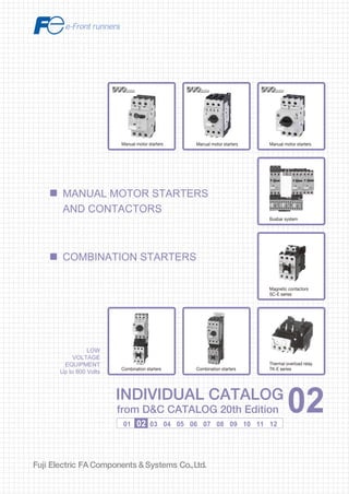
  • 1. Information in this catalog is subject to change without notice. 5-7, Nihonbashi Odemma-cho, Chuo-ku, Tokyo, 103-0011, Japan URL http://www.fujielectric.co.jp/fcs/eng INDIVIDUALCATALOGfromD&CCATALOG20thEdition 02 LOW VOLTAGE PRODUCTS Up to 600 Volts Individual catalog No. 01 Magnetic Contactors and Starters Thermal Overload Relays, Solid-state Contactors 02 Industrial Relays, Industrial Control Relays Annunciator Relay Unit, Time Delay Relays Manual Motor Starters and Contactors Combination Starters Pushbuttons, Selector Switches, Pilot Lights Rotary Switches, Cam Type Selector Switches Panel Switches, Terminal Blocks, Testing Terminals Molded Case Circuit Breakers Air Circuit Breakers Earth Leakage Circuit Breakers Earth Leakage Protective Relays Measuring Instruments, Arresters, Transducers Power Factor Controllers Power Monitoring Equipment (F-MPC) Circuit Protectors Low Voltage Current-Limiting Fuses 03 04 05 06 07 08 09 10 HIGH VOLTAGE PRODUCTS Up to 36kV 11 Disconnecting Switches, Power Fuses Air Load Break Switches Instrument Transformers — VT, CT D&C CATALOG DIGEST INDEX AC Power Regulators Noise Suppression Filters Control Power Transformers 12 Vacuum Circuit Breakers, Vacuum Magnetic Contactors Protective Relays Limit Switches, Proximity Switches Photoelectric Switches 01 02 03 04 05 06 07 08 09 10 11 12 LOW VOLTAGE EQUIPMENT Up to 600 Volts INDIVIDUAL CATALOG from D&C CATALOG 20th Edition 02INDIVIDUAL CATALOG from D&C CATALOG 20th Edition 02 COMBINATION STARTERS MANUAL MOTOR STARTERS AND CONTACTORS Manual motor starters Manual motor starters Busbar system Magnetic contactors SC-E series Thermal overload relay TK-E seriesCombination starters Manual motor starters Combination starters 2010-09 PDF FOLS DEC2002
  • 2. Tư vấn chọn sản phẩm Giao hàng tận nơi Hỗ trợ kỹ thuật Chính sách hậu mãi đa dạng DỊCH VỤ CHĂM SÓC KHÁCH HÀNG TOÀN DIỆN Nhà cung cấp thiết bị điện chuyên nghiệp Hotline: 0904.676.925 CÔNG TY TNHH THƯƠNG MẠI KỸ THUẬT ASTER Số 7 Đại lộ Độc Lập, KCN Sóng Thần, P. Dĩ An, Tx. Dĩ An, Bình Dương, VN. Tel: (0650) 3617 012 Fax: (0650) 3617 011 www.beeteco.com
  • 3. General information .............................................................................................. 02/1 Manual motor starters General information .......................................................................................... 02/2 Quick reference guide ...................................................................................... 02/5 Adjustable thermal-magnetic trip types ............................................................ 02/8 Instantaneous trip types ................................................................................... 02/10 Ring terminal connection types ........................................................................ 02/11 UL listed ............................................................................................................ 02/13 Characteristic curves ........................................................................................ 02/14 Optional accessories ........................................................................................ 02/15 Dimensions ....................................................................................................... 02/21 Wiring diagrams ................................................................................................ 02/24 Operating conditions ......................................................................................... 02/25 Busbar system .................................................................................................. 02/26 Enclosures ........................................................................................................ 02/30 SC-M and SC-E series General information .......................................................................................... 02/32 SC-M series contactors .................................................................................... 02/35 Optional accessories .................................................................................... 02/39 Dimensions ................................................................................................... 02/40 SC-E series contactors ..................................................................................... 02/43 Optional accessories .................................................................................... 02/51 Dimensions ................................................................................................... 02/53 Operating conditions .................................................................................... 02/63 Thermal overload relays TK-E series ........................................................... 02/65 Features................................................................................................................ 02/71 Protective coordination ......................................................................................... 02/72 Combinations meeting for UL market ................................................................... 02/76 Optional accessories ............................................................................................ 02/77 Dimensions ........................................................................................................... 02/80 CCC approved ...................................................................................................... 02/85 02 DUO Series Combination Starters DUO Series Contactors DUO series Manual Motor Starters and Contactors Combination Starters DUO Series MMS and Contactors Page DUO Series MMS and Contactors
  • 4. MINIMUM ORDERS Orders amounting to less than ¥10,000 net per order will be charged as ¥10,000 net per order plus freight and other charges. WEIGHTS AND DIMENSIONS Weights and dimensions appearing in this catalog are the best information available at the time of going to press. FUJI ELECTRIC FA has a policy of continuous product improvement, and design changes may make this information out of date. Please confirm such details before planning actual construction. INFORMATION IN THIS CATALOG IS SUBJECT TO CHANGE WITHOUT NOTICE.
  • 5. Fuji Electric FA Components & Systems Co., Ltd./D & C Catalog Information subject to change without notice 02/1 02 DUO series MMS and Contactors General information s Description FUJI offers a new motor control system – DUO series for the international market, designed to IEC standards. The DUO series adds a new family of compact, high-performance combination starters to its IEC-compliant manual motor starters BM3 series, magnetic contactors SC series and thermal overload relays TK series to form a complete line-up of motor control products. • Short-circuit protective coordination between protective devices and the equipment to be protected • Conformance to IEC, UL, CSA and other international standards • Safety and ecological consideration – safety features such as terminals with finger protection, use of recyclable materials, and resources-saving Manual motor starters (MMS) BM3 series New circuit breakers for motor use that provide optimal protection by integrating the functions of a molded case circuit breaker and thermal overload relay into a highly compact unit. See page 02/2 Contactors and thermal overload relays SC-M and SC-E series SC-M series compact magnetic contactors for small capacity motor control for 400V AC, 2.2 to 4kW. SC-E series magnetic contactors and thermal overload relays featuring terminals with finger protection for 400V AC, 4 to 75kW. See page 02/32 Combination starters The ability to configure combination starters for compact, reliable motor protection by combining a manual motor starter and a magnetic contactor. See page 02/74 BM3 series SC-E series BM3RSB-010 + SC-M02 SC-M series KK02-162 KK02-152 BM3VHB-050 + SC-E2S Manual motor starters (MMS) Contactors and thermal overload relays
  • 6. DUO series Manual Motor Starters 02/2 Fuji Electric FA Components & Systems Co., Ltd./D & C Catalog Information subject to change without notice General information BM3VSB and BM3VSBK Rated current: 10 to 63A Rated insulation voltage: 1000V Operation handle: Rotary handle Breaking capacity Icu at 400/415V: • 100kA up to 10A • 50kA up to 13A • 25kA up to 63A BM3VHB and BM3VHBK Rated current: 10 to 63A Rated insulation voltage: 1000V Operation handle: Rotary handle Breaking capacity Icu at 400/415V: • 100kA up to 13A • 50kA up to 63A BM3RHB and BM3RHBK Rated current: 0.16 to 32A Rated insulation voltage: 690V Operation handle: Rotary handle Breaking capacity Icu at 400/415V: • 100kA up to 13A • 50kA up to 32A BM3RSB and BM3RSBK Rated current: 0.16 to 32A Rated insulation voltage: 690V Operation handle: Rocker handle Breaking capacity Icu at 400/415V: • 100kA up to 10A • 50kA up to 13A • 25kA up to 32AKK01-317 AF01-42 AF01-47 AF01-43 Manual motor starters BM3 series s Description Conforming to international standards and combining compactness with high breaking performance, this versatile series features leading-edge motor protection. Molded case circuit breaker and thermal overload relay functions are integrated into a highly compact unit. s Features • Eight types available in two different frame sizes-32AF for the 45mm width and 63AF for the 55mm width • A wide motor capacity range up to 30kW (400/415V AC, 63A) • High breaking capacity Standard breaking capacity: 25, 50, 100kA 400V AC High breaking capacity: 50, 100kA 400V AC • Adjustable thermal-magnetic trip types 32AF: BM3RSB and BM3RHB 63AF: BM3VSB and BM3VHB • Instantaneous trip types 32AF: BM3RSBK and BM3RHBK 63AF: BM3VSBK and BM3VHBK • Common accessories to reduce inventory • Short-circuit protective coordination IEC 60947-4-1 Type1, 2 • Standards IEC 60947-1, 60947-2, 60947-4-1, UL 508, CSA C22.2 No.14 • Ecological design Recyclable thermoplastic resin used in plastic parts Indication of materials used Cadmium-free contacts • Both rocker and rotary handle • ON/OFF and trip state indication for all frames Circuit breaker functions • Short-circuit protection • Overcurrent protection • Line protection Thermal overload relay functions • Overload protection • Phase-loss protection • Rated current adjustment • Ambient temperature compensation Compactness: 57% reduction Wiring work: 50% reduction Manual motor starters BM3 series
  • 7. DUO series Manual Motor Starters Fuji Electric FA Components & Systems Co., Ltd./D & C Catalog Information subject to change without notice 02/3 02 General information s Manual motor starters for branch circuit protection The MMS provides reliable protection for overloading and short-circuiting in motor branch circuits. Typical problem in the conventional system Solution by using MMS system Short-circuit breaking protection When numerous small and medium motor loads exist in a circuit requiring high breaking capacity, there is no high-breaking capacity circuit breaker with a small rated current for short-circuit protection. Back-up breaking system When a back-up MCCB is installed upstream to slove the probrem described in "short-circuit breaking protection" above, an occurrence of short-circuit failure in a single load circuit also trips the upstream breaker and stops the other operating load circuits. Overload protection Motor protection breakers cannot be adjusted to match the rated current of the motor being protected. Control panel size Considerable space is required to install a back-up circuit breaker or a combination starter consisting of a circuit breaker and a thermal overload relay. As a result, the panel size has to be increased. The MMS can be used in 100kA short-circuit current circuits for three-phase, 240V motors with rated capacity up to 15kW, and in 50kA short-circuit current circuits for three-phase, 415V motors with rated capacity up to 30kW. Despite their compact size, the 32AF and 63AF MMS provide high-performance short-circuit current breaking. They eliminate the need for an upstream circuit breaker for back-up use. Equipped with a wide-range current adjustment dial (with maximum/minimum ratio of 1.4 to 1.6), the MMS easily adjusts to match the rated current of the motor, for optimum protection. The compact size of the MMS, including thermal overload relay functions, enables a smaller installation area with less wiring space, for a reduction in panel size. MCCB Motor 2Motor 1 Contactor + MCCB MCCB Contactor + Motor 1 Motor 2 Thermal overload relay Thermal overload relay MCCB Contactors Manual motor starters Motors
  • 8. DUO series Manual Motor Starters 02/4 Fuji Electric FA Components & Systems Co., Ltd./D & C Catalog Information subject to change without notice General information s Accessories A wide variety of accessories enables a flexible response to changes in specifications. Snap-on fittings speed up mounting. 9mm external device Left-side mounting Internal device Front mounting MMS 9mm external device Right-side mounting 18mm external device Right-side mounting Aux. contact block Alarm contact block 45mm Auxiliary contact blocks Undervoltage trip device with early make contacts Undervoltage trip device with early make contacts Undervoltage trip device Shunt trip device 55mm Emergency-stop handle Standard operation handle Enclosures Short-circuit alarm contact block Short-circuit alarm contact block Auxiliary/alarm contact blocks Auxiliary contact blocks
  • 9. DUO series Manual Motor Starters Fuji Electric FA Components & Systems Co., Ltd./D & C Catalog Information subject to change without notice 02/5 02 Quick reference guide s 32AF types and ratings Note: * 1 Adjustable thermal-magnetic trip type only Available – Not available * 2 When the breaking duty is once “0” in JEM 1195, the breaking capacity is 50kA. Replace the mark in the type number by current range codes. Standard breaking capacity High breaking capacity Adjustable thermal-magnetic trip type BM3RSB- BM3RHB- Instantaneous trip type BM3RHBK- KK01-317 AF01-42 Number of poles 3 3 Handle type Rocker Rotary Rated current In (A) 0.16 to 32 Rated operational voltage Ue (V) 200 to 690 Rated frequency (Hz) 50/60 Rated insulation voltage Ui (V) 690 Rated impulse withstand voltage Uimp (kV) 6 Utilization IEC 60947-2 Circuit breaker Cat. A category IEC 60947-4-1 Motor starter AC-3 Trip class IEC 60947-4-1 *1 10 Instantaneous trip characteristic 13 ln max. Power loss (total of 3-pole) 7W: In=0.16 to 25A 8.5W: In=32A Mechanical durability (operations) 100,000: In=0.16 to 25A 70,000: In=32A Electrical durability (operations) 100,000: In=0.16 to 25A 70,000: In=32A Max. operations per hour (motor start-up) 25 Phase-loss protection Provided Tripping state indication Provided Test trip function Provided Rated breaking Adjustable current range 240V 415V 460V 500V 690V 240V 415V 460V 500V 690V capacity (kA) Code Ie: Min.–Max. 230V 400V 440V 600V 230V 400V 440V 600V IEC 60947-2 (A) Icu Ics Icu Ics Icu Ics Icu Ics Icu Ics Icu Ics Icu Ics Icu Ics Icu Ics Icu Ics P16 0.1–0.16 100 100 100 100 100 100 100 100 100 100 100 100 100 100 100 100 100 100 100 100 P25 0.16–0.25 100 100 100 100 100 100 100 100 100 100 100 100 100 100 100 100 100 100 100 100 P40 0.25–0.4 100 100 100 100 100 100 100 100 100 100 100 100 100 100 100 100 100 100 100 100 P63 0.4–0.63 100 100 100 100 100 100 100 100 100 100 100 100 100 100 100 100 100 100 100 100 001 0.63–1. 100 100 100 100 100 100 100 100 100 100 100 100 100 100 100 100 100 100 100 100 1P6 1–1.6 100 100 100 100 100 100 100 100 100 100 100 100 100 100 100 100 100 100 100 100 2P5 1.6–2.5 100 100 100 100 100 100 100 100 3 2 100 100 100 100 100 100 100 100 8 6 004 2.5–4. 100 100 100 100 100 100 100 100 3 2 100 100 100 100 100 100 100 100 8 6 6P3 4–6.3 100 100 100 100 50 38 50 38 3 2 100 100 100 100 100 100 100 100 6 5 010 6.3–10 . 100 100 100 100 15 11 10 8 3 2 100 100 100 100 50 38 50 38 6 5 013 9–13 . 100 100 50 38 10 8 6 5 3 2 100 100 100 100 50 38 42 32 6 5 016 11–16 . 100 100 25 19 10 8 6 5 3 2 100 100 50 38 35*2 27 10 8 4 3 020 14–20 . 50 38 25 19 10 8 6 5 3 2 100 100 50 38 35*2 27 10 8 4 3 025 19–25 . 50 38 25 19 10 8 6 5 3 2 100 100 50 38 35*2 27 10 8 4 3 032 24–32 . 50 38 25 19 10 8 6 5 3 2 100 100 50 38 35*2 27 10 8 4 3 040 28–40 . – – – – – – – – – – 050 35–50 . – – – – – – – – – – 063 45–63 . – – – – – – – – – – Dimensions (mm) W H D 45 90 66 45 90 79 Mass (g) 350 370 Optional Auxiliary contact block accessory Alarm contact block Auxiliary and alarm contact block Short-circuit alarm contact block Shunt trip device Undervoltage trip device External operating handle – Standard IEC 60947-1, 60947-2, 60947-4-1, UL 508, CSA C22.2 No.14, TÜV
  • 10. DUO series Manual Motor Starters 02/6 Fuji Electric FA Components & Systems Co., Ltd./D & C Catalog Information subject to change without notice Quick reference guide s 63AF types and ratings Replace the mark in the type number by current range codes. Note: * 1 Adjustable thermal-magnetic trip type only Available – Not available * 2 When the breaking duty is once “0” in JEM 1195, the breaking capacity is 50kA. Standard breaking capacity High breaking capacity Adjustable thermal-magnetic trip type BM3VSB- BM3VHB- Instantaneous trip type BM3VHBK- AF01-47 AF01-43 Number of poles 3 3 Handle type Rotary Rotary Rated current In (A) 10 to 63 Rated operational voltage Ue (V) 200 to 690 Rated frequency (Hz) 50/60 Rated insulation voltage Ui (V) 1000 Rated impulse withstand voltage Uimp (kV) 8 Utilization IEC 60947-2 Circuit breaker Cat. A category IEC 60947-4-1 Motor starter AC-3 Trip class IEC 60947-4-1 *1 10 Instantaneous trip characteristic 13 ln max. Power loss (total of 3-pole ) 11W: In=10 to 32A 15W: In=40 to 50A 17W: In=63A Mechanical durability (operations) 50,000 Electrical durability (operations) 25,000 Max. operations per hour (motor start-up) 25 Phase-loss protection Provided Tripping state indication Provided Test trip function Provided Rated breaking Adjustable current range 240V 415V 460V 500V 690V 240V 415V 460V 500V 690V capacity (kA) Code Ie: Min.–Max. 230V 400V 440V 600V 230V 400V 440V 600V IEC 60947-2 (A) Icu Ics Icu Ics Icu Ics Icu Ics Icu Ics Icu Ics Icu Ics Icu Ics Icu Ics Icu Ics P16 0.1–0.16 – – – – – – – – – – P25 0.16–0.25 – – – – – – – – – – P40 0.25–0.4 – – – – – – – – – – P63 0.4–0.63 – – – – – – – – – – 001 0.63–1. – – – – – – – – – – 1P6 1–1.6 – – – – – – – – – – 2P5 1.6–2.5 – – – – – – – – – – 004 2.5–4. – – – – – – – – – – 6P3 4–6.3 – – – – – – – – – – 010 6.3–10 . 100 100 100 100 15 12 10 8 4 3 100 100 100 100 50 38 50 38 6 5 013 9–13 . 100 100 50 38 10 8 6 5 4 3 100 100 100 100 50 38 42 32 6 5 016 11–16 . 100 100 25 19 10 8 6 5 4 3 100 100 50 38 50 38 12 9 5 4 020 14–20 . 50 38 25 19 10 8 6 5 4 3 100 100 50 38 50 38 12 9 5 4 025 19–25 . 50 38 25 19 10 8 6 5 4 3 100 100 50 38 35*2 27 12 9 5 4 032 24–32 . 50 38 25 19 10 8 6 5 4 3 100 100 50 38 35*2 27 10 8 5 4 040 28–40 . 50 38 25 19 10 8 6 5 4 3 100 100 50 38 35*2 27 10 8 5 4 050 35–50 . 50 38 25 19 10 8 6 5 4 3 100 100 50 38 35*2 27 10 8 5 4 063 45–63 . 50 38 25 19 10 8 6 5 4 3 100 100 50 38 35*2 27 10 8 5 4 Dimensions (mm) W H D 55 110 96 Mass (g) 780 Optional Auxiliary contact block accessory Alarm contact block Auxiliary and alarm contact block Short-circuit alarm contact block Shunt trip device Undervoltage trip device External operating handle Standard IEC 60947-1, 60947-2, 60947-4-1, UL 508, CSA C22.2 No.14, TÜV
  • 11. DUO series Manual Motor Starters Fuji Electric FA Components & Systems Co., Ltd./D & C Catalog Information subject to change without notice 02/7 02 Quick reference guide s 32AF types and ratings, with ring terminal connection Note: * 1 Adjustable thermal-magnetic trip type only Available – Not available * 2 When the breaking duty is once “0” in JEM 1195, the breaking capacity is 50kA. Replace the mark in the type number by current range codes. Standard breaking capacity High breaking capacity Adjustable thermal-magnetic trip type BM3RSR- BM3RHR- Instantaneous trip type BM3RHRK- KKD05-197 KKD05-198 Number of poles 3 3 Handle type Rocker Rotary Rated current In (A) 0.16 to 32 Rated operational voltage Ue (V) 200 to 690 Rated frequency (Hz) 50/60 Rated insulation voltage Ui (V) 690 Rated impulse withstand voltage Uimp (kV) 6 Utilization IEC 60947-2 Circuit breaker Cat. A category IEC 60947-4-1 Motor starter AC-3 Trip class IEC 60947-4-1 *1 10 Instantaneous trip characteristic 13 ln max. Power loss (total of 3-pole) 7W: In=0.16 to 25A 8.5W: In=32A Mechanical durability (operations) 100,000: In=0.16 to 25A 70,000: In=32A Electrical durability (operations) 100,000: In=0.16 to 25A 70,000: In=32A Max. operations per hour (motor start-up) 25 Phase-loss protection Provided Tripping state indication Provided Test trip function Provided Rated breaking Adjustable current range 240V 415V 460V 500V 690V 240V 415V 460V 500V 690V capacity (kA) Code Ie: Min.–Max. 230V 400V 440V 600V 230V 400V 440V 600V IEC 60947-2 (A) Icu Ics Icu Ics Icu Ics Icu Ics Icu Ics Icu Ics Icu Ics Icu Ics Icu Ics Icu Ics P16 0.1–0.16 100 100 100 100 100 100 100 100 100 100 100 100 100 100 100 100 100 100 100 100 P25 0.16–0.25 100 100 100 100 100 100 100 100 100 100 100 100 100 100 100 100 100 100 100 100 P40 0.25–0.4 100 100 100 100 100 100 100 100 100 100 100 100 100 100 100 100 100 100 100 100 P63 0.4–0.63 100 100 100 100 100 100 100 100 100 100 100 100 100 100 100 100 100 100 100 100 001 0.63–1. 100 100 100 100 100 100 100 100 100 100 100 100 100 100 100 100 100 100 100 100 1P6 1–1.6 100 100 100 100 100 100 100 100 100 100 100 100 100 100 100 100 100 100 100 100 2P5 1.6–2.5 100 100 100 100 100 100 100 100 3 2 100 100 100 100 100 100 100 100 8 6 004 2.5–4. 100 100 100 100 100 100 100 100 3 2 100 100 100 100 100 100 100 100 8 6 6P3 4–6.3 100 100 100 100 50 38 50 38 3 2 100 100 100 100 100 100 100 100 6 5 010 6.3–10 . 100 100 100 100 15 11 10 8 3 2 100 100 100 100 50 38 50 38 6 5 013 9–13 . 100 100 50 38 10 8 6 5 3 2 100 100 100 100 50 38 42 32 6 5 016 11–16 . 100 100 25 19 10 8 6 5 3 2 100 100 50 38 35*2 27 10 8 4 3 020 14–20 . 50 38 25 19 10 8 6 5 3 2 100 100 50 38 35*2 27 10 8 4 3 025 19–25 . 50 38 25 19 10 8 6 5 3 2 100 100 50 38 35*2 27 10 8 4 3 032 24–32 . 50 38 25 19 10 8 6 5 3 2 100 100 50 38 35*2 27 10 8 4 3 040 28–40 . – – – – – – – – – – 050 35–50 . – – – – – – – – – – 063 45–63 . – – – – – – – – – – Dimensions (mm) W H D 45 90 66 45 90 79 Mass (g) 350 370 Optional Auxiliary contact block accessory Alarm contact block Auxiliary and alarm contact block Short-circuit alarm contact block Shunt trip device Undervoltage trip device External operating handle – Standard IEC 60947-1, 60947-2, 60947-4-1, UL 508, CSA C22.2 No.14, TÜV
  • 12. DUO series Manual Motor Starters 02/8 Fuji Electric FA Components & Systems Co., Ltd./D & C Catalog Information subject to change without notice Adjustable thermal-magnetic trip types Max. motor capacity and full-load current Rated Thermal Instantaneous Rated breaking Type 3-phase *1 current *2 current trip current capacity Icu (kA) 200-240V AC 380-440V AC In (A) setting range (A) (kW) (A) (kW) (A) Ie (A) 240V AC 415V AC 440V AC – – 0.02 0.1 0.16 0.1–0.16 2.1 100 100 100 BM3RSB-P16 0.03 0.24 0.06 0.21 0.25 0.16–0.25 3.3 100 100 100 BM3RSB-P25 0.06 0.37 0.1 0.34 0.4 0.25–0.4 5.2 100 100 100 BM3RSB-P40 0.06 0.37 0.12 0.41 0.63 0.4–0.63 8.2 100 100 100 BM3RSB-P63 0.1 0.68 0.2 0.65 1 0.63–1. 13 100 100 100 BM3RSB-001 0.2 1.3 0.4 1.15 1.6 1–1.6 20.8 100 100 100 BM3RSB-1P6 0.4 2.3 0.75 1.8 2.5 1.6–2.5 32.5 100 100 100 BM3RSB-2P5 0.75 3.6 1.5 3.1 4 2.5–4. 52 100 100 100 BM3RSB-004 1.5 6.1 2.2 4.6 6.3 4–6.3 81.9 100 100 50 BM3RSB-6P3 2.2 9.2 3.7 7.5 10 6.3–10 . 130 100 100 15 BM3RSB-010 2.2 9.2 5.5 11.5 13 9–13 . 169 100 50 10 BM3RSB-013 3.7 15 7.5 14.5 16 11–16 . 208 100 25 10 BM3RSB-016 3.7 15 7.5 14.5 20 14–20 . 260 50 25 10 BM3RSB-020 5.5 22.5 11 21 25 19–25 . 325 50 25 10 BM3RSB-025 7.5 29 15 27.5 32 24–32 . 416 50 25 10 BM3RSB-032 s Types and ratings • 32AF standard breaking capacity, rocker handle types Adjustable thermal-magnetic trip types s Features • A wide rated operational current range of up to 32A for the 45mm wide and 63A for the 55mm wide starters. • ON/OFF and trip indications ensure instant status recognition. • Suitable for 3-phase motors up to 30kW at 440V AC, AC-3. • Accessories like auxiliary contact blocks, shunt trip devices, and undervoltage trip devices have been standardized for the 45mm and 55mm wide frame sizes of the BM3R and BM3V. • Enclosures and external operating handles are available as optional accessories. s Standards IEC 60947-1, 60947-2, 60947-4-1, UL 508, CSA C22.2 No.14, TÜV, CCC Notes: *1 Motor full-load currents are based on FUJI’s standard type totally-enclosed induction motors. *2 Max. thermal current setting value BM3VHB AF01-43 BM3RHB AF01-42 BM3RSB KK01-317 • 32AF high breaking capacity, rotary handle types Max. motor capacity and full-load current Rated Thermal Instantaneous Rated breaking Type 3-phase *1 current *2 current trip current capacity Icu (kA) 200-240V AC 380-440V AC In (A) setting range (A) (kW) (A) (kW) (A) Ie (A) 240V AC 415V AC 440V AC – – 0.02 0.1 0.16 0.1–0.16 2.1 100 100 100 BM3RHB-P16 0.03 0.24 0.06 0.21 0.25 0.16–0.25 3.3 100 100 100 BM3RHB-P25 0.06 0.37 0.1 0.34 0.4 0.25–0.4 5.2 100 100 100 BM3RHB-P40 0.06 0.37 0.12 0.41 0.63 0.4–0.63 8.2 100 100 100 BM3RHB-P63 0.1 0.68 0.2 0.65 1 0.63–1. 13 100 100 100 BM3RHB-001 0.2 1.3 0.4 1.15 1.6 1–1.6 20.8 100 100 100 BM3RHB-1P6 0.4 2.3 0.75 1.8 2.5 1.6–2.5 32.5 100 100 100 BM3RHB-2P5 0.75 3.6 1.5 3.1 4 2.5–4. 52 100 100 100 BM3RHB-004 1.5 6.1 2.2 4.6 6.3 4–6.3 81.9 100 100 100 BM3RHB-6P3 2.2 9.2 3.7 7.5 10 6.3–10 . 130 100 100 50 BM3RHB-010 2.2 9.2 5.5 11.5 13 9–13 . 169 100 100 50 BM3RHB-013 3.7 15 7.5 14.5 16 11–16 . 208 100 50 35 BM3RHB-016 3.7 15 7.5 14.5 20 14–20 . 260 100 50 35 BM3RHB-020 5.5 22.5 11 21 25 19–25 . 325 100 50 35 BM3RHB-025 7.5 29 15 27.5 32 24–32 . 416 100 50 35 BM3RHB-032
  • 13. DUO series Manual Motor Starters Fuji Electric FA Components & Systems Co., Ltd./D & C Catalog Information subject to change without notice 02/9 02 Adjustable thermal-magnetic trip types • 63AF standard breaking capacity, rotary handle types • 63AF high breaking capacity, rotary handle types Notes: *1 Motor full-load currents are based on FUJI’s standard type totally-enclosed induction motors. *2 Max. thermal current setting value BM3VHB - 063 (CCC) Basic type Frame size Rated current Operating characteristic R: 32AF 45mm wide V: 63AF 55mm wide B: Adjustable thermal-magnetic trip BK: Instantaneous trip R: Adjustable thermal-magnetic trip, ring terminal RK: Instantaneous trip, ring terminal Breaking capacity S: Standard breaking capacity H: High breaking capacity s Ordering information Specify the following: 1. Type number 2. Accessories if required s Type number nomenclature CCC approved Max. motor capacity and full-load current Rated Thermal Instantaneous Rated breaking Type 3-phase *1 current *2 current trip current capacity Icu (kA) 200-240V AC 380-440V AC In (A) setting range (A) (kW) (A) (kW) (A) Ie (A) 240V AC 415V AC 440V AC 2.2 9.2 3.7 7.5 10 6.3–10 130 100 100 15 BM3VSB-010 2.2 9.2 5.5 11.5 13 9–13 169 100 50 10 BM3VSB-013 3.7 15 7.5 14.5 16 11–16 208 100 25 10 BM3VSB-016 3.7 15 7.5 14.5 20 14–20 260 50 25 10 BM3VSB-020 5.5 22.5 11 21 25 19–25 325 50 25 10 BM3VSB-025 7.5 29 15 27.5 32 24–32 416 50 25 10 BM3VSB-032 7.5 29 18.5 34 40 28–40 520 50 25 10 BM3VSB-040 11 42 22 39 50 35–50 650 50 25 10 BM3VSB-050 15 55 30 54 63 45–63 819 50 25 10 BM3VSB-063 Max. motor capacity and full-load current Rated Thermal Instantaneous Rated breaking Type 3-phase *1 current *2 current trip current capacity Icu (kA) 200-240V AC 380-440V AC In (A) setting range (A) (kW) (A) (kW) (A) Ie (A) 240V AC 415V AC 440V AC 2.2 9.2 3.7 7.5 10 6.3–10 130 100 100 50 BM3VHB-010 2.2 9.2 5.5 11.5 13 9–13 169 100 100 50 BM3VHB-013 3.7 15 7.5 14.5 16 11–16 208 100 50 50 BM3VHB-016 3.7 15 7.5 14.5 20 14–20 260 100 50 50 BM3VHB-020 5.5 22.5 11 21 25 19–25 325 100 50 35 BM3VHB-025 7.5 29 15 27.5 32 24–32 416 100 50 35 BM3VHB-032 7.5 29 18.5 34 40 28–40 520 100 50 35 BM3VHB-040 11 42 22 39 50 35–50 650 100 50 35 BM3VHB-050 15 55 30 54 63 45–63 819 100 50 35 BM3VHB-063
  • 14. DUO series Manual Motor Starters 02/10 Fuji Electric FA Components & Systems Co., Ltd./D & C Catalog Information subject to change without notice Instantaneous trip types Max. motor capacity and full-load current Rated current Instantaneous trip Rated breaking Type 3-phase * In (A) current (A) capacity Icu (kA) 200-240V AC 380-440V AC (kW) (A) (kW) (A) 240V AC 415V AC 440V AC 2.2 9.2 3.7 7.5 10 130 100 100 50 BM3VHBK-010 2.2 9.2 5.5 11.5 13 169 100 100 50 BM3VHBK-013 3.7 15 7.5 14.5 16 208 100 50 50 BM3VHBK-016 3.7 15 7.5 14.5 20 260 100 50 50 BM3VHBK-020 5.5 22.5 11 21 25 325 100 50 35 BM3VHBK-025 7.5 29 15 27.5 32 416 100 50 35 BM3VHBK-032 7.5 29 18.5 34 40 520 100 50 35 BM3VHBK-040 11 42 22 39 50 650 100 50 35 BM3VHBK-050 15 55 30 54 63 819 100 50 35 BM3VHBK-063 Notes: *1 Motor full-load currents are based on FUJI’s standard type totally-enclosed induction motors. • Select appropriate thermal overload relay for starter. Instantaneous trip types s Features • Instantaneous trip type for short-circuit or overcurrent protection of three-phase motors up to 63A (240V AC, 15kW, or 440V AC, 30kW). • A motor overload protection function is not provided. Protecting the motor circuits is possible by using the starter together with a thermal overload relay that is matched to the thermal characteristics and startup time of the motor. • Two modules, 45mm or 55mm wide, cover current ratings from 0.1 to 63A. RHBK: 45mm wide, rated current of 0.1 to 32A VHBK: 55mm wide, rated current of 6.3 to 63A • Rotary handle • Versatile accessories Internal and external auxiliary contact blocks, alarm contact block Short-circuit alarm contact block Shunt trip device Undervoltage trip device BM3VHBKBM3RHBK • 63AF high breaking capacity, rotary handle type s Standards IEC 60947-1, 60947-2, 60947-4-1, UL 508 CSA C22.2 No.14, TÜV, CCC s Types and ratings • 32AF high breaking capacity, rotary handle type AF01-46 AF01-45 Max. motor capacity and full-load current Rated current Instantaneous trip Rated breaking Type 3-phase * In (A) current (A) capacity Icu (kA) 200-240V AC 380-440V AC (kW) (A) (kW) (A) 240V AC 415V AC 440V AC – – 0.02 0.1 0.16 2.1 100 100 100 BM3RHBK-P16 0.03 0.24 0.06 0.21 0.25 3.3 100 100 100 BM3RHBK-P25 0.06 0.37 0.1 0.34 0.4 5.2 100 100 100 BM3RHBK-P40 0.06 0.37 0.12 0.41 0.63 8.2 100 100 100 BM3RHBK-P63 0.1 0.68 0.2 0.65 1 13 100 100 100 BM3RHBK-001 0.2 1.3 0.4 1.15 1.6 20.8 100 100 100 BM3RHBK-1P6 0.4 2.3 0.75 1.8 2.5 32.5 100 100 100 BM3RHBK-2P5 0.75 3.6 1.5 3.1 4 52 100 100 100 BM3RHBK-004 1.5 6.1 2.2 4.6 6.3 81.9 100 100 100 BM3RHBK-6P3 2.2 9.2 3.7 7.5 10 130 100 100 50 BM3RHBK-010 2.2 9.2 5.5 11.5 13 169 100 100 50 BM3RHBK-013 3.7 15 7.5 14.5 16 208 100 50 35 BM3RHBK-016 3.7 15 7.5 14.5 20 260 100 50 35 BM3RHBK-020 5.5 22.5 11 21 25 325 100 50 35 BM3RHBK-025 7.5 29 15 27.5 32 416 100 50 35 BM3RHBK-032 Notes: * Motor full-load currents are based on FUJI’s standard type totally-enclosed induction motors. • Select appropriate thermal overload relay for starter.
  • 15. DUO series Manual Motor Starters Fuji Electric FA Components & Systems Co., Ltd./D & C Catalog Information subject to change without notice 02/11 02 Ring terminal connection types Adjustable thermal-magnetic trip types Max. motor capacity and full-load current Rated Thermal Instantaneous Rated breaking Type 3-phase *1 current *2 current trip current capacity Icu (kA) 200-240V AC 380-440V AC In (A) setting range (A) (kW) (A) (kW) (A) Ie (A) 240V AC 415V AC 440V AC – – 0.02 0.1 0.16 0.1–0.16 2.1 100 100 100 BM3RSR-P16 0.03 0.24 0.06 0.21 0.25 0.16–0.25 3.3 100 100 100 BM3RSR-P25 0.06 0.37 0.1 0.34 0.4 0.25–0.4 5.2 100 100 100 BM3RSR-P40 0.06 0.37 0.12 0.41 0.63 0.4–0.63 8.2 100 100 100 BM3RSR-P63 0.1 0.68 0.2 0.65 1 0.63–1. 13 100 100 100 BM3RSR-001 0.2 1.3 0.4 1.15 1.6 1–1.6 20.8 100 100 100 BM3RSR-1P6 0.4 2.3 0.75 1.8 2.5 1.6–2.5 32.5 100 100 100 BM3RSR-2P5 0.75 3.6 1.5 3.1 4 2.5–4. 52 100 100 100 BM3RSR-004 1.5 6.1 2.2 4.6 6.3 4–6.3 81.9 100 100 50 BM3RSR-6P3 2.2 9.2 3.7 7.5 10 6.3–10 . 130 100 100 15 BM3RSR-010 2.2 9.2 5.5 11.5 13 9–13 . 169 100 50 10 BM3RSR-013 3.7 15 7.5 14.5 16 11–16 . 208 100 25 10 BM3RSR-016 3.7 15 7.5 15 20 14–20 . 260 50 25 10 BM3RSR-020 5.5 22.5 11 21 25 19–25 . 325 50 25 10 BM3RSR-025 7.5 29 15 27.5 32 24–32 . 416 50 25 10 BM3RSR-032 s Types and ratings • 32AF standard breaking capacity, rocker handle types Ring terminal connection types Adjustable thermal-magnetic trip types s Features • Similar to FUJI MCCBs, the new type allows easy mounting and removal of the terminal cover, and up to two ring crimp terminals can be connected from the upper terminal part. • Straight wiring connection is also possible in addition to ring terminal connection. • The BM3RSR (0.16 to 32A rocker handle types) and BM3RHR (0.16 to 32A rotary handle types) are available. • All optional accessories for standard manual motor starters can be mounted. • The series conforms to IEC, UL and JIS standards, as do the standard manual motor starters. • Crimp terminal insulation and a long terminal cover conforming to UL508 type E and F standards are available. (Purchased separately.) Notes: *1 Motor full-load currents are based on FUJI’s standard type totally-enclosed induction motors. *2 Max. thermal current setting value BM3RSR KK04-055 • 32AF high breaking capacity, rotary handle types Max. motor capacity and full-load current Rated Thermal Instantaneous Rated breaking Type 3-phase *1 current *2 current trip current capacity Icu (kA) 200-240V AC 380-440V AC In (A) setting range (A) (kW) (A) (kW) (A) Ie (A) 240V AC 415V AC 440V AC – – 0.02 0.1 0.16 0.1–0.16 2.1 100 100 100 BM3RHR-P16 0.03 0.24 0.06 0.21 0.25 0.16–0.25 3.3 100 100 100 BM3RHR-P25 0.06 0.37 0.1 0.34 0.4 0.25–0.4 5.2 100 100 100 BM3RHR-P40 0.06 0.37 0.12 0.41 0.63 0.4–0.63 8.2 100 100 100 BM3RHR-P63 0.1 0.68 0.2 0.65 1 0.63–1. 13 100 100 100 BM3RHR-001 0.2 1.3 0.4 1.15 1.6 1–1.6 20.8 100 100 100 BM3RHR-1P6 0.4 2.3 0.75 1.8 2.5 1.6–2.5 32.5 100 100 100 BM3RHR-2P5 0.75 3.6 1.5 3.1 4 2.5–4. 52 100 100 100 BM3RHR-004 1.5 6.1 2.2 4.6 6.3 4–6.3 81.9 100 100 100 BM3RHR-6P3 2.2 9.2 3.7 7.5 10 6.3–10 . 130 100 100 50 BM3RHR-010 2.2 9.2 5.5 11.5 13 9–13 . 169 100 100 50 BM3RHR-013 3.7 15 7.5 14.5 16 11–16 . 208 100 50 35 BM3RHR-016 3.7 15 7.5 14.5 20 14–20 . 260 100 50 35 BM3RHR-020 5.5 22.5 11 21 25 19–25 . 325 100 50 35 BM3RHR-025 7.5 29 15 27.5 32 24–32 . 416 100 50 35 BM3RHR-032 Notes: *1 Motor full-load currents are based on FUJI’s standard type totally-enclosed induction motors. *2 Max. thermal current setting value
  • 16. DUO series Manual Motor Starters 02/12 Fuji Electric FA Components & Systems Co., Ltd./D & C Catalog Information subject to change without notice Ring terminal connection types Instantaneous trip types • 32AF high breaking capacity, rotary handle type Max. motor capacity and full-load current Rated current *2 Instantaneous trip Rated breaking Type 3-phase *1 In (A) current (A) capacity Icu (kA) 200-240V AC 380-440V AC (kW) (A) (kW) (A) 240V AC 415V AC 440V AC – – 0.02 0.1 0.16 2.1 100 100 100 BM3RHRK-P16 0.03 0.24 0.06 0.21 0.25 3.3 100 100 100 BM3RHRK-P25 0.06 0.37 0.1 0.34 0.4 5.2 100 100 100 BM3RHRK-P40 0.06 0.37 0.12 0.41 0.63 8.2 100 100 100 BM3RHRK-P63 0.1 0.68 0.2 0.65 1 13 100 100 100 BM3RHRK-001 0.2 1.3 0.4 1.15 1.6 20.8 100 100 100 BM3RHRK-1P6 0.4 2.3 0.75 1.8 2.5 32.5 100 100 100 BM3RHRK-2P5 0.75 3.6 1.5 3.1 4 52 100 100 100 BM3RHRK-004 1.5 6.1 2.2 4.6 6.3 81.9 100 100 100 BM3RHRK-6P3 2.2 9.2 3.7 7.5 10 130 100 100 50 BM3RHRK-010 2.2 9.2 5.5 11.5 13 169 100 100 50 BM3RHRK-013 3.7 15 7.5 14.5 16 208 100 50 35 BM3RHRK-016 3.7 15 7.5 14.5 20 260 100 50 35 BM3RHRK-020 5.5 22.5 11 21 25 325 100 50 35 BM3RHRK-025 7.5 29 15 27.5 32 416 100 50 35 BM3RHRK-032 Notes: *1 Motor full-load currents are based on FUJI’s standard type totally-enclosed induction motors. *2 Max. thermal current setting value s Wirings Wire size Ring crimp terminal Terminal screw Tightening torque (mm2 ) max. width (mm) (N·m) Line side 1 to 8 11 (R1.25-4 to R8-4) M4 2 Load side 1 to 8 11 (R1.25-4 to R8-4) M4 2
  • 17. DUO series Manual Motor Starters Fuji Electric FA Components & Systems Co., Ltd./D & C Catalog Information subject to change without notice 02/13 02 UL listed s UL listed FUJI MMS is certified for Group Installation according to UL508. When it is used with a specific current rated BCP (Branch Circuit Protective Device) such as MCCB and Fuse, two or more motors can be connected to one branch circuit as in NEC 430.53. The followings are some of the major rules for this application. 1. The Conductor size to the motor shall be the same as the branch circuit. BM3RSB, BM3RSR Adjustable current range Ie (A) 0.1–0.16 0.16–0.25 0.25–0.4 0.4–0.63 0.63–1 1–1.6 1.6–2.5 2.5–4 4–6.3 6.3–10 9–13 11–16 14–20 19–25 24–32 3-pole motor capacity in horsepower (HP) AC 200–208V – – – – – 1 / 4 1 / 2 3 / 4 1 2 3 3 5 7–1 / 2 10 220–240V – – – – – 1 / 3 1 / 2 3 / 4 1–1 / 2 3 3 5 5 7–1 / 2 10 440–480V – – – – 1 / 2 3 / 4 1 2 3 5 7–1 / 2 10 10 15 20 550–600V – – – – 1 / 2 3 / 4 1–1 / 2 3 5 7–1 / 2 10 10 15 20 30 Group installation Breaking capacity (kA) 240V AC 100 100 100 100 100 100 100 100 100 100 100 100 50 50 50 480V AC 50 50 50 50 50 50 50 50 50 22 22 22 22 22 22 600V AC 10 10 10 10 10 10 10 10 10 10 10 10 10 10 10 500 500 500 500 500 500 500 500 500 500 500 500 500 500 500 Max. Fuse / MCCB Rated current (A) BM3RHB, BM3RHR Adjustable current range Ie (A) 0.1–0.16 0.16–0.25 0.25–0.4 0.4–0.63 0.63–1 1–1.6 1.6–2.5 2.5–4 4–6.3 6.3–10 9–13 11–16 14–20 19–25 24–32 3-pole motor capacity in horsepower (HP) AC 200–208V – – – – – 1 / 4 1 / 2 3 / 4 1 2 3 3 5 7–1 / 2 10 220–240V – – – – – 1 / 3 1 / 2 3 / 4 1–1 / 2 3 3 5 5 7–1 / 2 10 440–480V – – – – 1 / 2 3 / 4 1 2 3 5 7–1 / 2 10 10 15 20 550–600V – – – – 1 / 2 3 / 4 1–1 / 2 3 5 7–1 / 2 10 10 15 20 30 Group installation Breaking capacity (kA) 240V AC 100 100 100 100 100 100 100 100 100 100 100 100 100 100 100 480V AC 50 50 50 50 50 50 50 50 50 50 50 50 50 50 50 600V AC 10 10 10 10 10 10 10 10 10 10 10 10 10 10 10 500 500 500 500 500 500 500 500 500 500 500 500 500 500 500 Max. Fuse / MCCB Rated current (A) BM3VSB, BM3VHB * Value in ( ) is for BM3VSB. Adjustable current range Ie (A) 6.3–10 9–13 11–16 14–20 19–25 24–32 28–40 35–50 45–63 3-pole motor capacity in horsepower (HP) AC 200–208V 2 3 3 5 7–1 / 2 10 10 15 20 220–240V 3 3 5 5 7–1 / 2 10 10 15 20 440–480V 5 7–1 / 2 10 10 15 20 30 30 40 550–600V 7–1 / 2 10 10 15 20 30 30 40 60 Group installation Breaking capacity (kA) 240V AC 100 100 100 100 100 100 100 100 100 480V AC * 50 (22) 50 (22) 50 (22) 50 (22) 50 (22) 50 (22) 50 (22) 50 (22) 50 (22) 600V AC 10 10 10 10 10 10 10 10 10 600 600 600 600 600 600 600 600 600 Max. Fuse / MCCB Rated current (A) 2. The Conductor size to the motor shall not be less than 1/3 of the branch circuit and the length from the BCP to the MMS must not be more than 7.5m (25 feet). 3. The MMS must be “Suitable for tap conductor Protection” and the Conductor size between the BCP and MMS shall not be less than 1/10 of the BCP and the length from the BCP to the MMS must not be more than 3m (10 feet). 4. The rating of the Fuse or MCCB must be smaller than the following table.
  • 18. DUO series Manual Motor Starters 02/14 Fuji Electric FA Components & Systems Co., Ltd./D & C Catalog Information subject to change without notice Characteristics curves 1 10 100 Multiple of rated current (A) Operatingtime(s) 0.001 0.01 0.1 1 10 100 1000 10000 Instantaneous trip 1100 to 1560% of rated current 1 10 100 Multiple of rated current (A) Operatingtime(s) 0.001 0.01 0.1 1 10 100 1000 10000 Instantaneous trip 1100 to 1560% of rated current • BM3RSB, RHB, RSR, RHR • BM3VSB, VHB • BM3RHBK, RHRK • BM3VHBK 1 10 100 Multiple of rated current (A) Operatingtime(s) 0.001 0.01 0.1 1 10 100 1000 10000 3-phase cold start 3-phase hot start Instantaneous trip 1100 to 1560% of max. setting current 1 10 100 Multiple of rated current (A) Operatingtime(s) 0.001 0.01 0.1 1 10 100 1000 10000 3-phase cold start 3-phase hot start Instantaneous trip 1100 to 1560% of max. setting current s Characteristics curves
  • 19. DUO series Manual Motor Starters Fuji Electric FA Components & Systems Co., Ltd./D & C Catalog Information subject to change without notice 02/15 02 Optional accessories Description Starter Mounting Contact Type Mass type arrangement (g) BM3R Front 1NO BZ0WIA 9 BM3V 1NC BZ0WIB Left side 2NO BZ0WUAAL 45 1NO+1NC BZ0WUABL 2NC BZ0WUBBL Right side 2NO BZ0WUAAR 45 1NO+1NC BZ0WUABR 2NC BZ0WUBBR Optional accessories s Features • Auxiliary contact blocks, alarm contact blocks, and shunt/undervoltage trip devices can be used with BM3R (45mm wide) and BM3V (55mm wide) frames. • Accessories are easily mounted. • Internally mountable auxiliary contact blocks and alarm contact blocks can be frontally mounted. • Externally mountable auxiliary contact blocks can be These blocks are linked to the ON/OFF operation of the MMS. Up to two internally mountable contact blocks can be mounted to the right/left front, and up to two externally mountable contact blocks can be mounted to the right/left sides. mounted on either the right or left side. • Shunt trip and undervoltage trip devices are available in a wide operating coil voltage range. • Standard and emergency external handles are available. • IP20 terminal cover prevents accidental finger touch to electrically charged parts. s Types and ratings • Auxiliary contact blocks/W AF01-60L Description Starter Mounting Contact Type Mass type arrangement (g) BM3R Front 1NO BZ0KIA 9 BM3V 1NC BZ0KIB • Alarm contact blocks/K This block operates when the MMS trips due to overload, phase-loss, or short-circuit. It is not linked to the ON/OFF operation of the MMS. Note: Operation can be checked with the test trip function. (Right side only) Aux. contact block Alarm contact block AF01-76Aux. contact blocks Aux. and alarm contact block Short-circuit alarm contact block Aux. contact blocks Shunt trip device Undervoltage trip device AF01-59, 01-58 AF01-60R
  • 20. DUO series Manual Motor Starters 02/16 Fuji Electric FA Components & Systems Co., Ltd./D & C Catalog Information subject to change without notice Optional accessories Description Starter Mounting Contact Type Mass type arrangement (g) BM3R Left 1NO (Aux.)+ BZ0WKUAA 45 BM3V 1NO (Alarm) 1NC (Aux.)+ BZ0WKUBA 1NO (Alarm) 1NO (Aux.)+ BZ0WKUAB 1NC (Alarm) 1NC (Aux.)+ BZ0WKUBB 1NC (Alarm) • This contact block combines auxiliary contact and alarm contact that operates in the event of an overload, phase-loss, or short-circuit. Alarm contact is not linked to the ON/OFF operation of the MMS. • An alarm is displayed in the contact block’s indicator when the alarm contact operates. Note: Operation can be checked with the test trip function. • Auxiliary and alarm contact blocks/WK AF01-57 Description Starter Mounting Contact Type Mass type arrangement (g) BM3R Left 1NO+1NC BZ0TKUAB 45 BM3V • The contacts operate only when the MMS has tripped due to a short-circuit. • When these contacts operate, the blue reset button extends out, and a trip indication is displayed. • The power to the MMS can be ready to be turned on after pressing the reset button. Note: Operation can not be checked with the test trip function. Be sure to press the reset button before mounting to the MMS. • Short-circuit alarm contact blocks/KI AF01-56 Description Starter Mounting Coil voltage Type Mass type (g) BM3R Right 24V 50/60Hz BZ0FAZU 115 BM3V 48V 60Hz BZ0FBZU 48V 50Hz/60V 60Hz BZ0FCZU 100V 50Hz/100–110V 60Hz BZ0F1ZU 110–127V 50Hz/120V 60Hz BZ0FDZU 200V 50Hz/200–220V 60Hz BZ0FEZU 220–230V 50Hz/240–260V 60Hz BZ0FFZU 240V 50Hz/277V 60Hz BZ0FGZU 380–400V 50Hz/400–440V 60Hz BZ0FHZU 415–440V 50Hz/460–480V 60Hz BZ0F4ZU 500V 50Hz/600V 60Hz BZ0FJZU 24–60V DC * BZ0FKZUD 110-240V DC * BZ0FLZUD AF01-55 • Shunt trip devices/F This device is used to remotely trip the MMS. Notes: • This device cannot be used together with an undervoltage trip device. • When the MMS has been tripped with the shunt trip device, press the reset button before turning on the power. Note: * The time rating of coil is 5s. Description Starter Mounting Coil voltage Type Mass type (g) BM3R Right 24V 50Hz BZ0RAZ1U 115 BM3V 24V 60Hz BZ0RAZ2U 48V 50Hz BZ0RBZ1U 48V 60Hz BZ0RBZU 100V 50Hz/100–110V 60Hz BZ0R1ZU 110–127V 50Hz/120V 60Hz BZ0RDZU 200V 50Hz/200–220V 60Hz BZ0REZU 220–230V 50Hz/240–260V 60Hz BZ0RFZU 240V 50Hz/277V 60Hz BZ0RGZU 380–400V 50Hz/400–440V 60Hz BZ0RHZU 415–440V 50Hz/460–480V 60Hz BZ0R4ZU 500V 50Hz/600V 60Hz BZ0RJZU R types This device automatically trips the MMS when the control circuit voltage drops below the specified value. Notes: • This device cannot be used together with a shunt trip device. • When the MMS has been tripped with the undervoltage trip device, press the reset button before turning on the power. AF01-54 • Undervoltage trip devices/R
  • 21. DUO series Manual Motor Starters Fuji Electric FA Components & Systems Co., Ltd./D & C Catalog Information subject to change without notice 02/17 02 Optional accessories Description Starter Mounting Coil voltage Type Mass type (g) BM3RS Right 24V 50Hz BZ0RAZ1LKU 115 24V 60Hz BZ0RAZ2LKU 48V 50Hz BZ0RBZ1LKU 48V 60Hz BZ0RBZLKU 100V 50Hz/100–110V 60Hz BZ0R1ZLKU 110–127V 50Hz/120V 60Hz BZ0RDZLKU 200V 50Hz/200–220V 60Hz BZ0REZLKU 220–230V 50Hz/240–260V 60Hz BZ0RFZLKU 240V 50Hz/277V 60Hz BZ0RGZLKU 380–400V 50Hz/400–440V 60Hz BZ0RHZLKU 415–440V 50Hz/460–480V 60Hz BZ0R4ZLKU 500V 50Hz/600V 60Hz BZ0RJZLKU BM3RH Right 24V 50Hz BZ0RAZ1LTU 115 BM3V 24V 60Hz BZ0RAZ2LTU 48V 50Hz BZ0RBZ1LTU 48V 60Hz BZ0RBZLTU 100V 50Hz/100–110V 60Hz BZ0R1ZLTU 110–127V 50Hz/120V 60Hz BZ0RDZLTU 200V 50Hz/200–220V 60Hz BZ0REZLTU 220–230V 50Hz/240–260V 60Hz BZ0RFZLTU 240V 50Hz/277V 60Hz BZ0RGZLTU 380–400V 50Hz/400–440V 60Hz BZ0RHZLTU 415–440V 50Hz/460–480V 60Hz BZ0R4ZLTU 500V 50Hz/600V 60Hz BZ0RJZLTU Description Starter Type Mass type (g) BM3R BZ0SET 2.0 par (10 pcs) piese BM3V BZ0TCV 0.6 par (6 pcs) piese BM3R BZ0CFG 1.4 par BM3V (10 pcs) piese • Others • Used to cover the open space if an internally mountable accessory become unnecessary. • Mounts to either the left-front or right-front position. • Undervoltage trip device with early make contacts/Re This device automatically trips the MMS when the control circuit voltage drops below the specified value. The control circuit voltage can be turned completely off by turning off the MMS. Notes: • This device cannot be used together with a shunt trip device. • When the MMS has been tripped with the undervoltage trip device, press the reset button before turning on the power. AF01-52 AF01-53 Push-in lug Terminal cover for IP20 Open space cover KK02-39 Prevents accidental finger touch to charged parts. Used for screw mounting. Note: Refer to page 02/24 for details on how this device operates with the MMS, and on its external connection. Description Starter Handle type Type Mass type (g) BM3RH Standard BZ0VBBL 160 (black) Emergency BZ0VYRL 160 (red handle on yellow plate) BM3V Standard BZ0VBBM 160 (black) Emergency BZ0VYRM 160 (red handle on yellow plate) • Used to operate an MMS installed inside a panel, from the outside of the panel. • Equipped with an interlock mechanism that prevents someone from mistakenly opening the panel door when the MMS is in the ON state. • The shaft can be cut to match the distance between the MMS and the panel door. • Door interlock function • OFF lock function • Can be locked OFF with up to three padlocks. Note: Padlocks are to be provided by the customer. • Release screw allows the door to be opened with the handle in the ON position. • IP54 protection degree • External operating handles KK02-306 KK02-305
  • 22. DUO series Manual Motor Starters 02/18 Fuji Electric FA Components & Systems Co., Ltd./D & C Catalog Information subject to change without notice Optional accessories Accessory type Auxiliary contact Auxiliary contact Alarm contact Aux. and alarm Short-circuit alarm block/front block/side block contact block contact block BZ0WI BZ0WU BZ0KI BZ0WKU BZ0TKUAB Standard IEC 60947-5-1, UL 508 Rated operational current 48V.AC AC-15 5 6 5 6 6 (A) 125V AC 3 4 3 4 4 230V AC 1.5 4 1.5 4 4 400V AC – 2.2 – 2.2 2.2 500V AC – 1.5 – 1.5 1.5 690V AC – 0.6 – 0.6 0.6 48V.DC DC-13 1.38 5 1.38 5 5 110V.DC 0.55 1.3 0.55 1.3 1.3 220V.DC 0.27 0.5 0.27 0.5 0.5 Contact rating code UL 508 B300 A600 B300 A600 A600 Q300 P300 Q300 P300 P300 Min. voltage and current 17V 5mA s Ratings of accessories Accessory type Shunt trip device Undervoltage device BZ0F BZ0R Standard IEC 60947-1, UL 508 Rated insulation voltage IEC 60947 690 (V AC) UL 508 600 Operation performance capability (operations) 5000 Operating time (ms) 20 Power consumption Inrush (VA/W) 21/12 Shealed (VA/W) 8/1.2 Voltage range Tripping voltage (V) 0.7 to 1.1Ue 0.35 to 0.7Ue Closing voltage (V) – 0.85 to 1.1Ue Time rating of coil (s) AC: Continuous AC: Continuous DC: 5 DC: – Description Starter Type Mass type (g) BM3RSB BZ0TCRE 30 per BM3RHB piece BM3RSR BZ0RTCRE 11 per BM3RHR piece • Others Power supply side terminal cover Long terminal cover KK04-059 • Prevents exposure between crimp terminals and finger contact • Mountable to both power supply and load sides • Straight wiring connection is also possible in addition to ring terminal connection. • When mounted on the power supply side and combined with the optional BZ0TKUAB short-circuit alarm contact block, the configuration conforms to UL508 type E and F standards. • Minimum quantity: 2 pieces (1 set) • When mounted on the power supply side and combined with the optional BZ0TKUAB short-circuit alarm contact block, the configuration conforms to UL508 type E and F standards.
  • 23. DUO series Manual Motor Starters Fuji Electric FA Components & Systems Co., Ltd./D & C Catalog Information subject to change without notice 02/19 02 Optional accessories Note: Do not use an alarm contact block/K together with an undervoltage trip device with early make contacts/Re for the BM3RSB frame. If used together, the alarm contact block will not operate correctly when the MMS is automatically tripped due to undervoltage. s Available accessory configuration External device (Right) External device (Left) Internal deviceMMS WW W2 W2 (Left) W2 (Right) K W+W W+K W2WW2W W2K W2WW W2WK W2 W2WW2W W2K W2WW W2WK W2 W2WW2W W2K W2WW W2WK W2F W2R W2WFW2WF W2KF W2WWF W2WKF W2WRW2WR W2KR W2WWR W2WKR WKF WKWFWKWF WKKF WKWWF WKWKF WKR WKWRWKWR WKKR WKWWR WKWKR WK WKWWKW WKK WKWW WKWK KI KIWKIW KIK KIWW KIWK F WFWF KF WFWF KFWWF WKF R WRWR KR WWR WKR KIF KIWF KIKF KIWWF KIWKFKIWF KIR KIWR KIKR KIWWR KIWKRKIWR W2W2 W2W2W W2W2K W2W2WW W2W2WKW2W2W W2W2 W2W2W W2W2K W2W2WW W2W2WKW2W2W WW W2 K W+W W+K W2WW2W W2K W2WW W2WK W2F W2R W2WFW2WF W2KF W2WWF W2WKF W2WRW2WR W2KR W2WWR W2WKR WKF WKWFWKWF WKKF WKWWF WKWKF WKR WKWRWKWR WKKR WKWWR WKWKR WK WKWWKW WKK WKWW WKWK KI KIWKIW KIK KIWW KIWK F WWF WKF R WRWR KR WWR WKR KIF KIWF KIKF KIWWF KIWKFKIWF KIR KIWR KIKR KIWWR KIWKRKIWR W2W2 W2W2W W2W2K W2W2WW W2W2WKW2W2W W2W2 W2W2W W2W2K W2W2WW W2W2WKW2W2W Adj. thermal-magnetic trip type MMS Instantaneous trip type MMS Internal accessory External accessory BM3RSB, BM3RHB, BM3RSR, BM3RHR BM3RHBK, BM3RHRK BM3VSB, BM3VHB BM3VHBK WK (Left) KI (Left) F (Right) R (Re) (Right) (Re) W2 (Left)+F W2 (Left)+R WK+F WK+R (Re) KI+F KI+R (Re) W2 (Left)+ W2 (Left) W2 (Left)+ W2 (Right) Shunt trip device (F) Undervoltage trip device (R) or undervoltage trip device with early make contacts (Re) Internal devices Auxiliary contact block (W) Alarm contact block (K) External devices Auxiliary contact (W2) Short-circuit alarm contact block (KI)Auxiliary and alarm contact block (WK)
  • 24. DUO series Manual Motor Starters 02/20 Fuji Electric FA Components & Systems Co., Ltd./D & C Catalog Information subject to change without notice Optional accessories Internal accessory External accessory Adj. thermal-magnetic trip type MMS Instantaneous trip type MMS Shunt trip device (F) Undervoltage trip device (R) or undervoltage trip device with early make contacts (Re) Internal devices Auxiliary contact block (W) Alarm contact block (K) External devices Auxiliary contact (W2) Short-circuit alarm contact block (KI)Auxiliary and alarm contact block (WK) WW K W+W W+K WW K W+W W+K W2W2 W2 (Right)+ W2 (Right) W2 (Left)+ WK W2W2WW2W2W W2W2K W2W2WW W2W2WK W2W2F W2W2R W2W2WFW2W2WF W2W2KF W2W2WWF W2W2WKF W2W2WRW2W2WR W2W2KR W2W2WWR W2W2WKR W2WKF W2WKWFW2WKWF W2WKKF W2WKWWF W2WKWKF W2WKR W2WKWRW2WKWR W2WKKR W2WKWWR W2WKWKR W2WK W2WKWW2WKW W2WKK W2WKWW W2WKWK W2WK W2WKWW2WKW W2WKK W2WKWW W2WKWK W2KI W2KIWW2KIW W2KIK W2KIWW W2KIWK W2KIWW2KIW W2KIK W2KIWW W2KIWK W2KI KIWK KIWKWKIWKW KIWKK KIWKWW KIWKWK W2KIF W2KIWF W2KIKF W2KIWWF W2KIWKFW2KIWF W2KIR W2KIWR W2KIKR W2KIWWR W2KIWKRW2KIWR KIWKF KIWKWF KIWKKF KIWKWWF KIWKWKFKIWKWF KIWKR KIWKWR KIWKKR KIWKWWR KIWKWKRKIWKWR W2W2 W2W2WW2W2W W2W2K W2W2WW W2W2WK W2W2F W2W2R W2W2WFW2W2WF W2W2KF W2W2WWF W2W2WKF W2W2WRW2W2WR W2W2KR W2W2WWR W2W2WKR W2WKF W2WKWFW2WKWF W2WKKF W2WKWWF W2WKWKF W2WKR W2WKWRW2WKWR W2WKKR W2WKWWR W2WKWKR W2WK W2WKWW2WKW W2WKK W2WKWW W2WKWK W2WK W2WKWW2WKW W2WKK W2WKWW W2WKWK W2KI W2KIWW2KIW W2KIK W2KIWW W2KIWK W2KIWW2KIW W2KIK W2KIWW W2KIWK W2KI KIWK KIWKWKIWKW KIWKK KIWKWW KIWKWK W2KIF W2KIWF W2KIKF W2KIWWF W2KIWKFW2KIWF W2KIR W2KIWR W2KIKR W2KIWWR W2KIWKRW2KIWR KIWKF KIWKWF KIWKKF KIWKWWF KIWKWKFKIWKWF KIWKR KIWKWR KIWKKR KIWKWWR KIWKWKRKIWKWR BM3RSB, BM3RHB, BM3RSR, BM3RSHR BM3RHBK, BM3RHRK BM3VSB, BM3VHB BM3VHBK W2 (Right)+ WK W2 (Left)+ KI W2 (Right)+ KI KI+WK W2 (Left)+ W2 (Left)+F W2 (Left)+ W2 (Left)+R (Re) (Re) W2 (Left)+ WK+F W2 (Left)+ WK+R (Re) W2 (Left)+ KI+F W2 (Left)+ KI+R (Re) KI+WK+F KI+WK+R External device (Right) External device (Left) Internal deviceMMS Note: Do not use an alarm contact block/K together with an undervoltage trip device with early make contacts/Re for the BM3RSB frame. If used together, the alarm contact block will not operate correctly when the MMS is automatically tripped due to undervoltage. s Available accessory configuration (continued)
  • 25. DUO series Manual Motor Starters Fuji Electric FA Components & Systems Co., Ltd./D & C Catalog Information subject to change without notice 02/21 02 Dimensions • Auxiliary contact blocks, side mounting BZ0WU 18.7 M3.5 70.4 53.6 47.2 90 45 66 48.7 35.7 2.8 2.3 9 • Auxiliary and alarm contact blocks BZ0WKU 35.7 18.7 M3.5 70.4 53.6 45 47.2 90 66 48.7Indication window 2.8 9 2.3 s Dimensions, mm • Rotary handle types BM3RHB, BM3RHR 91 ø5 27 27 45 75.3 3.7 45 14.3 14.3 M4 5.5 90 75 45 3.3 95 14.3 105 35mm top hat rail Height 15mm (TH35-15) Push-in lug • Rocker handle types BM3RSB, BM3RSR 45 14.3 13 5.5 14.3ø5 90 75 45 13.5 6 95 105 14.3 M4 35mm top hat rail Height 15mm (TH35-15) 45 27 27 71 62.3 3.7 27 Push-in lug • Rotary handle types BM3VSB, BM3VHB 92.3 107.8 88.3 4.281.3 55 16.5 110 84 3.3 45 4.55 66 120 16.5 M6 ø5 5.5 42 33.8 33.8 35mm top hat rail Height 15mm (TH35-15) Accessories • Auxiliary contact blocks, front mounting BZ0WI M3.59 21.5 10.5 16.7 38.8 8.518.9 • Alarm contact blocks, front mounting BZ0KI M3.59 21.5 10.5 8.518.9 1 16.7 38.8
  • 26. DUO series Manual Motor Starters 02/22 Fuji Electric FA Components & Systems Co., Ltd./D & C Catalog Information subject to change without notice Dimensions s Dimensions, mm Accessories • Short-circuit alarm contact block BZ0TKUAB 35.7 66 48.7 18.7 M3.5 Reset button 2.8 9 6 70.4 53.6 47.2 90 45 2.3 MMS with accessories • BM3RSB + BZ0 • BM3RSR + BZ0 81 90 45 95 10.5 45 18 71 45 62.3 3.7 99 • BM3RHB + BZ0 • BM3RHR + BZ0 81 45 18 91 62.3 45 75.3 3.7 9 90 45 95 10.5 9 • Shunt trip devices BZ0F Undervoltage trip devices BZ0R 2.3 70.4 47.2 45 90 M3.5 66 48.7 18.7 5.2 182.8 • BM3RSB + BZ0R LKU (Undervoltage trip device) • BM3RSR + BZ0R LKU Max. 7.5 Min.66 Max.78.5 45 95 616.5 12 19.4 45 90 18 21 • BM3V B + BZ0 91 55 1818 4399 110 45 90 120 92.3 107.8 4.2 79.3 62 13.3 External operation handle BZ0V Panel drilling Type X min. X max. BZ0VBBL, BZ0VYRL 139±2 289±2 BZ0VBBM, BZ0VYRM 156±2 306±2 Panel 66 66 3.3 5.5 45 Mounting screw Shaft Top of handle Panel thickness 1.5 to 5 Xof handleCLof MMSCL of MMS CL of handle CL Min. 75 Door hinge Max.68 Type BM3RH BM3V A 48.5 58.5 4-ø3.5 ø28 CL CL 52.6 52.6 Locked of handle CL of handle CL A
  • 27. DUO series Manual Motor Starters Fuji Electric FA Components & Systems Co., Ltd./D & C Catalog Information subject to change without notice 02/23 02 Dimensions Terminal cover 71 62.3 3.7 45 6 13.5 47.5 27 13 5.5 15 53 68.3 45 58.3 49.3 9 95 47.3 45 Screw mountin fitting ø5 3-ø7.5 1L13L25L3 45 10.8 135.4 55.5 Same level 10.5 8 35.5 • MMS with long terminal cover MMS + long terminal cover Long terminal cover ø4.8 45 75 45 14.3 14.3 3.7 454.2 91 75.3 951818 9.6 9.6 9.6 8.5 404.2 ø4.8 44.6 4.5 14.3 14.3 28 s Dimensions, mm • UL508 Type E MMS + Terminal cover + short-circuit alarm contact block 40.3 8.9 9.6
  • 28. DUO series Manual Motor Starters 02/24 Fuji Electric FA Components & Systems Co., Ltd./D & C Catalog Information subject to change without notice Wiring diagrams s Wiring diagrams • MMS L1 1 L2 3 L3 T1 T2 T3 5 2 4 6 • Auxiliary contact blocks Front mounting BZ0WIA BZ0WIB 11(21) 12(22) • Alarm contact blocks Front mounting BZ0KIBBZ0KIA 25 26 27 28 • Undervoltage trip devices BZ0R D1 D2 U< In addition to the functions of the undervoltage trip device, this device completely opens the main circuit and control circuit when the MMS is turned OFF. However, when the MMS is tripped by a drop in the control circuit voltage, it must be reset. There may be no trip indication and no opening of the auxiliary contact even though the MMS is tripped due to short-circuit, overcurrent, or phase-loss. External connectionBZ0R D1 07 D2 08 U< or 08 D2D2 08 07D1 U< • Undervoltage trip devices with early make contacts • Short-circuit alarm contact blocks BZ0TKUAB 85 87 88 86 • Shunt trip devices BZ0F C1 C2 53(153) 63(163) 54(154) 64(164) BZ0WUAAL BZ0WUABL BZ0WUBBL BZ0WUAAR BZ0WUABR BZ0WUBBR 43(143) 33(133) 34(134) 44(144) 43(143) 31(131) 32(132) 44(144) 41(141) 32(132) 42(142) 31(131) 51(151) 63(163) 52(152) 64(164) 51(151) 61(161) 52(152) 62(162) Side mounting • Auxiliary and alarm contact blocks BZ0WKUAB 75 73 74 76 (K) (W) BZ0WKUBB 75 71 72 76 (K) (W) BZ0WKUBA 77 71 72 78 (K) (W) BZ0WKUAA 77 (K) (W) 73 74 78 13(23) 14(24)
  • 29. DUO series Manual Motor Starters Fuji Electric FA Components & Systems Co., Ltd./D & C Catalog Information subject to change without notice 02/25 02 Operation conditions s Standard operating conditions Ambient Operating: –5 to +55°C temperature Storage: –40 to +65°C Humidity 45 to 85%RH Altitude 2000m or lower Atmosphere No excessive dust, smoke, corrosive gases, flammable gases, steam or salt. Vibration 10 to 55Hz 15m/s2 Shock 50m/s2 Type Rated operational Min. distance to grounded voltage Ue metal (mm) (V) A, B C, D BM3RS Up to 460 15 20 500 15 30 Up to 690 40 40 BM3RH Up to 500 15 30 Up to 690 40 50 BM3V Up to 500 15 40 Up to 690 40 50 s Mountings • Rail mounting The MMS can be mounted to a 35mm top hat rail. Secure the rail with screws at mounting pitch of less than 400mm for the BM3R type and less than 300mm for the BM3V type. Applicable rail: Use a 15mm-high TH35-15 rail conforming to EN-50022 and IEC715. The standard rail mounting direction is horizontal. When using the MMS on a vertically mounted rail, use FUJI end clamp kits. Mounting Removing 15mm 35mm wide rail Snap 1 1 2 ø5mm or less • Screw mounting The separately sold push-in lug (BZ0SET) is required for screw mounting the BM3R frame. The BM3V frame can be screw mounted directly to the panel. BM3RSB, RSBK BM3VSB, VSBK BM3RHB, RHBK BM3VHB, VHBK M4 M4 M4 M4 Push-in lug BZ0SET Mounting angle 180° 180° 30° 90° When frames are mounted side-by- side, operating conditions such as a high ambient temperature or using the maximum setting for continuous carrying current may cause slight changes in operating characteristics due to temperature rises. Under such conditions, it is recommended that the frames be separated by at least 5mm. Type BM3R BM3V BZ0 Accessories Solid wire (mm) ø1.6 to 2.6 ø1.6 to 2.6 ø1 to 1.6 Stranded Single-wire 1 to 10 1 to 25 0.5 to 2.5 wire (mm2 ) 2-wire 1 to 6 1 to 16 0.5 to 2.5 AWG Single-wire 18 to 8 18 to 4 18 to 14 2-wire 18 to 10 18 to 4 18 to 14 Sheath stripping Approx.10 Approx.13 Approx.10 length (mm) Terminal screw Pan head Pan head Pan head screw (PZ2) screw (PZ2) screw (PZ2) M4 M6 M3.5 Tightening torque 2 4 0.8 (N·m) s Arc space The arc space required when mounting is shown in the table below. s Wirings While pressing the wire with a screwdriver, tighten the screw to the specified tightening torque. No sudden temperature changes resulting in condensation or icing. No abnormal shock or vibration Note: There is no need for a crimp terminal or any other terminal on the end of the connection wire. C A D B Grounded metal
  • 30. 02/26 Fuji Electric FA Components & Systems Co., Ltd./D & C Catalog Information subject to change without notice DUO series Manual Motor Starters Busbar system Description Used with Specification Type Mass (g) Busbar BM3R Continuous current: 2-BM3R, modular space: 45mm BZ0BR02A 30 64A max. 3-BM3R, modular space: 45mm BZ0BR03A 50 Pin connection 4-BM3R, modular space: 45mm BZ0BR04A 70 * 5-BM3R, modular space: 45mm BZ0BR05A 90 BM3R+1-external 2-BM3R, modular space: 54mm BZ0BR12A 30 accessory, 9mm wide 3-BM3R, modular space: 54mm BZ0BR13A 55 4-BM3R, modular space: 54mm BZ0BR14A 80 5-BM3R, modular space: 54mm BZ0BR15A 105 BM3R+2-external Continuous current: 2-BM3R, modular space: 63mm BZ0BR22A 45 accessory, 9mm wide 64A max. 4-BM3R, modular space: 63mm BZ0BR24A 100 or Fork connection BM3R+1-external accessory, 18mm wide BM3V Continuous current: 2-BM3V, modular space: 55mm BZ0BV02A 140 126A max. 3-BM3V, modular space: 55mm BZ0BV03A 240 Pin connection 4-BM3V, modular space: 55mm BZ0BV04A 340 BM3V+1-external 2-BM3V, modular space: 64mm BZ0BV12A 150 accessory, 9mm wide 3-BM3V, modular space: 64mm BZ0BV13A 270 4-BM3V, modular space: 64mm BZ0BV14A 380 BM3V+2-external 2-BM3V, modular space: 73mm BZ0BV22A 165 accessory, 9mm wide 4-BM3V, modular space: 73mm BZ0BV24A 425 or BM3V+1-external accessory, 18mm wide 3-phase feed-in terminal BM3R Continuous current: 64A max. BZ0BFRA 40 Applicable cable size: 25mm2 max. BM3V Continuous current: 126A max. BZ0BFVA 170 Applicable cable size: 50mm2 max. Busbar cover BZ0BR For pin connection BZ0BCRA 10 For fork connection BZ0BCRB 5 BZ0BV For pin connection BZ0BCVA 5 Busbar system s Features • The busbar system reduces wiring time and saves floorspace. • The busbar makes it easy to power from 2 to 5 manual motor starters – with no wiring needed. • The 3-phase feed-in terminals are used to connect the wire for the power supply circuit. • The busbar cover guards against accidental touching of non- connected busbar terminals (charged parts). s Types and ratings AF01-70R AF01-70L KK02-164 Busbar cover Busbar 3-phase feed-in terminals Manual motor starter Connecting module Contactor Reverse connection kit KK02-159 Notes: • When three or more busbar are used, a gap of 6mm will occur between the MMS at the connector point. * Maximum number of MMS that can be mounted side by side using the two busbar (ex. BZ0BR05A × 2)
  • 31. Fuji Electric FA Components & Systems Co., Ltd./D & C Catalog Information subject to change without notice 02/27 02 DUO series Manual Motor Starters Busbar system s Dimensions, mm • For BM3R BZ0BR0 Without external accessory 80 125 170 215 12 2 12.5 13 27.5 2 4 45 1414 13.5 BZ0BR02A: 80mm BZ0BR03A: 125mm BZ0BR04A: 170mm BZ0BR05A: 215mm BZ0BR1 With 1-external accessory 12 13 2 12.5 14 14 54 27.513.5 197 143 89 2 4 251 BZ0BR12A: 89mm BZ0BR13A: 143mm BZ0BR14A: 197mm BZ0BR15A: 251mm BZ0BR2 With 2-external accessory, 9mm wide With 1-external accessory, 18mm wide 14 14 4.52 18 63 235 109 19 32.5 1.5 11 BZ0BR22A: 109mm BZ0BR24A: 235mm • For BM3V BZ0BV0 Without external accessory BZ0BV1 With 1-external accessory, 9mm wide BZ0BV2 With 2-external accessory, 9mm wide With 1-external accessory, 18mm wide 17 17 4 2.5 205 23 97 151 16 20 24 30 33 5 55 BZ0BV02A: 97mm BZ0BV03A: 151mm BZ0BV04A: 205mm 4 16 17 17 2.5 64 23 232 106 169 20 24 30 33 5 BZ0BV12A: 106mm BZ0BV13A: 169mm BZ0BV14A: 232mm 4 23 260 73 16 17 17 2.5 20 24 30 33 5 116 BZ0BV22A: 116mm BZ0BV24A: 260mm
  • 32. 02/28 Fuji Electric FA Components & Systems Co., Ltd./D & C Catalog Information subject to change without notice DUO series Manual Motor Starters Busbar system BZ0BFVA (10-4 AWG) 29 17 717176 1717 54 48.5 4 M4 10-50mm2 2 Hexagon socket head bolt 54 s Dimensions, mm • 3-phase feed-in terminals BZ0BFRA 27 24 38.5 1.5 14.5 14.5 314.514.53.8 1.9 25 13.55 6.5 M4 44.5 6-25mm2 (10-4 AWG)
  • 33. Fuji Electric FA Components & Systems Co., Ltd./D & C Catalog Information subject to change without notice 02/29 02 DUO series Manual Motor Starters Busbar system • For BM3V Example of two busbars + 3-phase feed-in terminal (1) Insert the busbar 1 in the lower side of MMS terminal plate. (3) Attach the 3-phase feed-in terminal (BZ0BFRA) to the MMS from which the busbar has been inserted in the right side of terminal screw. (The mounting position of 3-phase feed-in terminal is same too even if one busbar is to be attached.) Note: When three or more busbars are used, a gap of 6mm will occur as shown below. Please ask FUJI for details. (2) Insert the busbar 2 in the right side of MMS terminal screw. Example of two fork-connection busbars + 3-phase feed-in terminal Note: When three or more busbars are to be connected, attache them on MMS, piling up and down as well as two busbars. (3) Attach the 3-phase feed-in terminal (BZ0BFVA) to the MMS from which the busbar has been inserted in the lower side of terminal plate. (The mounting position of 3-phase feed-in terminal is same too even if one busbar is to be attached.) Note: When three or more busbars are to be connected, insert 3rd busbar or later up and down of the terminal plate alternately. (The MMSs are capable of side-by-side mounting.) 1: BZ0BR03A 2: BZ0BR02A 1st busbar 2nd busbar 3rd busbar Gap 1: BZ0BV02A 2: BZ0BV02A s Busbar connection • For BM3R Example of two pin-connection busbars + 3-phase feed-in terminal (1) Insert the busbar 1 in the left side of MMS terminal screw. (2) Insert the busbar 2 in the upper side of MMS terminal plate.
  • 34. 02/30 Fuji Electric FA Components & Systems Co., Ltd./D & C Catalog Information subject to change without notice DUO series Manual Motor Starters Enclosures Enclosures s Features • Accommodates a variety of manual motor starters (BM3RSB-P16 to 025). Put the manual motor starter inside an enclosure for use in harsh environments. Surface mounting and flush mounting types available. • IP41 and IP55 enclosure protection degree available • Manual motor starters (BM3RSB-P16 to 025) equipped with internal accessories and the following external accessories can be used inside an enclosure. Left side: One auxiliary contact block or one auxiliary/ alarm contact block Right side: One shunt trip device or one undervoltage trip device • A wide variety of enclosure accessories are available. Padlocking device, emergency mushroom pushbutton, conversion kit, and indicator lamps s Types and ratings Enclosures for BM3RSB-P16 to 025 Mounting Specification Type Mass (g) Surface IP41 BZ0CSLA 320 IP55 (with conversion kit) BZ0CSLB 340 Flush IP41 BZ0CFLA 240 IP55 (with conversion kit) BZ0CFLB 260 Accessories for enclosures Description Specification Type Mass (g) Padlocking device OFF locking possible using up to three padlocks with a 5 to 8mm shackle diameter. BZ0CKA 90 Emergency stop pushbutton Momentary BZ0CPM 55 Push-lock turn reset BZ0CPL 55 Key operated BZ0CPK 90 Conversion kit Converts IP41 to IP55 BZ0CCA 25 Adaptor set For BM3RS + undervoltage trip device with auxiliary contact. BZ0CUA 20 Neutral connector Used inside the enclosure for neutral and ground connection. BZ0CNA 10 Indication lamp Green, 100–120V AC BZ0CLGA 15 Green, 200–240V AC BZ0CLGB 15 Green, 380–440V AC BZ0CLGC 15 Green, 480–500V AC BZ0CLGD 15 Green, 500–600V AC BZ0CLGE 15 Red, 100–120V AC BZ0CLRA 15 Red, 200–240V AC BZ0CLRB 15 Red, 380–440V AC BZ0CLRC 15 Red, 480–500V AC BZ0CLRD 15 Red, 500–600V AC BZ0CLRE 15 White, 100–120V AC BZ0CLCA 15 White, 200–240V AC BZ0CLCB 15 White, 380–440V AC BZ0CLCC 15 White, 480–500V AC BZ0CLCD 15 White, 500–600V AC BZ0CLCE 15 Surface mounting enclosure Flush mounting enclosure Padlocking device Emergency pushbuttons Adaptor set Neutral connector Conversion kits IP41 to IP55 Indication lamps Notes: • The padlocking device cannot be used together with the emergency stop pushbutton or undervoltage trip device with eary make contact Re. • The emergency stop pushbutton cannot be used together with the undervoltage trip device with eary make contact Re.
  • 35. Fuji Electric FA Components & Systems Co., Ltd./D & C Catalog Information subject to change without notice 02/31 02 DUO series Manual Motor Starters Enclosures s Dimensions, mm • Surface mounting For without accessory ø4.5 ø4.5 145 20.4 45 1.51502.2 ø2 1 98 69 28 1.6 18.8 85 155 7.852 For with padlocking device 17.8 ø8.5 150 155 167.5 11.5 Non locked OFF locked Padlocks with 5-8mm dia.11.5 20.4 45 18.8 52 85 ø4.5 145 11.8 2.2150 12.5 69 28 113 98 1.5 1 82 ø4.5 1.6 ø2 For with emergency pushbutton Push-locked 20 20 39 19 Non locked 26 26 45 25 X dimensions Momentary Push-lock turn reset With key Without key X ø4.5 ø4.530 69 2.2150 128 145 155 13.552 20.4 98 1.6 18.8 18 ø2 1.5 85 45 • Flush mounting For without accessory 82.5 125 81.5 15.6 115 96.5 139 Max.6 Min.1.5 18.8 7.852 82–84 R3 max. 126–128 Panel cutting For with padlocking device ø8.5 OFF lockedNon locked 23 162 82 125 81.5 30.5 15.6 82.5 115 12.5 139 7.852 96.5 18.8 Max.6 Min.1.5 11.5 11.5 Padlocks with 5-8mm dia. 82–84 R3 max. 126–128 Panel cutting For with emergency pushbutton 40.1 18 81.5 18.8 15.630 X 13.552 139 115 125 Max.6 Min.1.5 82.5 96.5 Push-locked 20 20 39 19 Non locked 26 26 45 25 X dimensions Momentary Push-lock turn reset With key Without key 82–84 R3 max. 126–128 Panel cutting
  • 36. DUO series Contactors SC-M and SC-E series General information 02/32 Fuji Electric FA Components & Systems Co., Ltd./D & C Catalog Information subject to change without notice International standardization IEC 60947-4-1, EN 60947-4-1, VDE 0660 UL 508, CSA C 22.2, JIS C 8201-4-1 Compactness • SC-M01, M02: 45mm wide SC-E02 to E05: 43mm wide, SC-E1 to E2S: 54mm wide SC-E3, E4: 67mm wide, SC-E5: 88mm wide • Reducing mounting area Safety • Terminals with finger-touch protection (DIN 57106/ VDE 0106 Teil100) Utility • Box lug terminal construction • Long electrical life • Reduction of wiring work Ecology • Reducing power consumption • Recycled thermoplastic resin used for plastic parts. • The names of materials are indicated on all major parts to facilitate their recycling. In addition to the five basic concepts of the existing SC series of magnetic contactors and motor starters — international standardization, compactness, safety, utility, and ecology — the SC-M and SC-E series take the line-up to the next step in utility with a new finger protection terminal and box lug terminal construction. International standardization Fingerprot ection terminal Box lug terminal construction CompactnessCompactness EcologyEcology SafetySafety UtilityUtility SC-E series 4 to 75kW, 400V AC s Description Models SC-E02 to SC-E4 have a 3-pole main circuit structure. Available in three frame sizes, 43mm, 54mm, and 67mm wide, they enable a significantly reduced mounting area. Models SC-E5 to SC-E7 use an IC-controlled SUPER MAGNET to ensure high operating reliability. SC-M series 2.2 to 4kW, 400V AC s Description Optimal 45mm-wide mini-magnetic contactors for small- capacity induction motor control. A wide range of accessories ensures the flexibility to meet user needs. 48 56 45mm SC-M01, M02 54mm 96 90 67mm 111 112 100mm 138 169 SC-E1 to E2S SC-E3, E4 SC-E6 with SUPER MAGNET
  • 37. DUO series Contactors SC-M and SC-E series General information Fuji Electric FA Components & Systems Co., Ltd./D & C Catalog Information subject to change without notice 02/33 02 Contactor Non-reversing SC-M01 SC-M02 SC-E02 SC-E03 SC-E04 SC-E05 SC-E1 Reversing SC-M01RM SC-M02RM SC-E02RM SC-E03RM SC-E04RM SC-E05RM SC-E1RM KK02-292 KK02-292 AF01-12 AF01-11 AF01-10 KK01-105 AF01-8 Motor capacity 3-phase AC-3 (kW) 200–240V 1.5 3 2.2 3 4 5.5 7.5 380–440V 2.2 4 4 5.5 7.5 11 15 Rated operational current AC-3 (A) 200–240V 6 9 9 12 18 25 32 380–440V 6 9 9 12 18 25 32 Rated thermal current AC-1 (A) 20 20 20 20 25 32 50 Auxiliary contact Non-reversing 1NO, 1NC 1NO, 1NC – – – – – Dimensions (mm) W H D AC operated 45 48 56 43 81 81 54 90 96 Non-reversing DC operated 45 48 68 43 81 108 54 90 121.5 Standard IEC 60947-4-1, EN 60947-4-1, VDE 0660, UL 508, CSA C22.2 Further information Page 02/35 Page 02/43 Thermal overload relay TK-E02 TK-E02 TK-E02 TK-E02 TK-E2 (standard type) KK01-86 KK01-86 KK01-86 KK01-86 KK01-88 Ampere setting range (A) – – 0.1–0.15 0.1–0.15 0.1–0.15 0.1–0.15 4–6 0.13–0.2 0.13–0.2 0.13–0.2 0.13–0.2 5–8 0.15–0.24 0.15–0.24 0.15–0.24 0.15–0.24 6–9 0.2–0.3 0.2–0.3 0.2–0.3 0.2–0.3 7–11 0.24–0.36 0.24–0.36 0.24–0.36 0.24–0.36 9–13 0.3–0.45 0.3–0.45 0.3–0.45 0.3–0.45 12–18 0.36–0.54 0.36–0.54 0.36–0.54 0.36–0.54 18–26 0.48–0.72 0.48–0.72 0.48–0.72 0.48–0.72 24–36 0.64–0.96 0.64–0.96 0.64–0.96 0.64–0.96 0.8–1.2 0.8–1.2 0.8–1.2 0.8–1.2 0.95–1.45 0.95–1.45 0.95–1.45 0.95–1.45 1.4–2.2 1.4–2.2 1.4–2.2 1.4–2.2 1.7–2.6 1.7–2.6 1.7–2.6 1.7–2.6 2.2–3.4 2.2–3.4 2.2–3.4 2.2–3.4 2.8–4.2 2.8–4.2 2.8–4.2 2.8–4.2 4–6 4–6 4–6 4–6 5–8 5–8 5–8 5–8 6–9 6–9 6–9 6–9 7–11 7–11 7–11 7–11 9–13 9–13 9–13 12–18 12–18 16–22 20–25 Dimensions W H D (mm) 53 60.5 80.5 54 78.5 97 Standard IEC 60947-1, EN 60947-4-1, VDE 0660, UL 508, CSA C22.2 Further information Page 02/65 s Quick reference guide R R
  • 38. DUO series Contactors SC-M and SC-E series General information 02/34 Fuji Electric FA Components & Systems Co., Ltd./D & C Catalog Information subject to change without notice Contactors Non-reversing SC-E2 SC-E2S SC-E3 SC-E4 SC-E5 SC-E6 SC-E7 Reversing SC-E2RM SC-E2SRM SC-E3RM SC-E4RM SC-E5RM SC-E6RM SC-E7RM AF01-7 AF01-6 AF01-5 AF01-4 AF01-3 AF01-2 AF01-1 Motor capacity 3-phase AC-3 (kW) 200–240V 11 15 18.5 22 30 37 45 380–440V 18.5 22 30 40 55 60 75 Rated operational current AC-3 (A) 200–240V 40 50 68 80 105 125 150 380–440V 40 50 65 80 105 125 150 Rated thermal current AC-1 (A) 60 65 100 105 150 150 200 Auxiliary contact Non-reversing – – – – 2NO+2NC 2NO+2NC 2NO+2NC Dimensions (mm) W H D AC operated 54 90 96 67 112 111 88 155 132 100 169 138 115 175 140 Non-reversing DC operated 54 90 121.5 67 112 130 Standard IEC 60947-4-1, EN 60947-4-1, VDE 0660, UL 508, CSA C22.2 Further information Page 02/43 Thermal overload relay TK-E2 TK-E2 TK-E3 TK-E3 TK-E5 TK-E6 TK-E6 (standard type) KK01-88 KK01-88 KK01-87 KK01-87 KK01-85 KK01-84 KK01-84 Ampere setting range (A) 4–6 4–6 7–11 7–11 18–26 45–65 45–65 5–8 5–8 9–13 9–13 24–36 53–80 53–80 6–9 6–9 12–18 12–18 28–40 65–95 65–95 7–11 7–11 18–26 18–26 34–50 85–125 85–125 9–13 9–13 24–36 24–36 45–65 110–160 12–18 12–18 28–40 28–40 65–95 18–26 18–26 34–50 34–50 85–105 24–36 24–36 45–65 45–65 32–42 32–42 48–68 48–68 40–50 64–80 44–54 Dimensions W H D (mm) 54 78.5 97 68 89.5 107.5 76.5 105 106 100 122 123 Standard IEC 60947-1, EN 60947-4-1, VDE 0660, UL 508, CSA C22.2 Further information Page 02/65 R R
  • 39. DUO series Contactors SC-M series Fuji Electric FA Components & Systems Co., Ltd./D & C Catalog Information subject to change without notice 02/35 02 s Type number nomenclature SC-M01/G SC-M series magnetic contactors / Non-reversing s Features • 45mm-wide compact magnetic contactors • Terminal block with easy wiring that prevents the accidental finger touch to live parts. • Snap-on mounting to 35mm-wide top hat rail (DIN) • Electrical durability of one million operations • Two models with low power consumption (1.2W and 2W at 24V DC) as well as standard DC-operation models • Many optional accessories: Auxiliary contact block, coil surge suppression unit, and solid-state time-delay unit s Standards IEC 60947-4-1, EN 60947-4-1, VDE 0660 UL 508, CSA C 22.2, JIS C 8201-4-1, JEM 1038 s Types and ratings • Non-reversing AC operated SC-M01 DC operated SC-M01/G AF00-71 AF00-73 s Ordering information Specify the following: 1. Type number 2. Operating coil order voltage (See page 02/37) 3. Auxiliary contact arrangement Operating coil Blank: AC operated G: 12–220V DC operated, power consumption 3W G1: 24V DC operated, power consumption 1.2W G2: 24V DC operated, power consumption 2W Max. motor capacity M01: 2.2kW at 380–440V M02: 4kW at 380–440V Operating coil Max. motor capacity (kW) Rated operational current (A) Type 3-phase motor AC-3 3-phase motor AC-3 Resistive load AC-1 AC operated 20 20 20 1NO SC-M01 1NC 20 20 20 1NO SC-M02 1NC DC operated 20 20 20 1NO SC-M01/G 1NC 20 20 20 1NO SC-M02/G 1NC 20 20 20 1NO SC-M01/G1 1NC 20 20 20 1NO SC-M02/G1 1NC 20 20 20 1NO SC-M01/G2 1NC 20 20 20 1NO SC-M02/G2 1NC Note: Ratings conform to IEC 60947-4-1 DC operated (Low power consumption 24V DC 1.2W) DC operated (Low power consumption 24V DC 2W) Auxiliary contact arrangement Rated thermal current (A) 380 440V 200 240V 200 240V 6 9 6 9 6 9 6 9 380 440V 6 9 6 9 6 9 6 9 600 690V 3.5 5 3.5 5 3.5 5 3.5 5 200 240V 1.5 3 1.5 3 1.5 3 1.5 3 380 440V 2.2 4 2.2 4 2.2 4 2.2 4 500V 3 4 3 4 3 4 3 4 600 690V 3 4 3 4 3 4 3 4 500V 5 6.5 5 6.5 5 6.5 5 6.5 s Accessories A full range of accessories with the emphasis on utility. Contactors: SC-M series Thermal overload relays: TK-M series Front mounting Auxiliary contact block Contactor SC-M Solid state time-delay unit Coil surge suppression unit Side mounting Auxiliary contact block
  • 40. DUO series Contactors SC-M series 02/36 Fuji Electric FA Components & Systems Co., Ltd./D & C Catalog Information subject to change without notice s Type number nomenclature SC-M01RM/G SC-M series magnetic contactors/Reversing s Features • Ideal for the forward-reverse operation of 3-phase motors or plugging stops. • Mechanical interlock • 90mm wide (same as two magnetic contactors) • Snap-on mounting to 35mm-wide top hat rail (DIN). s Standards IEC 60947-4-1, EN 60947-4-1, VDE 0660 UL 508, CSA C 22.2, JIS C 8201-4-1, JEM 1038 s Types and ratings • Reversing AC operated SC-M01RM DC operated SC-M01RM/G AF00-67 AF00-69 s Ordering information Specify the following: 1. Type number 2. Operating coil order voltage (See page 02/37) 3. Auxiliary contact arrangement Operating coil Max. motor capacity (kW) Rated operational current (A) Type 3-phase motor AC-3 3-phase motor AC-3 Resistive load AC-1 AC operated 20 20 20 1NO × 2 *1 SC-M01RM 1NC × 2 *2 20 20 20 1NO × 2 *1 SC-M02RM 1NC × 2 *2 DC operated 20 20 20 1NO × 2 *1 SC-M01RM/G 1NC × 2 *2 20 20 20 1NO × 2 *1 SC-M02RM/G 1NC × 2 *2 20 20 20 1NO × 2 *1 SC-M01RM/G1 1NC × 2 *2 20 20 20 1NO × 2 *1 SC-M02RM/G1 1NC × 2 *2 20 20 20 1NO × 2 *1 SC-M01RM/G2 1NC × 2 *2 20 20 20 1NO × 2 *1 SC-M02RM/G2 1NC × 2 *2 Notes: Ratings conform to IEC 60947-4-1 DC operated (Low power consumption 24V DC 1.2W) DC operated (Low power consumption 24V DC 2W) Auxiliary contact arrangement Rated thermal current (A) *1 The reversing magnetic contactors with 1NOx2 auxiliary contacts cannot be arranged to form an electrical interlock circuit by themselves. When using the contactors, be sure to arrange an electrical interlock circuit externally to prevent short-circuit accidents from simultaneous switching. *2 The reversing magnetic contactors with 1NCx2 auxiliary contacts can be arranged to form an electrical interlock circuit with additional wiring. When using the contactors, arrange an electrical interlock circuit internally or externally to prevent short-circuit accidents from simultaneous switching. 380 440V 200 240V 200 240V 6 9 6 9 6 9 6 9 380 440V 6 9 6 9 6 9 6 9 600 690V 3.5 5 3.5 5 3.5 5 3.5 5 200 240V 1.5 3 1.5 3 1.5 3 1.5 3 380 440V 2.2 4 2.2 4 2.2 4 2.2 4 500V 3 4 3 4 3 4 3 4 600 690V 3 4 3 4 3 4 3 4 500V 5 6.5 5 6.5 5 6.5 5 6.5 Operating coil Blank: AC operated G: 12–220V DC operated, power consumption 3W G1: 24V DC operated, power consumption 1.2W G2: 24V DC operated, power consumption 2W Max. motor capacity M01RM: 2.2kW at 380–440V M02RM: 4kW at 380–440V
  • 41. DUO series Contactors SC-M series Fuji Electric FA Components & Systems Co., Ltd./D & C Catalog Information subject to change without notice 02/37 02 Rated thermal current Making and breaking Rated operational current Minimum voltage current AC DC and current Voltage AC-15(Ind. load) Voltage DC-13(Ind. load) 16A 120V AC 60A 120V 6A 24V 5A 17V DC 5mA 220V AC 60A 220V 6A 48V 3.5A 440V AC 30A 440V 3A 110V 1.2A 600V AC 15A 600V 1.5A 220V 0.6A s Auxiliary contact ratings Conforming to IEC 60947 5-1, BSEN 60947 5-1 VDE 0660 Frame size Making capacity Breaking capacity Operating cycles Voltage Durability (operations) (A) (A) per hour Electrical Mechanical M01 72 60 1200 200/240V AC 1 million 5 million 380/440V AC M02 108 90 1200 200/240V AC 1 million 5 million 380/440V AC s Performance data Order voltage Coil operating voltage and frequency AC24V 24V AC 50Hz / 24–26V AC 60Hz AC48V 48V AC 50Hz / 48–52V AC 60Hz AC100V 100V AC 50Hz / 100–110V AC 60Hz AC110V 100–110V AC 50Hz / 110–120V AC 60Hz AC120V 110–120V AC 50Hz / 120–130V AC 60Hz AC200V 200V AC 50Hz / 200–220V AC 60Hz AC220V 200–220V AC 50Hz / 220–240V AC 60Hz AC240V 220–240V AC 50Hz / 240–260V AC 60Hz AC380V 346–380V AC 50Hz / 380–420V AC 60Hz AC400V 380–400V AC 50Hz / 400–440V AC 60Hz AC440V 415–440V AC 50Hz / 440–480V AC 60Hz AC500V 480–500V AC 50Hz / 500–550V AC 60Hz s Operating coil • AC coil Order voltage Coil operating voltage DC12V 12V DC DC24V 24V DC DC48V 48V DC DC60V 60V DC DC100V 100V DC DC110V 110V DC DC120V 120V DC DC200V 200V DC DC210V 210V DC DC220V 220V DC • DC coil Notes: *1 Coil ratings: 200V 50Hz, 220V 60Hz *2 Us: Coil rated voltage Type Power consumption (VA) *1 Watt loss (W) Operating voltage range (V) Operating time (ms) Inrush Sealed Pick-up voltage Drop-out voltage Coil ON Coil OFF 50/60Hz 50/60Hz 50/60Hz Contact ON Contact OFF SC-M01 32/36 6/6 1.5/1.6 0.8–1.1Us *2 0.35–0.55Us *1 7–12 6–13 SC-M02 s Coil characteristics • AC operated Note: * Us: Coil rated voltage Type Power consumption (W) Time constant (ms) Operating voltage range (V) Operating time (ms) Pick-up Drop-out Coil ON Coil OFF Inrush Sealed Sealed voltage voltage Contact ON Contact OFF SC-M01/G 3 3 35 0.8–1.1Us * 0.2–0.4Us * 24–27 5–8 SC-M02/G SC-M01/G1 1.2 1.2 55 0.8–1.25Us * 0.2–0.3Us * 25–45 5–9 SC-M02/G1 SC-M01/G2 2 2 45 0.7–1.25Us * 0.2–0.35Us * 25–45 5–8 SC-M02/G2 • DC operated Note: For G1, G2 types, 24V DC only
  • 42. DUO series Contactors SC-M series 02/38 Fuji Electric FA Components & Systems Co., Ltd./D & C Catalog Information subject to change without notice • AC-1 duty / 380 to 440V AC 10 100 20 30 50 1000 200 300 500 10000 2000 3000 5000 1 2 3 20 30 50 1005 10 SC-M01 SC-M02 Breaking current (A) Make/Breakoperations(103 ) • AC-3 duty / 380 to 440V AC 10 100 20 30 50 1000 200 300 500 10000 2000 3000 5000 1 2 3 20 30 50 1005 6A 9A 10 SC-M01 SC-M02 Breaking current (A) Make/Breakoperations(103 ) s UL and CSA approved • Contactor ratings Conforming to UL 508, CSA 22.2 • Auxiliary contact ratings Rated thermal current Making and breaking current (A) (A) AC (Rating code: A600) DC (Rating code: Q600) Volts Make Break Volts Make Break 16 120 60 6 125 0.55 0.55 240 30 3 250 0.27 0.27 480 15 1.5 301–600 0.1 0.1 600 12 1.2 s Electrical durability Operating coil Max. motor capacity (Hp) Rated operational current (A) Type 3-phase motor 3-phase motor AC operated 1.5 1.5 3 3 6.9 6 4.8 3.9 20 1NO SC-M01 1NC 3 3 5 5 11 9.6 7.6 6.1 20 1NO SC-M02 1NC DC operated 1.5 1.5 3 3 6.9 6 4.8 3.9 20 1NO SC-M01/G 1NC 3 3 5 5 11 9.6 7.6 6.1 20 1NO SC-M02/G 1NC 1.5 1.5 3 3 6.9 6 4.8 3.9 20 1NO SC-M01/G1 1NC 3 3 5 5 11 9.6 7.6 6.1 20 1NO SC-M02/G1 1NC 1.5 1.5 3 3 6.9 6 4.8 3.9 20 1NO SC-M01/G2 1NC 3 3 5 5 11 9.6 7.6 6.1 20 1NO SC-M02/G2 1NC Auxiliary contact arrangement Rated thermal current (A) DC operated (Low power consumption 24V DC 1.2W) DC operated (Low power consumption 24V DC 2W) 220 240V 200V 400 480V 550 600V 220 240V 200V 400 480V 550 600V
  • 43. DUO series Contactors SC-M series Optional accessories Fuji Electric FA Components & Systems Co., Ltd./D & C Catalog Information subject to change without notice 02/39 02 s Optional accessories • Auxiliary contact blocks The front mounting auxiliary contact block allows two or four auxiliary contacts to be added without increasing the mounting area of the magnetic contactors. The side mounting auxiliary The auxiliary contact blocks can be used in combination with the magnetic contactors listed in the following table. The front mounting and side mounting auxiliary contact blocks cannot be used together. • Coil surge suppression unit The coil surge suppression unit on to the magnetic contactor. • Solid-state time-delay unit The solid-state time-delay unit used with the magnetic contactor works as an on-delay timer. contact block allows two auxiliary contacts to be added to the magnetic contactors without increasing the depth. Side mounting SZ-MAS01 AF01-25 Front mounting SZ-MA22 AF01-21 No. of additional contacts Contact arrangement Auxiliary contact block Used with Mounting Type SC-M01, SC-M02 SC-M01/G, SC-M02/G SC-M01/G1, SC-M02/G1 SC-M01/G2,SC-M02/G2 1NO 1NC 1NO 1NC 1NO 1NC 1NO 1NC Front 4 4NO SZ-MA40 5NO 4NO+1NC 5NO 4NO+1NC – – – – mounting 3NO+1NC SZ-MA31 4NO+1NC 3NO+2NC 4NO+1NC 3NO+2NC 2NO+2NC SZ-MA22 3NO+2NC 2NO+3NC 3NO+2NC 2NO+3NC 1NO+3NC SZ-MA13 2NO+3NC 1NO+4NC 2NO+3NC 1NO+4NC 4NC SZ-MA04 1NO+4NC 5NC 1NO+4NC 5NC 2 2NO SZ-MA20 3NO 2NO+1NC 3NO 2NO+1NC – – 3NO 2NO+1NC 1NO+1NC SZ-MA11 2NO+1NC 1NO+2NC 2NO+1NC 1NO+2NC 2NO+1NC 1NO+2NC 2NC SZ-MA02 1NO+2NC 3NC 1NO+2NC 3NC – – 1NO+2NC 3NC Side 1 1NO SZ-MAS10 2NO 1NO+1NC 2NO 1NO+1NC – – 2NO 1NO+1NC mounting 1 1NC SZ-MAS01 1NO+1NC 2NC 1NO+1NC 2NC – – 1NO+1NC 2NC 2 2 1NO 2 SZ-MAS10 3NO 2NO+1NC 3NO 2NO+1NC – – 3NO 2NO+1NC 1NO+1NC SZ-MAS10 2NO+1NC 1NO+2NC 2NO+1NC 1NO+2NC – – 2NO+1NC 1NO+2NC +SZ-MAS01 2 1NC 2 SZ-MAS01 1NO+2NC 3NC 1NO+2NC 3NC – – 1NO+2NC 3NC Device Operating coil voltage and frequency Type CR 12–60V AC 50/60Hz SZ-MZ1 72–250V AC 50/60Hz SZ-MZ2 Diode 6–250V DC SZ-MZ3 Operation Operating coil voltage and frequency Timing range Type On-delay 24–250V AC/DC 50/60Hz 0.2–24s SZ-MT2 0.5–60s SZ-MT5 Mounting No. of contacts Contact arrangement Type Front mounting 4 4NO SZ-MA40 3NO+1NC SZ-MA31 2NO+2NC SZ-MA22 1NO+3NC SZ-MA13 4NC SZ-MA04 2 2NO SZ-MA20 1NO+1NC SZ-MA11 2NC SZ-MA02 Side mounting 1 1NO SZ-MAS10 1NC SZ-MAS01 • Mechanical interlock unit / SZ-MRM The mechanical interlock unit provides a mechanical interlock with assembly parts to convert a magnetic contactor into a reversing magnetic contactor. • Power connection kit for reversing / SZ-MRWC This kit includes an electrical interlock circuit to convert a magnetic contactor into a reversing magnetic contactor. AF01-23 Solid-state time-delay unit SZ-MT5 Coil surge suppression unit SZ-MZ2 AF01-24 Power connection kit for reversing SZ-MRWC AF01-33 Mechanical interlock unit SZ-MRM AF00-85
  • 44. DUO series Contactors SC-M series Dimensions 02/40 Fuji Electric FA Components & Systems Co., Ltd./D & C Catalog Information subject to change without notice s Dimensions, mm • Non-reversing/AC operated SC-M01, SC-M02 s Wiring diagrams • Non-reversing/DC operated SC-M01/G, M01/G1, M01/G2 SC-M02/G, M02/G1, M02/G2 1NO 1NC 1/L1 3/L2 5/L3 13 1/L1 3/L2 5/L3 21 2/T1 4/T2 6/T3 14 2/T14/T2 6/T3 22 A1 A2 A1 A2 Mounting hole 2-M4 Use the two mounting holes on a diagonal line 1 or 2 to mount a contactor. 2 1 56 7.5 7.6 8.8 48 24.3 45(9.8)* 2 (9.8)* 2 5 4 42.3 Coil terminal M3.5 Panel drilling Aux.terminal M3.5 Main terminal M3.5 (37.5)* 1 35 40 67(Mounting rail height 15) Mass: 0.17kg * 1 Front mounting aux. contact block * 2 Side mounting aux. contact block Aux. contact Mounting hole 2-M4 Panel drilling Coil terminal M3.5 Aux.terminal M3.5 Main terminal M3.5 Mass: 0.23kg * 1 Front mounting aux. contact block * 2 Side mounting aux. contact block 1NO 1NC 1/L13/L2 5/L313 A1 A22/T1 4/T2 6/T3 14 1/L1 3/L2 5/L3 21 2/T1 4/T2 6/T3 22 A1 A2 2 1 68 7.5 7.6 8.8 48 24.3 45(9.8)* 2 (9.8)* 2 5 4 79(Mounting rail height 15) 54.3 (37.5)* 1 35 40 Use the two mounting holes on a diagonal line 1 or 2 to mount a contactor. Aux. contact • Reversing/AC operated SC-M01RM, SC-M02RM 1NO 2 1NC 2 Mounting hole 2-M4 Coil terminal M3.5 Aux.terminal M3.5 Main terminal M3.5 * 1 Front mounting aux. contact block * 2 Side mounting aux. contact block Mass : 0.36kg A2 A1A1 A2 21211 L1 3 L2 5 L3 1 L1 3 L2 5 L3 T1 2 T2 4 T3 6 T1 2 T2 4 T3 622 22 A2 A1A1 A2 13131 L1 3 L2 5 L3 1 L1 3 L2 5 L3 T1 2 T2 4 T3 6 T1 2 T2 4 T3 614 14 Panel drilling 5 351035 (9.8)* 2 90 40 2 1 56 7.5 7.6 8.8 (9.8)* 2 4 67(Mounting rail height 15) 42.3 48 24.3 1 2 (37.5)* 1 5 Ues the two mounting holes on a diagonal line ( 1 or 2 ) to mount a contactor. • Reversing/DC operated SC-M01RM/G, M01RM/G1, M01RM/G2 SC-M02RM/G, M02RM/G1, M02RM/G2 1NO 2 1NC 2 Mounting hole 2-M4 Coil terminal M3.5 Aux.terminal M3.5 Main terminal M3.5 * 1 Front mounting aux. contact block * 2 Side mounting aux. contact block Mass : 0.48kg A2 A1A1 A2 21211 L1 3 L2 5 L3 1 L1 3 L2 5 L3 T1 2 T2 4 T3 6 T1 2 T2 4 T3 622 22 A2 A1A1 A2 13131 L1 3 L2 5 L3 1 L1 3 L2 5 L3 T1 2 T2 4 T3 6 T1 2 T2 4 T3 614 14 Panel drilling 5 351035 (9.8)* 2 90 40 68 7.5 7.6 8.8 (9.8)* 2 4 79(Mounting rail height 15) 54.3 48 24.3 (37.5)* 1 5 2 1 2 1 Ues the two mounting holes on a diagonal line ( 1 or 2 ) to mount a contactor.
  • 45. DUO series Contactors SC-M series Dimensions Fuji Electric FA Components & Systems Co., Ltd./D & C Catalog Information subject to change without notice 02/41 02 s Dimensions, mm • Auxiliary contact blocks/Front mounting SZ-MA40, MA31, MA22, MA13, MA04 45 32.5 37.5 10.8 7.6 Aux.terminal M3.5 Mass: 40g SZ-MA20, MA11, MA02 45 32.5 37.5 10.8 7.6 M3.5 Aux. terminal Mass: 30g 53 63 73 83 54 64 74 84 53 61 73 83 54 62 74 84 53 61 71 83 54 62 72 84 53 61 71 81 54 62 72 82 51 61 71 81 52 62 72 82 4NO 4NC 3NO+1NC 1NO+3NC 2NO+2NC 53 63 54 64 53 61 54 62 51 61 52 62 2NO 1NO+1NC 2NC • Aux. contact blocks / Side mounting SZ-MAS10, MAS01 46 7.6 9.8 45 9.8 24.3 56 Aux. terminal M3.5 Mass: 18g • Coil surge suppression unit SZ-MZ1, MZ2, MZ3 21.5 9 17.5 77.5 (SC-M01, M02) 89.5 (SC-M01/G, M02/G) Mass: 5g Aux. contact 63 64 61 62 53 54 51 52 • Mounted on the right side 1NO 1NC • Mounted on the left side 1NO 1NC Internal circuit A1 A2 +A1 -A2 • Built-in CR • Built-in diode s Wiring diagrams
  • 46. DUO series Contactors SC-M series Dimensions 02/42 Fuji Electric FA Components & Systems Co., Ltd./D & C Catalog Information subject to change without notice s Dimensions, mm • Mechanical interlock unit SZ-MRM 5.7 19.5 5.7 17.6 2.7 9.5 13 6.8 13.8 31 2 1 2 3 Mass: 1g (3-set) • Power connection kit for reversing SZ-MRM A2 A1A1 A2 2121 1 L1 3 L2 5 L3 1 L1 3 L2 5 L3 T1 2 T2 4 T3 6 T1 2 T2 4 T3 6 22 22 K1K2 83.220.3 27.6 27.6 83.2 18.5 Line Load Mass: 27g • Solid-state time-delay unit SZ-MT2, MT5 88 (SC-M01, M02) 100 (SC-M01/G, M02/G) 45 32 18 Mass: 38g s Standard operating conditions Ambient temperature Humidity Altitude Atmosphere Vibration Shock Mounting Mounting angle Standard Operating: –5 to 55˚C No sudden temperature changes resulting in condensation or icing (The average temperature over a 24-hour period must not exceed 35˚C) Storage: –40 to 65˚C 45 to 85%RH 2000m or lower No excessive dust, smoke, corrosive gases, flammable gases, steam, or salt. 10 to 55Hz 15m/s2 50m/s2 Screw mounting, 35mm-wide top hat rail (DIN) IEC 60947-4-1, EN 60947-4-1, VDE 0660 JIS C 8201-4-1, UL 508, CSA C22.2 TÜV (EN60947-4-1) 30˚30˚ 30˚ 30˚ Internal circuit L2 L1 A1 A2 13 14 s Wiring Terminal screw Connectable wire size Applicable round crimp terminal Tightening torque Tool M3.5 1.25 to 2mm 2 (ø1.2 to 2mm) 7.5mm (R2-3.5) 0.8 to 1.0N·m Pozi-drive screwdriver
  • 47. DUO series Contactors SC-E series Fuji Electric FA Components & Systems Co., Ltd./D & C Catalog Information subject to change without notice 02/43 02 SC-E series magnetic contactors/non-reversing s Features • Models SC-E02 to SC-E4 have 3-pole main circuits and come in three sizes with widths of 43mm (up to 25A), 54mm (up to 50A), and 67mm (up to 80A). • Models SC-E1 to SC-E7 employ a box type terminal that allows wires to be connected directly to the main circuit. • Equipped with a finger-protection terminal structure (IP20) that prevents accidental finger touch to live parts. • Models SC-E5 to SC-E7 use a SUPER MAGNET (AC/DC- input/DC-operate) to achieve high operating reliability. s Standards IEC 60947-4-1, EN 60947-4-1, VDE 0660, JIS C 8201-4-1 UL 508, CSA C22.2 s Type number nomenclature SC-E02 P /G SC-E2S SC-E7 AF01-6 AF01-1 s Accessories A full range of accessories with the emphasis on utility. Operating coil voltage Blank: AC operated (E02 to E4) AC/DC operated (E5 to E7) G: DC operated (E02 to E4) Wiring Blank: Straight wiring connection P: Ring terminal connection Frame size 02 to E7 s Ordering information Specify the following: 1. Type number 2. Operating coil order voltage (See page 02/51) Contactors: SC-E series Thermal overload relays:TK-E series Coil surge suppression unit Auxiliary contact blocks Top mounting Front mounting Side mounting Side mounting Main circuit surge suppression unit Auxiliary contact block Main circuit surge suppression unit Base unit for separate mounting Reset release button Contactor SC-E Thermal overload relay TK-E Auxiliary contact block Trip indicator Dial cover
  • 48. 02/44 Fuji Electric FA Components & Systems Co., Ltd./D & C Catalog Information subject to change without notice DUO series Contactors SC-E series s Types and ratings Operating coil Max. motor capacity (kW) Rated operating current (A) 3-phase AC-3 3-phase AC-3 Resistive load AC-1 AC operated 20 20 20 – SC-E02 20 20 20 – SC-E03 25 25 25 – SC-E04 32 32 32 – SC-E05 50 50 50 – SC-E1 60 60 60 – SC-E2 65 65 65 – SC-E2S 100 100 100 – SC-E3 105 105 105 – SC-E4 AC/DC 150 150 150 2NO+2NC SC-E5 operated 150 150 150 2NO+2NC SC-E6 200 200 200 2NO+2NC SC-E7 DC operated 20 20 20 – SC-E02/G 20 20 20 – SC-E03/G 25 25 25 – SC-E04/G 32 32 32 – SC-E05/G 50 50 50 – SC-E1/G 60 60 60 – SC-E2/G 65 65 65 – SC-E2S/G 100 100 100 – SC-E3/G 105 105 105 – SC-E4/G Note :Ratings conform to IEC 60947-4-1 Aux. contact arrangement Contactor type Rated thermal current (A) 380 440V 200 240V 200 240V 9 12 18 25 32 40 50 68 80 105 125 150 9 12 18 25 32 40 50 68 80 380 440V 9 12 18 25 32 40 50 65 80 105 125 150 9 12 18 25 32 40 50 65 80 600 690V 5 7 9 9 15 19 26 38 44 64 72 103 5 7 9 9 15 19 26 38 44 200 240V 2.2 3 4 5.5 7.5 11 15 18.5 22 30 37 45 2.2 3 4 5.5 7.5 11 15 18.5 22 380 440V 4 5.5 7.5 11 15 18.5 22 30 40 55 60 75 4 5.5 7.5 11 15 18.5 22 30 40 500 550V 4 5.5 7.5 11 15 18.5 25 37 37 55 60 75 4 5.5 7.5 11 15 18.5 25 37 37 600 690V 4 5.5 7.5 7.5 11 15 22 30 37 55 60 90 4 5.5 7.5 7.5 11 15 22 30 37 500 550V 7 9 13 17 24 29 38 60 60 85 90 120 7 9 13 17 24 29 38 60 60 Frame size Making current (A) Breaking current (A) Operating cycles Durability (operations) 220V 440V 220V 440V per hour Electrical Mechanical SC-E02 108 108 90 90 1800 2 million 10 million SC-E03 144 144 120 120 1800 1.5 million 10 million SC-E04 216 216 180 180 1800 1.5 million 10 million SC-E05 250 250 200 200 1200 1.5 million 10 million SC-E1 384 384 320 320 1200 1.5 million 10 million SC-E2 480 480 400 400 1200 1.5 million 10 million SC-E2S 500 500 400 400 1200 1.5 million 10 million SC-E3 816 780 680 650 1200 1.5 million 5 million SC-E4 816 800 680 650 1200 1 million 5 million SC-E5 1260 1260 1050 1050 1200 1 million 5 million SC-E6 1500 1500 1250 1250 1200 1 million 5 million SC-E7 1800 1800 1500 1500 1200 1 million 5 million s Performance data