SlideShare ist ein Scribd-Unternehmen logo
1 von 42
Downloaden Sie, um offline zu lesen
Switches&PilotDevicesSignalingLightsRelays&SocketsTimersContactorsTerminalBlocksCircuitBreakers ø22mm - TW Series Switches & Pilot Devices
696 		 www.IDEC.com 1904032203
TW Series — 22mm NEMA Style Pushbuttons
Key features:
•	 TW NEMA Style Switches with snap-on contacts
•	 Corrosion resistant octagonal chrome plated locking bezel
•	 Snap-on 10A contact blocks
•	 LED illumination
•	 Slow make, double break, contacts
•	 Modular construction for maximum flexibility
•	 Type 4X and IP65 watertight/oiltight panel
•	 Available assembled or as sub-components
•	 Finger-Safe - Spring-Up
•	 Large M3.5 screw terminals with captive sems plate
IDEC has your 22mm switching needs covered.
Button styles include flush, extended, mushroom, or square and all bodies are
crafted from fracture-resistant nylon.
All illuminated units feature two lens styles, one that maximizes light dispersion,
the other accommodates direct lens engraving.
Contact mechanism allow for a wide current rating, 5mA to 10A, which reduces
the need for various contact materials.
When looking for a 22mm switch that is durable, easy to use, and versatile, then
IDEC’s TW series is your solution.
UL Listed
File No. E68961
CSA Approved
File No. LR21451
File No. DK95-01696 Certificate No.
2030010305027380
Switches&PilotDevicesSignalingLightsRelays&SocketsTimersContactorsTerminalBlocksCircuitBreakers
697800-262-IDEC (4332) • USA & Canada
ø22mm - TW SeriesSwitches & Pilot Devices
1904032203
Specifications
Conforming to Standards EN60947-1, EN60947-5-1, VDE0660-200, UL508, CSA C22-2 No.14
Approvals
File No. E68961 File No. LR21451 Certificate No.
2030010305027380
Registration No: J9551802 (E-Stops)
Registration No: J9551803 (All other switches)
Registration No: J9551804 (Pilot Lights)
CSA: pushbuttons and selector switches: A600 pilot lights and illuminated pushbuttons, direct supply pilot lights and illuminated pushbuttons with
integral transformer (100/110, 115, 120, 200/220, 230, 240, 380, 400/440, 480V)
UL: pushbuttons and selector switches: A600 pilot lights and illuminated pushbuttons, direct supply pilot lights and illuminated pushbuttons with
integral transformer (100/110, 115, 120, 200/220, 230, 240, 380, 400/440, 480V)
TÜV: pushbuttons and selector switches: A600=P600 (NO, NC)/Q600 (NO-EM, NC-LB) pilot lights and illuminated pushbuttons, direct supply pilot
lights and illuminated pushbuttons with integral transformer (100/110, 115, 120, 200/220, 230, 240, 380, 400/440, 480V)
Operating Temperature Operation: –25 to +50°C (without freezing), Storage: –40 to +80°C (without freezing)
Vibration Resistance 5 to 55Hz, 100m/sec2
(10g) conforming to IEC6068-2-6
Shock Resistance 1000m/sec2
(100g) conforming to IEC6068-2-7
Electric Shock Protection Class 2 conforming to IEC60664-7
Degree of Protection
(conforming to IEC60529)
(conforming to NEMA ICS6-110)
IP65 from front of the panel; (IP54 for key switches)
IP20 (Type HW-U contact block)
Type 1, 2, 3, 3R, 3S, 4, 4X, 5, 12, 13 (Type 1, 2, 3R, 5, 12, 13 for key switches)
Mechanical Life
Momentary pushbuttons: 5,000,000 (1800 operations per hour)
All other switches: 500,000
Pollution Degree (conforming to IEC60947-1) 3
Rated Operational Characteristics
AC-15: A600 or Ue = 250V, le = 3A (NO, NC, NO-EM, NC-LB)
DC-13: P600 or Ue = 125V, le = 1.1A (NO, NC)
DC-13: Q600 or Ue = 125V, le = 0.9A (NO-EM, NC-LB)
Rated Insulation Voltage 600V
Rated Switching Over-Voltage Less than 4kV, conforming to IEC60947-1
Rated Impulse Withstanding Voltage 4kV for contact circuit, 2.5kV for lamp circuit
Rated Thermal Current 10 Amp
Minimum Switching Capacity 5 mA at 3V AC/DC
Contact Operation Slow break NC or slow make NO, self-cleaning
Recommended Terminal Torque
Unit Wire Number of Wires
Recommended Tightening
Torque (Nm)
Terminal Screw
HW-U Contact Block
Crimping Terminal 2 1.0 to 1.3
M3.5
Solid Wire
ø0.5 to 1.6 mm (AWG14 to 22) 2 1.0 to 1.3
ø1.7 to 2.0 mm (AWG12) 1 1.2 to 1.3
Stranded Wire
0.3 to 2.0 mm2
(AWG14 to 22) 2 1.0 to 1.3
2.1 to 3.5 mm2
(AWG12) 1 1.2 to 1.3
Illuminated Unit (*1)
Crimping Terminal
2 1.0 to 1.3 M3.5Solid Wire ø0.5 to 1.6 mm (AWG14 to 22)
Stranded Wire 0.3 to 2.0 mm (AWG14 to 22)
Applicable Wire Size Pilot Light
Crimping Terminal
2
0.6 to 1.0 (M3.0)
1.0 to 1.3 (M3.5)
Solid Wire ø0.5 to 1.6 mm (AWG14 to 22)
Stranded Wire ø0.3 to 2.0 mm (AWG14 to 22)
1.	 * refers to the lamp terminals of the illuminated push buttons and selector switches.
External Short-Circuit Protection 10A 250V fuse conforming to IEC60269-1
Applicable Wire Size Minimum 1 x 22 AWG, max. 2 x 14 AWG or 1 x 12 AWG
Contact Resistance Initial contact resistance of 50mΩ or less
Contact Gap 4mm (NO and NC), 2mm (NO-EM and NC-LB)
Electrical Reliability MTBF < 1 fault for 10 million operation cycles (3V DC, 5mA)
Lamp Ratings LEDs: 6V: 17mA max, 12/24V: 11mA max, 120/240V: 10mA max
Horsepower Rating 1/4 HP @ 120V (single-phase, non-reversing motor); 1 HP @ 240V (3 phase, non-reversing motor)
Contact Material Silver
ContactRatings
Pushbuttons
Illuminated Pushbuttons
Selector Switches
Illuminated Selector Switches
Pushbutton Selectors
Contact Block Type HW-U
Rated Insulation Voltage 600V
Rated Continuous Current 10A
Contact Ratings by Utilization Category
IEC 60947-5-1
AC-15 (A600)
DC-13 (P600)
Characteristics
Contact Ratings by Utilization Category
Operational Voltage 24V 48V 50V 110V 220V 440V
Operational Current
AC50/60Hz
AC-12 Control of resistive loads and solid state loads 10A — 10A 10A 6A 2A
AC-15 Control of electromagnetic loads (> 72VA) 10A — 7A 5A 3A 1A
DC
DC-12 Control of resistive loads and solid state loads 10A 5A — 2.2A 1.1A —
DC-13 Control of electromagnets 5A 2A — 1.1A 0.6A —
Switches&PilotDevicesSignalingLightsRelays&SocketsTimersContactorsTerminalBlocksCircuitBreakers ø22mm - TW Series Switches & Pilot Devices
698 		 www.IDEC.com 1904032203
Non-Illuminated Pushbuttons (Assembled)
Assembled Pushbuttons
A B ( ) W 1 10 – B
Function
B:	Momentary
O:	Maintained
K:	 Key On/Off Lock
Bezel Shape
Blank: Octagonal
F:	 Full Shroud
G:	 Mushroom Shroud
Q:	Square
Button Color
B:	 Black	 G:	 Green	 W:	White
R:	Red	 S:	Blue	 Y:	Yellow
Contact Arrangement
10: 1NO		 01: 1NC
20: 2NO		 02: 2NC
11: 1NO-1NC		 22: 2NO-2NC
Button Shape
1:	Flush
2:	Extended
3:	 Mushroom Head Ø 29mm
4:	 Mushroom Head Ø 40mm
Series Designation
W:	TW Series
To be used for interpreting part numbers only, not for part number development.
Switches&PilotDevicesSignalingLightsRelays&SocketsTimersContactorsTerminalBlocksCircuitBreakers
699800-262-IDEC (4332) • USA & Canada
ø22mm - TW SeriesSwitches & Pilot Devices
1904032203
Non-Illuminated Pushbuttons (Assembled) continued
Non-Illuminated Pushbuttons
Style Contacts Momentary Action Maintained Action
Flush
1NO
1NC
1NO-1NC
2NO
2NC
ABW110-j
ABW101-j
ABW111-j
ABW120-j
ABW102-j
AOW110-j
AOW101-j
AOW111-j
AOW120-j
AOW102-j
Extended
1NO
1NC
1NO-1NC
2NO
2NC
ABW210-j
ABW201-j
ABW211-j
ABW220-j
ABW202-j
AOW210-j
AOW201-j
AOW211-j
AOW220-j
AOW202-j
Recessed
1NO
1NC
1NO-1NC
2NO
2NC
ABFW110-j
ABFW101-j
ABFW111-j
ABFW120-j
ABFW102-j
AOFW110-j
AOFW101-j
AOFW111-j
AOFW120-j
AOFW102-j
Extended with Full
Shroud
1NO
1NC
1NO-1NC
2NO
2NC
ABFW210-j
ABFW201-j
ABFW211-j
ABFW220-j
ABFW202-j
AOFW210-j
AOFW201-j
AOFW211-j
AOFW220-j
AOFW202-j
Ø 29mm
Mushroom Head
1NO
1NC
1NO-1NC
2NO
2NC
ABW310-j
ABW301-j
ABW311-j
ABW320-j
ABW302-j
AOW310-j
AOW301-j
AOW311-j
AOW320-j
AOW302-j
Ø 40mm
Mushroom Head
1NO
1NC
1NO-1NC
2NO
2NC
ABW410-j
ABW401-j
ABW411-j
ABW420-j
ABW402-j
AOW410-j
AOW401-j
AOW411-j
AOW420-j
AOW402-j
Ø 40mm
Mushroom Head
with Full Shroud
1NO
1NC
1NO-1NC
2NO
2NC
ABGW410-j
ABGW401-j
ABGW411-j
ABGW420-j
ABGW402-j
AOGW410-j
AOGW401-j
AOGW411-j
AOGW420-j
AOGW402-j
Square Flush
1NO
1NC
1NO-1NC
2NO
2NC
ABQW110-j
ABQW101-j
ABQW111-j
ABQW120-j
ABQW102-j
AOQW110-j
AOQW101-j
AOQW111-j
AOQW120-j
AOQW102-j
Square Extended
1NO
1NC
1NO-1NC
2NO
2NC
ABQW210-j
ABQW201-j
ABQW211-j
ABQW220-j
ABQW202-j
AOQW210-j
AOQW201-j
AOQW211-j
AOQW220-j
AOQW202-j
Keylock Push On/
Off
1NO
1NC
1NO-1NC
2NO
2NC
AKW210
AKW201
AKW211
AKW220
AKW202
–
1. 	 In place of j, specify the Button Color Code from table.
2.	 For sub-assembled part numbers, see next page.
3.	 For accessories, see page 728.
4.	 For dimensions, see page 730.
5.	 Keyed switches are supplied with two keys. All units are keyed alike.
j Button Color Codes
Color Code
Black B
Green G
Red R
Blue S
Yellow Y
White W
Switches&PilotDevicesSignalingLightsRelays&SocketsTimersContactorsTerminalBlocksCircuitBreakers ø22mm - TW Series Switches & Pilot Devices
700 		 www.IDEC.com 1904032203
Non-Illuminated Pushbuttons (Sub-Assembled)
Contact Blocks + Operator + Button = Complete Part
Operators
Style
Part Number
Momentary Maintained
Round Flush/Extended
ABW-100 AOW-100
Round with Full
Shroud/Recessed
ABFW-200 AOFW-200
Ø 40mm, Ø 29mm
Mushroom Head
ABW-300 AOW-300
Ø 40mm Mushroom
Head with Full Shroud
ABGW-400 AOGW-400
Square Flush/Extended
ABQW-100 AOQW-100
Keylock Push On/Off
— AKW-200
Buttons
Style Part Number
Round Flush
ABW1B-j
Round Extended
ABW2B-j
Ø 29mm Mushroom
ABW3B-j
Ø 40mm Mushroom
ABW4B-j
Square Flush
ABQW1B-j
Square Extended
ABQW2B-j
In place of j specify the button color code from table
Contact Blocks		
Style Contacts 1NO 1NC
Finger-
Safe
Spring-Up
Terminal
HW-U10-F HW-U01-F
HW-U10R-F
(early make)
HW-U01R-F
(late break)
Dummy
Block
HW-DB
1.	 Dummy blocks (no contacts) are used with an odd
number of contact blocks.
2.	 Use of early and late break contacts creates a make
before break function
j Button Color Codes
Color Code
Black B
Green G
Red R
Blue S
Yellow Y
White W
Switches&PilotDevicesSignalingLightsRelays&SocketsTimersContactorsTerminalBlocksCircuitBreakers
701800-262-IDEC (4332) • USA & Canada
ø22mm - TW SeriesSwitches & Pilot Devices
1904032203
Stop Switches (Assembled)
To be used for interpreting part numbers only, not for part number development.
Assembled Stop Switches
A V (L) W 4 (B) (99) 11 (D) – R – (24V)
Function
V:	 Pushlock Turn Reset
Y:	Push-Pull
X:	 Pushlock Key Reset
Illumination
Blank: None
L:	Illuminated
Series Designation
W: TW Series
Button/Lens Size
3:	 29mm Mushroom
4:	 40mm Mushroom
Lens Type
(illuminated units only)
Blank: Standard (ribbed)
B:	 Engravable (smooth with insert)
Illuminated Circuit
(illuminated unit only)
	 99:	 Full Voltage (LED determines voltage)
	 126:	 120V AC Step Down Transformer
	 246:	 240V AC Step Down Transformer
	 486:	 480V AC Step Down Transformer
Lamp Voltage
(full voltage illuminated units only)
	 6V:	 6V AC/DC
	 12V:	 12V AC/DC
	 24V:	 24V AC/DC
	120V:	 120V AC
	240V:	 240V AC
Button/Lens Color
A:	 Amber	 R:	Red	 W:	White
G:	 Green	 S:	Blue	 Y:	 Yellow
B:	Black
Lamp Type
(illuminated units only)
D: LED
Contact Arrangement
10:	1NO	 01:	1NC
20:	2NO	 02:	2NC
11:	1NO/1NC	 22:	2NO/2NC
Switches&PilotDevicesSignalingLightsRelays&SocketsTimersContactorsTerminalBlocksCircuitBreakers ø22mm - TW Series Switches & Pilot Devices
702 		 www.IDEC.com 1904032203
Stop Switches (Assembled), continued
Non-Illuminated Stop Switches
Style Contacts Part Number
Ø 40mm Pushlock
Turn Reset*
1NO
1NC
1NO-1NC
2NO
2NC
AVW410-R*
AVW401-R*
AVW411-R*
AVW420-R*
AVW402-R*
Ø 29mm Pushlock
Turn Reset*
1NO
1NC
1NO-1NC
2NO
2NC
AVW310-R*
AVW301-R*
AVW311-R*
AVW320-R*
AVW302-R*
Ø 40mm Push-Pull
1NO
1NC
1NO-1NC
2NO
2NC
AYW410-j
AYW401-j
AYW411-j
AYW420-j
AYW402-j
Ø 40mm Pushlock
Key Reset *
1NO
1NC
1NO-1NC
2NO
2NC
AXW410- R*
AXW401- R*
AXW411- R*
AXW420- R*
AXW402- R*
1. 	 *Available in Red only.
2. 	 In place of j, specify the Button Color Code from table.
3.	 For sub-assembled part numbers, see next page.
4.	 For accessories, see page 728.
5.	 For dimensions, see page 730.
Illuminated Stop Switches
Style Type Contacts Part Number
Ø 40mm Pushlock
Turn Reset Type
Transformer
1NO-1NC
2NO
2NC
AVLW4 m 11D-R*
AVLW4 m 20D-R*
AVLW4 m 02D-R*
Full Voltage
1NO-1NC
2NO
2NC
AVLW49911D-R*-l
AVLW49920D-R*-l
AVLW49902D-R*-l
Ø 29mm Pushlock
Turn Reset
Transformer
1NO-1NC
2NO
2NC
AVLW3m11D-R*
AVLW3m20D-R*
AVLW3m02D-R*
Full Voltage
1NO-1NC
2NO
2NC
AVLW39911D-R*-l
AVLW39920D-R*-l
AVLW39902D-R*-l
Ø 40mm Push-Pull
Transformer
1NO-1NC
2NO
2NC
AYLW4 m 11D-k
AYLW4 m 20D-k
AYLW4 m 02D-k
Full Voltage
1NO-1NC
2NO
2NC
AYLW49911D-k-l
AYLW49920D-k-l
AYLW49902D-k-l
1. *Available in red only.
2. 	 In place of k, specify the Lens Color Code (see table above).
3.	 In place of l, specify the Full Voltage Code (lamp voltage) (see table above). 	
4. 	 In place of m, specify the Transformer Voltage Code (see table above).
5.	 For sub-assembly part numbers, see next page.
6.	 For accessories, see page 728.
7.	 For dimensions, see page 730.
j Button Color Codes
Color Code
Black B
Green G
Red R
Blue S
White W
Yellow Y
k LED/Lens Color Codes
Color Code
Amber A
Green G
Red R
Blue S
White W
l Full Voltage Codes
Voltage Code
6V AC/DC 6V
12V AC/DC 12V
24V AC/DC 24V
120V AC 120V
240V AC 240V
m Transformer Voltage Codes
Voltage Code
120VAC
240VAC
480VAC
126
246
486
Transformers step down to 6V.
Switches&PilotDevicesSignalingLightsRelays&SocketsTimersContactorsTerminalBlocksCircuitBreakers
703800-262-IDEC (4332) • USA & Canada
ø22mm - TW SeriesSwitches & Pilot Devices
1904032203
Stop Switches (Sub-Assembled)
Transformer/
Adaptor*
+ Contacts + Lamp Holder + Operator + Lamp + Button or Lens = Complete Part
*Not applicable for full voltage units
Operators
Style
Part Number
Non-Illuminated Illuminated
Ø 29/Ø 40mm
Pushlock Turn Reset
AVW-300 AVLW3-0600
Ø 40mm Push-Pull
AYW-400 AYLW4-0600
Ø 40mm Pushlock
Key Reset
AXW-300 —
Buttons
Style Part Number
Ø 40mm Pushlock Turn Reset
AVW4B-R*
Ø 29mm Pushlock Turn Reset
AVW3B-R*
Ø 40mm Push-Pull
AYW4B-j
Ø 40mm Pushlock Key Reset
AXW4B-R*
1.	 *Available in Red only
2.	 In place of j, specify the button color code from table.
Lamps
Style Voltage Part Number
LED
6V AC/DC LSTD-6k
12V AC/DC LSTD-1k
24V AC/DC LSTD-2k
120V AC LSTD-H2k
240V AC LSTD-M4k
1.	 In place of k, specify the LED color code.
2.	 The LED contains a current-limiting resistor and a
protection diode.
j Button Color Codes
Color Code
Black B
Green G
Red R
Blue S
White W
Yellow Y
k LED/Lens Color Codes
Color Code
Amber A
Green G
Red R
Blue S
White W
Switches&PilotDevicesSignalingLightsRelays&SocketsTimersContactorsTerminalBlocksCircuitBreakers ø22mm - TW Series Switches & Pilot Devices
704 		 www.IDEC.com 1904032203
Illuminated Stop Switches (Sub-Assembled) continued
Lenses
Style
Part Number
Standard Engravable
Ø 29mm Head Pushlock Turn Reset
AVLW3LU-R* AVLW3BLU-R*
Ø 40mm Head Pushlock Turn Reset
AVLW4LU-R* AVLW4BLU-R*
Ø 40mm Head Push Pull
AYLW4LU-k AYLW4BLU-k
1.	 In place of k, specify the lens color code from table on previous page.
2.	 *Available only in red
3.	 Standard lenses have ribbed pattern, Engravable lenses are smooth and include an
engravable insert.
Lamp Circuit Components
Style Application Part Number
Long Lamp Holder
Used with Full-size
Transformer and two
contact blocks
TW-LH2
Lead Holder
Used with TW-LH2
holder when using four
contact blocks and
transformer
HW-LH3
Transformers/Full Voltage Modules
Style Description Part Number
Full Size Transformer
Finger-Safe
120V AC TW-F126B
240V AC TW-F246B
480V AC TW-F486B
Dummy Block with
Full Voltage Adaptor
For use
with odd
number of
contacts.
Finger-Safe HW-DA1FBN
Full Voltage Adaptor
For use
with even
number of
contacts.
Finger-Safe TW-DA1FB
All Transformers step down to 6V (use 6V LED).
Contact Blocks		
Style Contacts 1NO 1NC
Finger-
Safe
Spring-Up
Terminal
HW-U10-F HW-U01-F
HW-U10R-F
(early make)
HW-U01R-F
(late break)
Dummy
Block
HW-DB
1.	 Dummy blocks (no contacts) are used with an odd number of contact blocks.
2.	 Use of early and late break contacts creates a make before break function
Switches&PilotDevicesSignalingLightsRelays&SocketsTimersContactorsTerminalBlocksCircuitBreakers
705800-262-IDEC (4332) • USA & Canada
ø22mm - TW SeriesSwitches & Pilot Devices
1904032203
Pilot Lights (Assembled)
Assembled Pilot Lights
A P (Q) W 1 (B) (99) (D) – R – (24V)
Function
P:	Pilot Light
Bezel Shape
Blank: Octagonal (round lenses)
Q:	 Square
Series Designation
W:	TW Series
Lens Shape
1: Flat
2: Dome
Lens Type
Blank: Standard (ribbed)
B: Engravable (smooth with insert included)
Illumination Circuit
	 99:	 Full Voltage (lamp determines voltage)
	 126:	 120V AC Step Down Transformer	
	 246:	 240V AC Step Down Transformer
	 486:	 480V AC Step Down Transformer
Lamp Voltage
(Full Voltage Units Only)
	 6V:	 6V AC/DC
	 12V:	 12V AC/DC
	 24V:	 24V AC/DC
	120V:	 120V AC
	240V:	 240V AC
Lens Color Code
A:	Amber		
G:	Green
R:	Red		
S:	Blue
W:	White
Y:	Yellow
Lamp
D: LED
1.	 Use only when interpreting part numbers. Do not use for developing part numbers.
2.	 All transformers step down to 6V.
Switches&PilotDevicesSignalingLightsRelays&SocketsTimersContactorsTerminalBlocksCircuitBreakers ø22mm - TW Series Switches & Pilot Devices
706 		 www.IDEC.com 1904032203
Pilot Lights (Assembled) continued
Assembled Pilot Lights
Style Type Voltage Part Number
Round Flat
Transformer
120VAC
240VAC
480VAC
APW1126D-k
APW1246D-k
APW1486D-k
Full Voltage — APW199D-k-l
Dome
Transformer
120VAC
240VAC
480VAC
APW2126D-k
APW2246D-k
APW2486D-k
Full Voltage — APW299D-k-l
Square Flat
Transformer
120VAC
240VAC
480VAC
APQW1B126D-k
APQW1B246D-k
APQW1B486D-k
Full Voltage — APQW1B99D-k-l
1. 	 In place of k, specify the Lens Color Code from table below.
2. 	 In place of l, specify the Full Voltage Code from table below.
3.	 For accessories, see page 728.
4.	 For dimensions, see page 730.
5.	 For sub-assembly part numbers, see next page.
6. Yellow pilot light comes with white LED.
k Lens Color Codes
Color Code
Amber A
Green G
Red R
Blue S
White W
Yellow Y
l Full Voltage Codes
Voltage Code
6V AC/DC 6V
12V AC/DC 12V
24V AC/DC 24V
120V AC 120V
240V AC 240V
Switches&PilotDevicesSignalingLightsRelays&SocketsTimersContactorsTerminalBlocksCircuitBreakers
707800-262-IDEC (4332) • USA & Canada
ø22mm - TW SeriesSwitches & Pilot Devices
1904032203
Pilot Lights (Sub-Assembled)
Transformer + Operator + Lamp + Lens = Complete Part
* Transformer not required for full voltage units.
Operators
Style Part Number
Round Dome/Flat
APW-199
Square
UPQW-199
	 Same operator is used for full voltage as for
transformer completed units.
Lenses
Style
Part Number
Standard Engravable
Dome
APW2LU-k —
Round Flat
APW1LU-k APW1BLU-k
Square Flat
— APQW1BLU-k
1.	 In place of k, specify the Lens Color Code from table.
2.	 Standard lenses have a ribbed lens to enhance light
dispersion. Marking lenses are smooth and include an
engravable insert.
Lamps
Style Voltage Part Number
LED
6V AC/DC LSTD-6k
12V AC/DC LSTD-1k
24V AC/DC LSTD-2k
120V AC LSTD-H2k
240V AC LSTD-M4k
1.	 In place of k, specify the LED color code.
2.	 The LED contains a current-limiting resistor and a
protection diode.
3. Yellow LED not available. Use white LED.
Transformers
Style Description Part Number
Finger-Safe
120V AC TW-F126B
240V AC TW-F246B
480V AC TW-F486B
All Transformers step down to 6V (use 6V LED).
k LED/Lens Color Codes
Color Code
Amber A
Green G
Red R
Blue S
White W
Yellow Y
	 If clear lens is desired, use
white marking lens and
remove engraving insert
Switches&PilotDevicesSignalingLightsRelays&SocketsTimersContactorsTerminalBlocksCircuitBreakers ø22mm - TW Series Switches & Pilot Devices
708 		 www.IDEC.com 1904032203
Illuminated Pushbuttons (Assembled)
Assembled Illuminated Pushbuttons
A L (F) W 2 (B) 99 11 (D) – R – (24V)
Function
L:	Momentary Action
OL:	Maintained Action
Bezel Shape
Blank: Octagonal (round lenses)
F: Full Shroud (round lenses)
Q: Square
Series Designation
W: TW series
Lens Shape/Size
2: Standard Extended (round or square)
3: 29mm Mushroom
4: 40mm Mushroom
Lens Type
Blank: Standard (ribbed)
B: Engravable (smooth with insert)
Illumination Circuit
	 99:	 Full Voltage (lamp determines voltage)
	126:	 120V AC Step Down Transformer
	246:	 240V AC Step Down Transformer
	486:	 480V AC Step Down Transformer
Lamp Voltage
(Full Voltage Units Only)
	 6V:	 6V AC/DC
	 12V:	 12V AC/DC
	 24V:	 24V AC/DC
	120V:	 120V AC
	240V:	 240V AC
Lens Code
A:	 Amber	
G:	Green		
R:	Red
S:	Blue
W:	White
Y:	Yellow
Lamp Type
D:	 LED Lamp
Contact Arrangement
10: 1NO		 01: 1NC
20: 2NO		 02: 2NC
11: 1NO-1NC		 22: 2NO-2NC
1.	 Use only when interpreting part numbers. Do not use for developing part numbers.
2.	 Transformers step down to 6V.
Switches&PilotDevicesSignalingLightsRelays&SocketsTimersContactorsTerminalBlocksCircuitBreakers
709800-262-IDEC (4332) • USA & Canada
ø22mm - TW SeriesSwitches & Pilot Devices
1904032203
Illuminated Pushbuttons (Assembled)
Illuminated Pushbuttons
Style Contacts
Part Number
Momentary Maintained
Extended Lens
Transformer
1NO-1NC
2NO
2NC
ALW2 m 11D-k
ALW2 m 20D-k
ALW2 m 02D-k
AOLW2 m 11D-k
AOLW2 m 20D-k
AOLW2 m 02D-k
Full Voltage
1NO-1NC
2NO
2NC
ALW29911D-k-l
ALW29920D-k-l
ALW29902D-k-l
AOLW29911D-k-l
AOLW29920D-k-l
AOLW29902D-k-l
Extended Lens with Full Shroud
Transformer
1NO-1NC
2NO
2NC
ALFW2 m 11D-k
ALFW2 m 20D-k
ALFW2 m 02D-k
AOLFW2 m 11D-k
AOLFW2 m 20D-k
AOLFW2 m 02D-k
Full Voltage
1NO-1NC
2NO
2NC
ALFW29911D-k-l
ALFW29920D-k-l
ALFW29902D-k-l
AOLFW29911D-k-l
AOLFW29920D-k-l
AOLFW29902D-k-l
ø29mm Mushroom Button
Transformer
1NO-1NC
2NO
2NC
ALW3 m 11D-k
ALW3 m 20D-k
ALW3 m 02D-k
AOLW3 m11D-k
AOLW3 m20D-k
AOLW3 m 02D-k
Full Voltage
1NO-1NC
2NO
2NC
ALW39911D-k-l
ALW39920D-k-l
ALW39902D-k-l
AOLW39911D-k-l
AOLW39920D-k-l
AOLW39902D-k-l
ø40mm Mushroom Button
Transformer
1NO-1NC
2NO
2NC
ALW4 m 11D-k
ALW4 m 20D-k
ALW4 m 02D-k
AOLW4 m11D-k
AOLW4 m20D-k
AOLW4 m 02D-k
Full Voltage
1NO-1NC
2NO
2NC
ALW49911D-k-l
ALW49920D-k-l
ALW49902D-k-l
AOLW49911D-k-l
AOLW49920D-k-l
AOLW49902D-k-l
Square Extended
Transformer
1NO-1NC
2NO
2NC
ALQW2B m11D-k
ALQW2B m20D-k
ALQW2B m02D-k
AOLQW2B m11D-k
AOLQW2B m20D-k
AOLQW2B m02D-k
Full Voltage
1NO-1NC
2NO
2NC
ALQW2B9911D-k-l
ALQW2B9920D-k-l
ALQW2B9902D-k-l
AOLQW2B9911D-k-l
AOLQW2B9920D-k-l
AOLQW2B9902D-k-l
1. 	 In place of k, specify the Lens Color Code (see table). Mushroom lenses not available in yellow.
2.	 In place of l, specify the Full Voltage Code (lamp voltage) (see table). 	
3. 	 In place of m, specify the Transformer Voltage Code (see table).
4.	 For sub-assembly part numbers, see next page.
5.	 For accessories, see page 728.
6.	 For dimensions, see page 730.
7.	 Light is independent of switch position.
8. Yellow pushbutton comes with white LED.
k LED/Lens Color Codes
Color Code
Amber A
Green G
Red R
Blue S
White W
Yellow Y
1.	 Mushroom lenses not
available in yellow.
2. Yellow pushbutton comes
with white LED.
l Full Voltage Codes
Voltage Code
6V AC/DC 6V
12V AC/DC 12V
24V AC/DC 24V
120V AC 120V
240V AC 240V
m Transformer Voltage Codes
Voltage Code
120VAC 126
240VAC 246
480VAC 486
	 Transformers step down to 6V
(use 6V LED).
Switches&PilotDevicesSignalingLightsRelays&SocketsTimersContactorsTerminalBlocksCircuitBreakers ø22mm - TW Series Switches & Pilot Devices
710 		 www.IDEC.com 1904032203
Illuminated Pushbuttons (Sub-Assembled)
Transformer/
Adaptor*
+ Contacts + Lamp Holder + Operator + Lamp + Lens = Complete Part
*Not applicable for full voltage units
Operators
Style
Part Number
Momentary Maintained
Extended ALW-0600 AOLW-0600
Extended with
Full Shroud
ALFW-0600 AOLFW-0600
ø29mm/ø40mm
Mushroom
ALW3-0600 AOLW3-0600
Square/Extended ALQW-2B0600 AOLQW-2B0600
Lenses
Style
Part Number
Standard Engravable
Round Extended ALW2LU-k ALW2BLU-k
ø 29mm
Mushroom Head*
ALW3LU-k ALW3BLU-k
ø 40mm
Mushroom Head*
ALW4LU-k ALW4BLU-k
Square Extended — ALQW2BLU-k
1.	 In place of k, specify the lens color code from table on the bottom right.
2.	 *Mushroom lens not available in yellow.
3.	 Standard lenses have ribbed pattern, Engravable lenses are smooth and include an
engravable insert.
Lamps
Style Voltage Part Number
LED
6V AC/DC LSTD-6k
12V AC/DC LSTD-1k
24V AC/DC LSTD-2k
120V AC LSTD-H2k
240V AC LSTD-M4k
1.	 In place of k, specify the LED color code.
2.	 The LED contains a current-limiting resistor and a
protection diode.
Lamp Circuit Components
Style Application Part Number
Long Lamp Holder
Used with Full-size
Transformer and two
contact blocks
TW-LH2
Lead Holder
Used with TW-LH2
holder when using four
contact blocks and
transformer
HW-LH3
k LED/Lens Color Codes
Color Code Color Code
Amber A Blue S
Green G White W
Red R Yellow Y
Yellow LED not available. Use white LED.
Switches&PilotDevicesSignalingLightsRelays&SocketsTimersContactorsTerminalBlocksCircuitBreakers
711800-262-IDEC (4332) • USA & Canada
ø22mm - TW SeriesSwitches & Pilot Devices
1904032203
Illuminated Pushbuttons (Sub-Assembled) continued
Contact Blocks		
Style Contacts 1NO 1NC
Finger-
Safe
Spring-Up
Terminal
HW-U10-F HW-U01-F
HW-U10R-F
(early make)
HW-U01R-F
(late break)
Dummy
Block
HW-DB
1.	 Dummy blocks (no contacts) are used with an odd number of contact blocks.
2.	 Use of early and late break contacts creates a make before break function
Transformers/Full Voltage Modules
Style Description Part Number
Full Size Transformer
Finger-Safe
120V AC TW-F126B
240V AC TW-F246B
480V AC TW-F486B
Dummy Block with
Full Voltage Adaptor
For use
with odd
number of
contacts.
Finger-Safe HW-DA1FBN
Full Voltage Adaptor
For use
with even
number of
contacts.
Finger-Safe TW-DA1FB
All Transformers step down to 6V (use 6V LED).
Switches&PilotDevicesSignalingLightsRelays&SocketsTimersContactorsTerminalBlocksCircuitBreakers ø22mm - TW Series Switches & Pilot Devices
712 		 www.IDEC.com 1904032203
Non-Illuminated Selector Switches (Assembled)
Assembled Selector Switches
A S W 3 (1) (L) 20 – 304
Function
S:	 Selector Switch
Series Designation
W:	TW Series
Number of Positions
2:	2-Position
3:	3-Position
4: 4-Position
5: 5-Position
Spring Return Action
Blank: Maintained
1:	 Spring return from Right (2 or 3 position)
2:	 Spring return from Left (2 or 3 position)
3:	 2-Way spring return from Left and Right
(3 position only)
Circuit Number
(Standard circuits shown on following
pages and 720.)
Contact Arrangement Code
10:	 1NO	 01:	 1NC
20:	 2NO	 02:	 2NC
40:	 4NO	 04:	 4NC
11:	 1NO-1NC	22:	 2NO-2NC	
Operator Style Code
Blank:	 Knob Operator
L:	 Lever Operator
K:	 Key Operator	
1.	 Use only when interpreting part numbers. Do not use for developing part numbers.
2.	 Custom contact configurations available.
3.	 Custom key removable codes available.
4.	 Portions of part number inside ( ) are optional.
Switches&PilotDevicesSignalingLightsRelays&SocketsTimersContactorsTerminalBlocksCircuitBreakers
713800-262-IDEC (4332) • USA & Canada
ø22mm - TW SeriesSwitches & Pilot Devices
1904032203
Non-Illuminated Selector Switches (Assembled) continued
2-Position Selector Switches
Style Part Number
Contact
Mounting
Operator
Position
Maintained
Spring Return
from Right
Spring Return
from Left
L R L R L R L R
1NO
1
2
O
O
X
O
Knob
Lever
Key
ASW210
ASW2L10
ASW2K10
ASW2110
ASW21L10
ASW21K10
ASW2210
ASW22L10
ASW22K10
1NC
1
2
X
O
O
O
Knob
Lever
Key
ASW201-116
ASW2L01-116
ASW2K01-116
ASW2101-116
ASW21L01-116
ASW21K01-116
ASW2201-116
ASW22L01-116
ASW22K01-116
1NO
1NC
1
2
X
O
O
X
Knob
Lever
Key
ASW211
ASW2L11
ASW2K11
ASW2111
ASW21L11
ASW21K11
ASW2211
ASW22L11
ASW22K11
2NO
1
2
O
O
X
X
Knob
Lever
Key
ASW220
ASW2L20
ASW2K20
ASW2120
ASW21L20
ASW21K20
ASW2220
ASW22L20
ASW22K20
2NC
1
2
X
X
O
O
Knob
Lever
Key
ASW202-104
ASW2L02-104
ASW2K02-104
ASW2102-104
ASW21L02-104
ASW21K02-104
ASW2202-104
ASW22L02-104
ASW22K02-104
2NO
2NC
1
2
3
4
O
X
O
X
X
O
X
O
Knob
Lever
Key
ASW222
ASW2L22
ASW2K22
ASW2122
ASW21L22
ASW21K22
ASW2222
ASW22L22
ASW22K22
2NO
2NC
1
2
3
4
O
O
X
X
X
X
O
O
Knob
Lever
Key
ASW222-111
ASW2L22-111
ASW2K22-111
ASW2122-111
ASW21L22-111
ASW21K22-111
ASW2222-111
ASW22L22-111
ASW22K22-111
Switches&PilotDevicesSignalingLightsRelays&SocketsTimersContactorsTerminalBlocksCircuitBreakers ø22mm - TW Series Switches & Pilot Devices
714 		 www.IDEC.com 1904032203
Non-Illuminated Selector Switches (Assembled) continued
3-Position Selector Switches
Style Part Number
Contact
Mounting
Operator Position Maintained Spring Return from Right Spring Return from Left Spring Return Two-Way
L C R
L
C
R L
C
R L
C
R L
C
R
2NO
1
2
X
O
O
O
O
X
Knob
Lever
Key
ASW320
ASW3L20
ASW3K20
ASW3120
ASW31L20
ASW31K20
ASW3220
ASW32L20
ASW32K20
ASW3320
ASW33L20
ASW33K20
2NC
1
2
O
X
X
X
X
O
Knob
Lever
Key
ASW302
ASW3L02
ASW3K02
ASW3102
ASW31L02
ASW31K02
ASW3202
ASW32L02
ASW32K02
ASW3302
ASW33L02
ASW33K02
2NO
2NC
1
2
3
4
X
O
O
X
O
O
X
X
O
X
X
O
Knob
Lever
Key
ASW322
ASW3L22
ASW3K22
ASW3122
ASW31L22
ASW31K22
ASW3222
ASW32L22
ASW32K22
ASW3322
ASW33L22
ASW33K22
2NO
2NC
1
2
3
4
X
X
O
O
O
X
X
O
X
O
O
X
Knob
Lever
Key
ASW322-309
ASW3L22-309
ASW3K22-309
ASW3122-309
ASW31L22-309
ASW31K22-309
ASW3222-309
ASW32L22-309
ASW32K22-309
ASW3322-309
ASW33L22-309
ASW33K22-309
2NO
2NC
1
2
3
4
O
O
O
O
X
O
X
O
O
X
O
X
Knob
Lever
Key
ASW322-310
ASW3L22-310
ASW3K22-310
ASW3122-310
ASW31L22-310
ASW31K22-310
ASW3222-310
ASW32L22-310
ASW32K22-310
ASW3322-310
ASW33L22-310
ASW33K22-310
4NO
1
2
3
4
X
O
X
O
O
O
O
O
O
X
O
X
Knob
Lever
Key
ASW340
ASW3L40
ASW3K40
ASW3140
ASW31L40
ASW31K40
ASW3240
ASW32L40
ASW32K40
ASW3340
ASW33L40
ASW33K40
4NC
1
2
3
4
O
X
O
X
X
X
X
X
X
O
X
O
Knob
Lever
Key
ASW304
ASW3L04
ASW3K04
ASW3104
ASW31L04
ASW31K04
ASW3204
ASW32L04
ASW32K04
ASW3304
ASW33L04
ASW33K04
1.	 The truth table indicates the operating position of contact block when the operator is switched to that position.
	 X = On (closed contacts)
O = Off (open contacts)
X X = Overlapping Contacts: Remain on (closed contacts) when switch is moved between these two positions.
2.	 All knob and lever selector switches come in black. Other colors are available by ordering the knob or lever separately.
3.	 Every key selector switch uses an identical key. The key is removable in any maintained position.
4.	 Custom contact configurations are available, see page 720.
4-Position Selector Switch
Style Maintained
Contact
Mounting
Operator Position Part Number
1 2 3 4 1
2
3
4
2NO
2NC
1
2
3
4
X
O
O
O
O
X
O
O
O
O
X
O
O
O
O
X
Knob
Lever
ASW422-411
ASW4L22-411
5-Position Selector Switch
Style Maintained
Contact
Mounting
Operator Position Part Number
1 2 3 4 5
1
2
3
4
5
2NO
2NC
1
2
3
4
X
O
O
O
O
X
O
O
O
O
O
O
O
O
X
O
O
O
O
X
Knob
Lever
ASW522-501
ASW5L22-501
Switches&PilotDevicesSignalingLightsRelays&SocketsTimersContactorsTerminalBlocksCircuitBreakers
715800-262-IDEC (4332) • USA & Canada
ø22mm - TW SeriesSwitches & Pilot Devices
1904032203
Non-Illuminated Selector Switches (Sub-Assembled)
Contact Blocks + Operator + Knob or Lever* + Color Insert* = Complete Part†
1. 	 *Not needed with key type switches.
2. 	 †
Knob type shown.
Operators
Style Positions Description Part Number
Knob/Lever
2
Maintained ASW200
Spring return from right ASW2100
Spring return from left ASW2200
3
Maintained, Cam 1
Maintained, Cam 2
Maintained, Cam 3
ASW300-1
ASW300-2
ASW300-3
Spring return from right, Cam 1
Spring return from right, Cam 2
ASW3100-1
ASW3100-2
Spring return from left, Cam 1
Spring return from left, Cam 2
ASW3200-1
ASW3200-2
Spring return from left/right, Cam 1
Spring return from left/right, Cam 2
ASW3300-1
ASW3300-2
4
Maintained, Standard Cam
Maintained, Cam 1
ASW400
ASW400-1
5
Maintained, Standard cam
Maintained, Cam 1
ASW500
ASW500-1
Key
2
Maintained ASW2K00
Spring return from right ASW21K00
Spring return from left ASW22K00
3
Maintained, Cam 1
Maintained, Cam 2
Maintained, Cam 3
ASW3K00-1
ASW3K00-2
ASW3K00-3
Spring return from right, Cam 1
Spring return from right, Cam 2
ASW31K00-1
ASW31K00-2
Spring return from left, Cam 1
Spring return from left, Cam 2
ASW32K00-1
ASW32K00-2
Spring return from left/right, Cam 1
Spring return from left/right, Cam 2
ASW33K00-1
ASW33K00-2
1.	 Two keys are supplied with every key switch, all are keyed alike, and removable from any maintained position.
2.	 Locking rings are included with all operators. Order knobs, levers, and color inserts separately.
3.	 Different cams produce different contact actions. For details, see page 720.
4.	 Key switch operator supplied with black sleeve.
Handles and Inserts
Style Part Number
Knob ASWHHY-j
Lever ASWHHL-j
Color
Insert
TW-HC1-j
Contact Blocks		
Style Contacts 1NO 1NC
Finger-
Safe
Spring-Up
Terminal
HW-U10-F HW-U01-F
HW-U10R-F
(early make)
HW-U01R-F
(late break)
Dummy
Block
HW-DB
1. 	 Push rod color code:
Green = NO contact block
Red = NC contact block.
2. 	 Dummy blocks (no contacts) are used with an odd
number of contact blocks.
j Handle/Insert Color Codes
Color Code
Black* B
Blue S
Green G
Red R
Yellow Y
White†
W
*Color inserts not available in black.
†
Knob and lever not available in white.
Replacement Parts
Key Switch Black Sleeve AKW2B-B
Switches&PilotDevicesSignalingLightsRelays&SocketsTimersContactorsTerminalBlocksCircuitBreakers ø22mm - TW Series Switches & Pilot Devices
716 		 www.IDEC.com 1904032203
Illuminated Selector Switches (Assembled)
Assembled Illuminated Selector Switches
A SL W 2 (2) 99 11 (D) – (103) – R – (24V)
Function
SL:	Illuminated Selector Switch
Series Designation
W: TW series
Number of Positions
2: 2-Position
3: 3-Position
Spring Return Action
Blank: Maintained
1: Spring return from Right
2: Spring return from Left
3: Two-Way spring return from Left and Right
Illumination Circuit
	 99:	 Full Voltage (lamp determines voltage)
	126:	 120V AC Step Down Transformer
	246:	 240V AC Step Down Transformer
	486:	 480V AC Step Down Transformer
Lamp Voltage
(Full Voltage Units Only)
	 6V:	 6V AC/DC
	 12V:	 12V AC/DC
	 24V:	 24V AC/DC
	120V:	 120V AC
	240V:	 240V AC
Lens Color Code
A:	 Amber	
G:	Green		
R:	Red
S:	Blue
W:	White
Y:	Yellow
Contact Circuit Number
Standard circuits are listed on the
following pages and 720.
Lamp Type
D: LED Lamp
Contact Arrangement
10: 1NO		 01: 1NC
20: 2NO		 02: 2NC
40: 4NO		 04: 4NC
11: 1NO-1NC		 22: 2NO-2NC
1.	 Use only when interpreting part numbers. Do not use for developing part numbers.
2.	 All transformers step down to 6V (use 6V lamp).
Switches&PilotDevicesSignalingLightsRelays&SocketsTimersContactorsTerminalBlocksCircuitBreakers
717800-262-IDEC (4332) • USA & Canada
ø22mm - TW SeriesSwitches & Pilot Devices
1904032203
Illuminated Selector Switches(Assembled) continued
Illuminated 2-Position Selector Switches
Style Part Number
Contact
Mounting
Operator
Position
Lamp
Circuit Type
Maintained Spring Return from Right Spring Return from Left
L R L R L RL R
1NO
1NC
1
2
O
X
X
O
Transformer
Full Voltage
ASLW2 j 11D-k
ASLW29911D-k-l
ASLW21 j 11D-k
ASLW219911D-k-l
ASLW22 j 11D-k
ASLW229911D-k-l
2NO
1
2
O
O
X
X
Transformer
Full Voltage
ASLW2 j 20D-k
ASLW29920D-k-l
ASLW21 j 20D-k
ASLW219920D-k-l
ASLW22 j 20D-k
ASLW229920D-k-l
2NC
1
2
X
X
O
O
Transformer
Full Voltage
ASLW2 j 02D-104-k
ASLW29902D-104-k-l
ASLW21 j 02D-104-k
ASLW219902D-104-k-l
ASLW22 j 02D-104-k
ASLW229902D-104-k-l
2NO
2NC
1
2
3
4
O
X
O
X
X
O
X
O
Transformer
Full Voltage
ASLW2 j 22D-k
ASLW29922D-k-l
ASLW21 j 22D-k
ASLW219922D-k-l
ASLW22 j 22D-k
ASLW229922D-k-l
Illuminated 3-Position Selector Switches, Maintained and Spring Return from Right
Style Part Number
Contact
Mounting
Operator Position
Lamp
Circuit Type
Maintained Spring Return From Right Spring Return from Left Spring Return Two-Way
L C R
L
C
R L
C
R L
C
R L
C
R
2NO
1
2
X
O
O
O
O
X
Transformer
Full Voltage
ASLW3 j 20D-k
ASLW39920D-k-l
ASLW31 j 20D-k
ASLW319920D-k-l
ASLW32 j 20D-k
ASLW329920D-k-l
ASLW33 j 20D-k
ASLW339920D-k-l
2NC
1
2
O
X
X
X
X
O
Transformer
Full Voltage
ASLW3 j 02D-k
ASLW39902D-k-l
ASLW31 j 02D-k
ASLW319902D-k-l
ASLW32 j 02D-k
ASLW329902D-k-l
ASLW33 j 02D-k
ASLW339902D-k-l
2NO
2NC
1
2
3
4
X
O
O
X
O
O
X
X
O
X
X
O
Transformer
Full Voltage
ASLW3 j 22D-k
ASLW39922D-k-l
ASLW31 j 22D-k
ASLW319922D-k-l
ASLW32 j 22D-k
ASLW329922D-k-l
ASLW33 j 22D-k
ASLW339922D-k-l
2NO
2NC
1
2
3
4
X
X
O
O
O
X
X
O
X
O
O
X
Transformer
Full Voltage
ASLW3 j 22D-309-k
ASLW39922D-309-k-l
ASLW31 j 22D-309-k
ASLW319922D-309-k-l
ASLW32 j 22D-309-k
ASLW329922D-309-k-l
ASLW33 j 22D-309-k
ASLW339922D-309-k-l
2NO
2NC
1
2
3
4
O
O
O
O
X
O
X
O
O
X
O
X
Transformer
Full Voltage
ASLW3 j 22D-310-k
ASLW39922D-310-k-l
ASLW31 j 22D-310-k
ASLW319922D-310-k-l
ASLW32 j 22D-310- k
ASLW329922D-310- k -l
ASLW33 j 22D-310-k
ASLW339922D-310-k-l
4NO
1
2
3
4
X
O
X
O
O
O
O
O
O
X
O
X
Transformer
Full Voltage
ASLW3 j 40D-k
ASLW39940D-k-l
ASLW31 j 40D-k
ASLW319940D-k-l
ASLW32 j 40D-k
ASLW329940D-k-l
ASLW33 j 40D-k
ASLW339940D-k-l
4NC
1
2
3
4
O
X
O
X
X
X
X
X
X
O
X
O
Transformer
Full Voltage
ASLW3 j 04D-k
ASLW39904D-k-l
ASLW31 j 04D-k
ASLW319904D-k-l
ASLW32 j 04D-k
ASLW329904D-k-l
ASLW33 j 04D-k
ASLW339904D-k-l
1.	 In place of j, specify the Transformer Voltage Code.
2.	 In place of k, specify the Lens/LED Color Code.
3.	 In place of l, specify the Full Voltage Code.
4.	 For custom contact configurations, see page 720.
5.	 Light is independent of switch position.
6. Yellow selector switch comes with white LED.
l Full Voltage Codes
Voltage Code
6V AC/DC 6V
12V AC/DC 12V
24V AC/DC 24V
120V AC 120V
240V AC 240V
j Transformer Voltage Codes
Voltage Code
120VAC 126
240VAC 246
480VAC 486
	 Transformers step down to 6V
(use 6V LED).
k LED/Lens Color Codes
Color Code
Amber A
Green G
Red R
Blue S
White W
Yellow Y
Switches&PilotDevicesSignalingLightsRelays&SocketsTimersContactorsTerminalBlocksCircuitBreakers ø22mm - TW Series Switches & Pilot Devices
718 		 www.IDEC.com 1904032203
Illuminated Selector Switches (Sub-Assembled)
Transformer* + Contact Block + Operator + Lamp/Lead Holder†
+ LED + Lens = Complete Part
*Full voltage units use a full voltage adaptor
TW-DA1FB (even number of blocks)
OR
HW-DA1FBN (odd number of blocks) instead of a transformer.
†
Lamp holder is not included with operators, order separately.
Operators
Style Positions Description Part Number
2
Maintained ASLW200
Spring return from right ASLW2100
Spring return from left ASLW2200
3
Maintained, cam 1
Maintained, cam 2
Maintained, cam 3
ASLW300-1
ASLW300-2
ASLW300-3
Spring return from right, cam 1
Spring return from right, cam 2
ASLW3100-1
ASLW3100-2
Spring return from left, cam 1
Spring return from left, cam 2
ASLW3200-1
ASLW3200-2
Spring return from left/right, cam 1
Spring return from left/right, cam 2
ASLW3300-1
ASLW3300-2
	 Different cams produce different contact action. For details, see Contact Arrangements
on page 720.
Lenses (Knobs)
Style Part Number
Knob ASLWLU-k
In place of k, specify the lens color code from table.
Lamps
Style Voltage Part Number
LED
6V AC/DC LSTD-6k
12V AC/DC LSTD-1k
24V AC/DC LSTD-2k
120V AC LSTD-H2k
240V AC LSTD-M4k
1.	 In place of k, specify the LED color code.
2.	 The LED contains a current-limiting resistor and a
protection diode.
k LED/Lens Color Codes
Color Code
Amber A
Green G
Red R
Blue S
White W
Yellow Y
	 Yellow LED not available. Use
white LED
Switches&PilotDevicesSignalingLightsRelays&SocketsTimersContactorsTerminalBlocksCircuitBreakers
719800-262-IDEC (4332) • USA & Canada
ø22mm - TW SeriesSwitches & Pilot Devices
1904032203
Illuminated Selector Switches (Sub-Assembled) continued
Contact Blocks		
Style Contacts 1NO 1NC
Finger-
Safe
Spring-Up
Terminal
HW-U10-F HW-U01-F
HW-U10R-F
(early make)
HW-U01R-F
(late break)
Dummy
Block
HW-DB
1.	 Dummy blocks (no contacts) are used with an odd number of contact blocks.
2.	 Use of early and late break contacts creates a make before break function
Lamp Circuit Components
Style Application Part Number
Short Lamp Holder
Used with full voltage
adaptor and one contact
block
TW-LH1
Long Lamp Holder
Used with Full-size
Transformer and two
contact blocks
TW-LH2
Lead Holder
Used with TW-LH2
holder when using four
contact blocks and full
size transformer
HW-LH3
Transformers/Full Voltage Modules
Style Description Part Number
Full Size Transformer
Finger-Safe
120V AC TW-F126B
240V AC TW-F246B
480V AC TW-F486B
Dummy Block with
Full Voltage Adaptor
For use
with odd
number of
contacts.
Finger-Safe HW-DA1FBN
Full Voltage Adaptor
For use
with even
number of
contacts.
Finger-Safe TW-DA1FB
All Transformers step down to 6V (use 6V lamp).
Switches&PilotDevicesSignalingLightsRelays&SocketsTimersContactorsTerminalBlocksCircuitBreakers ø22mm - TW Series Switches & Pilot Devices
720 		 www.IDEC.com 1904032203
Contact Arrangement Charts
How to Read Contact Arrangement Charts
To determine contact block mounting position, first make sure the selector switch is oriented as shown on the right
Contact Arrangement
Type and quantity of switch
contacts
Circuit Number
* N/D = No
designation required
Contact Block
Mounting Position
Position or mounting contact
blocks on operator.
Operator Position
Truth table indicates the
operating position of contact
block when operator is
switched to that position
(X - closed, O - open).
Contact Block
Part Number
Part number to use when
ordering sub-assembly contact
blocks, as required for use
with corresponding mounting
position
Contact Arrangement Chart: 2-Position Selector Switches
Style
Mounting
Position
Operator
Position
Contact Block
Part Number
Description
Operator Part Number
Contact
Circuit
Number
Maintained
Spring Ret.
from Rt.
Spring Ret.
from Lt.
L R L R L R L R
1NO N/D
1 O X HW-U10-F Knob/Lever
Key
Illuminated Knob
ASW200
ASW2K00
ASLW200
ASW2100
ASW21K00
ASLW2100
ASW2200
ASW22K00
ASLW22002 O O HW-DB
1NC 116
1 X O HW-U01-F Knob/Lever
Key
Illuminated Knob
ASW200
ASW2K00
ASLW200
ASW2100
ASW21K00
ASLW2100
ASW2200
ASW22K00
ASLW22002 O O HW-DB
1NO
1NC
N/D
1 O X HW-U10-F Knob/Lever
Key
Illuminated Knob
ASW200
ASW2K00
ASLW200
ASW2100
ASW21K00
ASLW2100
ASW2200
ASW22K00
ASLW22002 X O HW-U01-F
103
1 X O HW-U01-F Knob/Lever
Key
Illuminated Knob
ASW200
ASW2K00
ASLW200
ASW2100
ASW21K00
ASLW2100
ASW2200
ASW22K00
ASLW22002 O X HW-U10-F
1NO-EM
1NC-LB
600
1 O X HW-U10R-F Knob/Lever
Key
Illuminated Knob
ASW200
ASW2K00
ASLW200
ASW2100
ASW21K00
ASLW2100
ASW2200
ASW22K00
ASLW22002 X O HW-U01R-F
601
1 X O HW-U01R-F Knob/Lever
Key
Illuminated Knob
ASW200
ASW2K00
ASLW200
ASW2100
ASW21K00
ASLW2100
ASW2200
ASW22K00
ASLW22002 O X HW-U10R-F
2NO N/D
1 O X HW-U10-F Knob/Lever
Key
Illuminated Knob
ASW200
ASW2K00
ASLW200
ASW2100
ASW21K00
ASLW2100
ASW2200
ASW22K00
ASLW22002 O X HW-U10-F
2NC 104
1 X O HW-U01-F Knob/Lever
Key
Illuminated Knob
ASW200
ASW2K00
ASLW200
ASW2100
ASW21K00
ASLW2100
ASW2200
ASW22K00
ASLW22002 X O HW-U01-F
2NO
2NC
N/D
1 O X HW-U10-F
Knob/Lever
Key
Illuminated Knob
ASW200
ASW2K00
ASLW200
ASW2100
ASW21K00
ASLW2100
ASW2200
ASW22K00
ASLW2200
2 X O HW-U01-F
3 O X HW-U10-F
4 X O HW-U01-F
111
1 O X HW-U10-F
Knob/Lever
Key
Illuminated Knob
ASW200
ASW2K00
ASLW200
ASW2100
ASW21K00
ASLW2100
ASW2200
ASW22K00
ASLW2200
2 O X HW-U10-F
3 X O HW-U01-F
4 X O HW-U01-F
1.	 NO-EM, NC-LB = Early Make, Late Break.
N/D = No circuit number designation required in assembled selector switch part number.
2.	 X = On (closed contacts) O = Off (Open contacts)
L
3
4
1
2
R
Switches&PilotDevicesSignalingLightsRelays&SocketsTimersContactorsTerminalBlocksCircuitBreakers
721800-262-IDEC (4332) • USA & Canada
ø22mm - TW SeriesSwitches & Pilot Devices
1904032203
Contact Arrangement Chart: 3-Position Selector Switches
Style
Mounting
Position
Operator Position
Contact Block
Part Number
Description
Operator Part Number
Contact
Circuit
Number
Maintained
Spring Return
from Right
Spring Return
from Left
Two-Way
L C R
L
C
R L
C
R L
C
R L
C
R
1NO
1NC
202
1 X 0 0 HW-U10-F Knob/Lever
Key
Illuminated Knob
ASW300-1
ASW3K00-1
ASLW300-1
ASW3100-1
ASW31K00-1
ASLW3100-1
ASW3200-1
ASW32K00-1
ASLW3200-1
ASW3300-1
ASW33K00-1
ASLW3300-12 X X O HW-U01-F
203
1 0 X X HW-U01-F Knob/Lever
Key
Illuminated Knob
ASW300-1
ASW3K00-1
ASLW300-1
ASW3100-1
ASW31K00-1
ASLW3100-1
ASW3200-1
ASW32K00-1
ASLW3200-1
ASW3300-1
ASW33K00-1
ASLW3300-12 O 0 X HW-U10-F
302
1 X 0 X HW-U10-F Knob/Lever
Key
Illuminated Knob
ASW300-2
ASW3K00-2
ASLW300-2
ASW3100-2
ASW31K00-2
ASLW3100-2
ASW3200-2
ASW32K00-2
ASLW3200-2
ASW3300-2
ASW33K00-2
ASLW3300-22 X X O HW-U01-F
303
1 0 X O HW-U01-F Knob/Lever
Key
Illuminated Knob
ASW300-2
ASW3K00-2
ASLW300-2
ASW3100-2
ASW31K00-2
ASLW3100-2
ASW3200-2
ASW32K00-2
ASLW3200-2
ASW3300-2
ASW33K00-2
ASLW3300-22 O 0 X HW-U10-F
2NO
N/D
1 X 0 0 HW-U10-F Knob/Lever
Key
Illuminated Knob
ASW300-1
ASW3K00-1
ASLW300-1
ASW3100-1
ASW31K00-1
ASLW3100-1
ASW3200-1
ASW32K00-1
ASLW3200-1
ASW3300-1
ASW33K00-1
ASLW3300-12 O 0 X HW-U10-F
301
1 X 0 X HW-U10-F Knob/Lever
Key
Illuminated Knob
ASW300-2
ASW3K00-2
ASLW300-2
ASW3100-2
ASW31K00-2
ASLW3100-2
ASW3200-2
ASW32K00-2
ASLW3200-2
ASW3300-2
ASW33K00-2
ASLW3300-22 O 0 X HW-U10-F
2NC
304
1 0 X O HW-U01-F Knob/Lever
Key
Illuminated Knob
ASW300-2
ASW3K00-2
ASLW300-2
ASW3100-2
ASW31K00-2
ASLW3100-2
ASW3200-2
ASW32K00-2
ASLW3200-2
ASW3300-2
ASW33K00-2
ASLW3300-22 X X O HW-U01-F
N/D
1 0 X X HW-U01-F Knob/Lever
Key
Illuminated Knob
ASW300-1
ASW3K00-1
ASLW300-1
ASW3100-1
ASW31K00-1
ASLW3100-1
ASW3200-1
ASW32K00-1
ASLW3200-1
ASW3300-1
ASW33K00-1
ASLW3300-12 X X O HW-U01-F
2NO
2NC
N/D
1 X 0 0 HW-U10-F
Knob/Lever
Key
Illuminated Knob
ASW300-1
ASW3K00-1
ASLW300-1
ASW3100-1
ASW31K00-1
ASLW3100-1
ASW3200-1
ASW32K00-1
ASLW3200-1
ASW3300-1
ASW33K00-1
ASLW3300-1
2 0 0 X HW-U10-F
3 0 X X HW-U01-F
4 X X 0 HW-U01-F
210
1 0 X X HW-U01-F
Knob/Lever
Key
Illuminated Knob
ASW300-1
ASW3K00-1
ASLW300-1
ASW3100-1
ASW31K00-1
ASLW3100-1
ASW3200-1
ASW32K00-1
ASLW3200-1
ASW3300-1
ASW33K00-1
ASLW3300-1
2 0 0 X HW-U10-F
3 0 X X HW-U01-F
4 0 0 X HW-U10-F
308
1 X 0 X HW-U10-F
Knob/Lever
Key
Illuminated Knob
ASW300-2
ASW3K00-2
ASLW300-2
ASW3100-2
ASW31K00-2
ASLW3100-2
ASW3200-2
ASW32K00-2
ASLW3200-2
ASW3300-2
ASW33K00-2
ASLW3300-2
2 X X 0 HW-U01-F
3 X 0 X HW-U10-F
4 X X O HW-U01-F
309
1 X 0 X HW-U10-F
Knob/Lever
Key
Illuminated Knob
ASW300-2
ASW3K00-2
ASLW300-2
ASW3100-2
ASW31K00-2
ASLW3100-2
ASW3200-2
ASW32K00-2
ASLW3200-2
ASW3300-2
ASW33K00-2
ASLW3300-2
2 X X 0 HW-U01-F
3 0 X O HW-U01-F
4 O 0 X HW-U10-F
310
1 0 X O HW-U01-F
Knob/Lever
Key
Illuminated Knob
ASW300-2
ASW3K00-2
ASLW300-2
ASW3100-2
ASW31K00-2
ASLW3100-2
ASW3200-2
ASW32K00-2
ASLW3200-2
ASW3300-2
ASW33K00-2
ASLW3300-2
2 O 0 X HW-U10-F
3 0 X O HW-U01-F
4 0 0 X HW-U10-F
1.	 Each operator sub-assembly is available as a “-1” and a “-2” for 3-position selector switches. The internal cam of a “-1” is different from that of a “-2”. This results in designated combinations of open
and closed contacts in the various operator positions.
2.	 N/D = No circuit number designation required in assembled part number.
3.	 X = On (closed contacts) O = Off (open contacts). X-X Overlapping contacts remain on (closed) when switch is moved between these two positions.
Switches&PilotDevicesSignalingLightsRelays&SocketsTimersContactorsTerminalBlocksCircuitBreakers ø22mm - TW Series Switches & Pilot Devices
722 		 www.IDEC.com 1904032203
Contact Arrangement Chart: 3-Position Selector Switches
Style
Mounting
Position
Operator Position
Contact Block
Part Number
Description
Operator Part Number
Contact
Circuit
Number
Maintained
Spring Return
from Right
Spring Return
from Left
Two-Way
L C R
L
C
R L
C
R L
C
R L
C
R
4NO
N/D
1 X 0 0 HW-U10-F
Knob/Lever
Key
Illuminated Knob
ASW300-1
ASW3K00-1
ASLW300-1
ASW3100-1
ASW31K00-1
ASLW3100-1
ASW3200-1
ASW32K00-1
ASLW3200-1
ASW3300-1
ASW33K00-1
ASLW3300-1
2 0 0 X HW-U10-F
3 X 0 0 HW-U10-F
4 0 0 X HW-U10-F
305
1 X 0 X HW-U10-F
Knob/Lever
Key
Illuminated Knob
ASW300-2
ASW3K00-2
ASLW300-2
ASW3100-2
ASW31K00-2
ASLW3100-2
ASW3200-2
ASW32K00-2
ASLW3200-2
ASW3300-2
ASW33K00-2
ASLW3300-2
2 0 0 X HW-U10-F
3 X 0 X HW-U10-F
4 0 0 X HW-U10-F
4NC
N/D
1 0 X X HW-U01-F
Knob/Lever
Key
Illuminated Knob
ASW300-1
ASW3K00-1
ASLW300-1
ASW3100-1
ASW31K00-1
ASLW3100-1
ASW3200-1
ASW32K00-1
ASLW3200-1
ASW3300-1
ASW33K00-1
ASLW3300-1
2 X X 0 HW-U01-F
3 0 X X HW-U01-F
4 X X O HW-U01-F
314
1 0 X O HW-U01-F
Knob/Lever
Key
Illuminated Knob
ASW300-2
ASW3K00-2
ASLW300-2
ASW3100-2
ASW31K00-2
ASLW3100-2
ASW3200-2
ASW32K00-2
ASLW3200-2
ASW3300-2
ASW33K00-2
ASLW3300-2
2 X X 0 HW-U01-F
3 0 X O HW-U01-F
4 X X 0 HW-U01-F
1.	 Each operator sub-assembly is available as a “-1” and a “-2” for 3-position selector switches. The internal cam of a “-1” is different from that of a “-2”. This results in designated combinations of open
and closed contacts in the various operator positions.
2.	 N/D = No circuit number designation required in assembled part number.
3.	 X = On (closed contacts) O = Off (open contacts). X-X Overlapping contacts remain on (closed) when switch is moved between these two positions.
Switches&PilotDevicesSignalingLightsRelays&SocketsTimersContactorsTerminalBlocksCircuitBreakers
723800-262-IDEC (4332) • USA & Canada
ø22mm - TW SeriesSwitches & Pilot Devices
1904032203
Custom Selector Switch Building Guide
To build a custom selector switch, follow these steps.
Step 1
How many positions of the switch are needed?
# of positions
(2, 3, 4, 5)
Step 2
How many contacts should there be?
# of isolated contacts
(maximum 6)
Step 3
Fill in the Truth Table
(X = closed, 0 = open)
Knob Position
1 2 3 4 5
Contacts
1
2
3
4
5
6
Step 4
If building a 2 position selector, skip this step. (2 position selectors have only one cam)
If building a 3, 4, or 5 position selector, determine appropriate cam as follows:
•	 Look at Row 1 from above table and locate an identical row in the operator truth tables (See next page).
•	 Repeat for all rows. The user must find one operator that contains all rows from above table.
•	 Record the operator cam version.
Step 5
Build by placing appropriate contact in appropriate mounting position for each desired row on operator cam truth table. “L” and “R” refer to mounting on left or right
side of operator as viewed from the front of the panel.
Step 6
Develop an assembly part number (if necessary) as follows: follow standard numbering nomenclature for selector switches (see pages 712 or 716. In place of the
“Circuit Number” indicate the cam number and contact arrangement as such ASW322-3-OELCSS, where “3” is the cam number, and contact arrangement “OELCXX”
calls out individual contact mounting locations in order (see diagram above). O=NO, C=NC, E=NO-EM, L=NC-LB, X= no contact. Part number must designate all 6 pos-
sible mounting locations.
Caution: Before putting any custom selector switch into use, the user should use an ohmmeter to test for desired performance.
1.	 For Operator Truth Tables, see next page.
L
Mounting Positions
3
4
1
2
R
Switches&PilotDevicesSignalingLightsRelays&SocketsTimersContactorsTerminalBlocksCircuitBreakers ø22mm - TW Series Switches & Pilot Devices
724 		 www.IDEC.com 1904032203
OperatorTruthTables
Use the following tables to build custom selector switches.
2 Position Selector Switches
Contact
Mounting
Position
Operator
Position
Left Right
ASW200
ASLW200
ASW2K00
HW-U10-F
(NO)
L O X
R O X
HW-U01-F
(NC)
L X O
R X O
HW-U10R-F
(NO-EM)
L O X
R O X
HW-U01R-F
(NC-LB)
L X O
R X O
3 Position Selector Switches
Contact
Mounting
Position
Operator Position
Left Center Right
ASW300-1
ASW3K00-1
ASLW300-1
HW-U10-F
(NO)
L X O O
R O O X
HW-U01-F
(NC)
L O X X
R X X O
HW-U10R-F
(NO-EM)
L X O O
R O O X
HW-U01R-F
(NC-LB)
L O X X
R X X O
Contact
Mounting
Position
Operator Position
Left Center Right
ASW300-2
ASW3K00-2
ASLW300-2
HW-U10-F
(NO)
L X O X
R O O X
HW-U01-F
(NC)
L O X O
R X X O
HW-U10R-F
(NO-EM)
L X O X
R O O X
HW-U01R-F
(NC-LB)
L O X O
R X X O
Contact
Mounting
Position
Operator Position
Left Center Right
ASW300-3
ASW3K00-3
ASLW300-3
HW-U10-F
(NO)
L X O O
R O O X
HW-U01-F
(NC)
L O X O
R O X O
HW-U10R-F
(NO-EM)
L X O X
R X O X
HW-U01R-F
(NC-LB)
L O X X
R X X O
4 Position Selector Switches
Contact
Mounting
Position
Operator Position
1 2 3 4
ASW400
HW-U10-F
(NO)
L X O O O
R O X O O
HW-U01-F
(NC)
L O X X X
R X O X X
HW-U10R-F
(NO-EM)
L X O O O
R O X O O
HW-U01R-F
(NC-LB)
L O X X X
R X O X X
Contact
Mounting
Position
Operator Position
1 2 3 4
ASW400-1
HW-U10-F
(NO)
L X O O O
R O O O X
HW-U01-F
(NC)
L O O X O
R O X O O
HW-U10R-F
(NO-EM)
L X X O X
R X O X X
HW-U01R-F
(NC-LB)
L O X X X
R X X X O
5 Position Selector Switches
Contact
Mounting
Position
Operator Position
1 2 3 4 5
ASW500
HW-U10-F
(NO)
L X O O O O
R O X O O O
HW-U01-F
(NC)
L O O X X X
R O O O X X
HW-U10R-F
(NO-EM)
L X O O O O
R O X O O O
HW-U01R-F
(NC-LB)
L O X X X X
R X O X X X
Contact
Mounting
Position
Operator Position
1 2 3 4 5
ASW500-1
HW-U10-F
(NO)
L X O O O O
R O O O O X
HW-U01-F
(NC)
L O O O X O
R O X O O O
HW-U10R-F
(NO-EM)
L X X X O X
R X O X X X
HW-U01R-F
(NC-LB)
L O X X X X
R X X X X O
Switches&PilotDevicesSignalingLightsRelays&SocketsTimersContactorsTerminalBlocksCircuitBreakers
725800-262-IDEC (4332) • USA & Canada
ø22mm - TW SeriesSwitches & Pilot Devices
1904032203
Nameplates —TW Series
Faceplates
NWAL NWAQL NWAS EMERGENCY STOP
1.13" (29mm)
1.0"
(25.4mm)
1.13" (29mm)
0.975"
(25mm)
0.566"
(14.5mm)
1.76" (45mm)
1.76"(45mm)
ø70mm
Part Number
Nameplate
(blank)
NWAL-OB (black)
NWAL-OR (red)
NWAQL-OB (black)
NWAQL-OR (red)
NWAS-OB NWAR-O
Nameplate
(engraved)
NWAL-j NWAQL-j NWAS-j NWAR-27†
1.	 In place of j, insert either the Standard Legend Code from table below or custom engraving delimited by “ “.
2.	 Standard engravings are available at no charge.
3	 NWAR-27 comes marked “Emergency Stop” as shown in drawing.
Standard Legend Codes
Pushbuttons Pushbuttons/Selector Switches Selector Switches
Legend Code Legend Code Legend Code Legend Code Legend Code
AUTO
CLOSE
DOWN
EMERG.STOP
FAST
FORWARD
HAND
HIGH
IN
INCH
JOG
LOW
LOWER
OFF
ON
101
102
103
104
105
106
107
108
109
110
111
112
113
114
115
OPEN
OUT
RAISE
RESET
REVERSE
RUN
SLOW
START
STOP
STOP
TEST
UP
I (Int’l On)
O (Int’l Off)
EMO
116
117
118
119
120
121
122
123
124
125
126
127
150
151
152
AUTO-MAN
CLOSE-OPEN
DOWN-UP
FAST-SLOW
FOR-REV
HAND-AUTO
HIGH-LOW
JOG-RUN
LEFT-RIGHT
LOWER-RAISE
MAN-AUTO
OFF-ON
ON-OFF
OPEN-CLOSE
RAISE-LOWER
201
202
203
204
205
206
207
208
209
210
211
212
213
214
215
REV-FOR
RUN-JOG
RUN-SAFE
SAFE-RUN
SLOW-FAST
START-STOP
STOP-START
UP-DOWN
216
217
218
219
220
221
222
223
AUTO-MAN-OFF
AUTO-OFF-MAN
CLOSE-OFF-OPEN
DOWN-OFF-SLOW
FAST-OFF-SLOW
FOR-OFF-REV
LEFT-OFF-RIGHT
LOWER-OFF-RAISE
OFF-MAN-AUTO
OFF-SLOW-FAST
OFF-1-2
OPEN-OFF-CLOSE
SLOW-OFF-FAST
SUMMER-OFF-WINTER
UP-OFF-DOWN
1-OFF-2
HAND-OFF-AUTO
301
302
303
304
305
306
307
308
309
310
311
312
313
314
315
316
317
1. 	 To order engraved nameplates, add legend code to nameplate part number.
	 Character height based on the number of characters and size of nameplate. Standard character size is 3/16”.
2. 	 Nameplates with standard legends are the same list price as blank nameplates.
Nameplate Order Form on next page.
Switches&PilotDevicesSignalingLightsRelays&SocketsTimersContactorsTerminalBlocksCircuitBreakers ø22mm - TW Series Switches & Pilot Devices
726 		 www.IDEC.com 1904032203
Custom Engraved Nameplates Order Form —TW Series
Copy this order form and use it to specify Letter Height, Custom Engravings, Location of Engraving on Nameplate, and Quantity Desired.
To ensure engraving accuracy, fax it to your IDEC representative. or Distributor.
	Your Company Name:__________________________________________
	 Your Name:__________________________________________
	Telephone:__________________________________________
	 Fax & Email:__________________________________________
	 IDEC Rep/Distributor Contact:__________________________________
	 PO number (if known):__________________________________
	 IDEC Rep/Distributor Phone:__________________________________
	IDEC Rep/Distributor Fax & Email:__________________________________
NWAL
Engraving
Location
Step 1.
Choose Letter Size - 7/64” or 1/8”.
Check the box for the letter size you
want. Then write your lettering in box
below checkboxes. Note: 1/8” size
letters cannot exceed 9 characters.
Step 2.
Specify Quantity.	
Qty
Enter the number of
nameplates desired
in the box on the right.
7/64”
Letter Size
11 characters max
(for 7/64” size letters)
Sample Letter Sizes
7/64” Letters:
1/8” Letters:
1/8”
Letter Size
9 characters max
(for 1/8” size letters)
1 2 3 4 5 6 7 8 9 10 11
NWAQL
Engraving
Location
Step 1.
Choose Letter Size - 7/64” or 1/8”.
Check the box for the letter size you
want. Then write your lettering in box
below checkboxes. Note: 1/8” size
letters cannot exceed 9 characters.
Step 2.
Specify Quantity.	
Qty
Enter the number of
nameplates desired
in the box on the right.
7/64”
Letter Size
11 characters max
(for 7/64” size letters)
Sample Letter Sizes
7/64” Letters:
1/8” Letters:
1/8”
Letter Size
9 characters max
(for 1/8” size letters)
1 2 3 4 5 6 7 8 9 10 11
NWAS
Engraving Location A
Engraving Location B
Step 1.
Choose Letter Size - 1/8” or
3/32”.
Check the box for the letter
size you want. Then write
your lettering in box below
checkboxes. Note: 1/8” size
letters cannot exceed 14
characters.
3/32”
Letter Size
20 characters max
(for 3/32” size letters)
1/8”
Letter Size
14 characters max
(for 1/8” size letters)
1 2 3 4 5 6 7 8 9 10 11 12 13 14 15 16 17 18 19 20
Step 2.
Specify Quantity.	
Qty
Enter the number of
nameplates desired
in the box on the right.
Step 3.
Specify Location.	
Location
Enter the location of
engraving (A or B), in
the box on the right.
Sample Letter Sizes
3/32” Letters:
1/8” Letters:
Switches&PilotDevicesSignalingLightsRelays&SocketsTimersContactorsTerminalBlocksCircuitBreakers
727800-262-IDEC (4332) • USA & Canada
ø22mm - TW SeriesSwitches & Pilot Devices
1904032203
Switch Engraving Order Form –TW Series
Copy this order form and use it to specify Letter Height, Maximum Number of Lines and Text to be engraved.
To ensure engraving accuracy, fax it to your IDEC representative or Distributor.
Your Company: Telephone:
Name: Fax:
Address: Email:
PO: Part Number to be Engraved:
			
														
Please check one of the boxes below to indicate your choice of engraving options:
Square
Switch
Round
Switch
ø29mm, ø40mm Mushroom Head
Engraving
Area 1
Engraving
Area 2†
# of Lines
Letter
Height
Max. Characters
Per Line
# of
Lines
Letter
Height
Max. Characters
Per Line
# of
Lines
Letter
Height
Max. Characters
Per Line
1
5/32 6
1
5/32 5
Engraving
Area 1
1
5/32 5
1/8 6 1/8 6 1/8 5
2
5/32 6
2
5/32 5
Engraving
Area 2
1
5/32 7
1/8 5 1/8 6 1/8 7
3 1/8 6 3 1/8 5
4 3/32 5 4 3/32 5
1.	 Above mentioned specifications hold true for standard size pushbuttons (round and square).
2. 	 †
Engraving Area 2 can be engraved for 40mm mushroom Head non-Illuminated push button only.
3.	 Engraving is done on the button itself for non-Illuminated push buttons and on marking plate for illuminated push buttons and pilot lights.
4.	 Please enter text exactly how you want it engraved, take care to emphasize capital or small letters.
Enter text to be engraved:							
	
Line 1:
Line 2:
Line 3:
Line 4:
Sample Letter Sizes
1/8 Letters:
5/32 Letters:
For IDEC Internal Use Only:
Work Order #:
Switches&PilotDevicesSignalingLightsRelays&SocketsTimersContactorsTerminalBlocksCircuitBreakers ø22mm - TW Series Switches & Pilot Devices
728 		 www.IDEC.com 1904032203
Accessories
TW Series Accessories
Item Appearance Description/Usage Part Number
Lamp Removal Tool Rubber tool used to install or remove LED’s OR-55
Contact Block Remover
Used to remove contact blocks, transformers, lenses, and adaptors. Can also be used
to
determine panel thickness adjustment.
TW-KC1
Nut Locking Wrench Used in OR-14 locking wrench to tighten locking nuts inside square bezel TW-KQ2
Metal Bezel
Chrome plated bezels
tighten onto operator
(replacement for
damaged bezels)
Standard octagonal units (chrome-pl.) AW-R8
Full shroud octagonal units (chrome-pl.) AW-RF8
Full shroud mushroom head units Ø 40mm AW-G4
Plastic Bezel
Black plastic bezels for
square buttons
(replacement for
damaged bezels)
Round flush units (black plastic) AW-RP1B
Round extended units (black plastic) AW-FP1B
Square units (black plastic) AW-Q1B
Square units with full shroud (black plastic) AW-QF1B
Boot/Cover
Used to cover and protect
pushbuttons
Waterproof lens cover for square pilot lights APW00LN
Waterproof lens cover for square illuminated
buttons
APW00L
Clear boot for round flush units OC-31
Clear boot for round extended units OC-32
*In place of asterisk, specify Rubber Boot color:
B (black), G (green), R (red), Y (yellow) - (nitril
rubber)
OCW-11*
Anti-Rotation Ring
Ring to prevent operator base from rotating in the mounting hole.
Used when nameplate is not used
OGL-31
Mounting Hole Plug Black rubber plug fills unused mounting holes in panel. OB-31
Metallic Mounting Hole
Plug
For plugging unused mounting holes in the panel. Tighten the attached locking ring to
a torque of 12 kfg-cm maximum
Degree of protection: IP66
LW9Z-BM
Replacement Keys Replacement keys (#0) TW-SK
Replacement Black
Sleeve for Keyswitch
AKW2B-B
Switches&PilotDevicesSignalingLightsRelays&SocketsTimersContactorsTerminalBlocksCircuitBreakers
729800-262-IDEC (4332) • USA & Canada
ø22mm - TW SeriesSwitches & Pilot Devices
1904032203
Item Appearance Description/Usage Part Number
Metal Button Guard Used on flush buttons to prevent inadvertent actuation OLW-C
Terminal Tab Adaptor Quick- connect terminals #250 (17/64” x 3/64”) single tab TW-FA4
Lock-out Adaptor
Used to provide lock-out protection for pushbuttons and knob selector switches:
• Up to Ø 40mm mushroom head size
(Padlock not included.)
Not applicable for e-stops.
HW9Z-KL1
22mm to 30mm Adaptor
Used to mount TW series control unit (except square units) Ø 7/8” (22mm) into a Ø
1-13/64” (30mm) panel cut-out.
TWN-A1R8
Contact Blocks
(with side entry)
These contacts are applicable for wires terminated by ring, fork,
not recommended for bare wire connections.
1NC 1NO
HW-U01
HW-U01-MAU
HW-U01R
HW-U01R-MAU
(with side entry)
HW-U10
HW-U10-MAU
HW-U10R
HW-U10R-MAU
(with side entry)
Contact Blocks
(without side entry)
These contacts are applicable for wires terminated by ring, fork, or ferule terminals,
and also bare wire connections.
HW-U01-F
HW-U01-MAU-F
HW-U01R-F
HW-U01R-MAU-F
(no side entry)
HW-U10-F
HW-U10-MAU-F
HW-U10R-F
HW-U10R-MAU-F
(no side entry)
Switches&PilotDevicesSignalingLightsRelays&SocketsTimersContactorsTerminalBlocksCircuitBreakers ø22mm - TW Series Switches & Pilot Devices
730 		 www.IDEC.com 1904032203
Dimensions
Pushbuttons
Flush Extended Extended with Full Shroud
69.4 (3 or 4 blocks)
41.4
49.4 (1 or 2 blocks)
13
ø29
Safety Lever Lock
Locking Ring
Panel Thickness 0.8 to 6
26.5
29.4
25
29.6
ø23.6
LOCK
41.4
13
ø29
19
Panel Thickness 0.8 to 6
Locking Ring
Safety Lever Lock
49.4 (1 or 2 blocks)
69.4 (3 or 4 blocks)
26.5
29.4
25
29.6
ø23.6
LOCK LOCK
26.5
25
41.4
29.4
ø23.518.549.4 (1 block)
69.4 (2 or 3 blocks)
89.4 (4 blocks)
Safety Lever Lock
Locking Ring Panel Thickness
0.8 to 6
29mm Mushroom 40mm Mushroom Mushroom with Full Shroud
26.5
29.4
25
LOCK
41.4
13
23.2
ø29
69.4 (2 or 3 blocks)
49.4 (1 block)
Safety Lever Lock
Locking Ring Panel Thickness
0.8 to 6
89.4 (4 blocks)
25
26.5
29.4
LOCK
41.4
13
23.2
ø40
69.4 (2 or 3 blocks)
49.4 (1 block)
Safety Lever Lock
Locking Ring Panel Thickness
0.8 to 6
89.4 (4 blocks)
ø40
37
41.4
29.6
23
ø46
49.4 (1-2 blocks)
69.4 (3-4 blocks)
Panel thickness 1 to 6Adust ring
29mm Push-Lock-Turn-Reset 40mm Push-Lock-Turn-Reset Keylock Push On/Off
Reset angle 75°
13
37
41.4
29.6
22.5
ø29
49.4 (1-2 blocks)
69.4 (3-4 blocks)
Panel thickness 1 to 6Adust ring
13
37
41.4
29.6
22.5
ø40
Panel thickness 1 to 6 Reset angle 75°Adjust ring
49.4 (1-2 blocks)
69.4 (3-4 blocks)
13
37
41.4
29.624.5
45°47
ø29
Panel thickness 1 to 6Adjust ring
Reset (unlock)
49.4 (1-2 blocks)
69.4 (3-4 blocks)
40mm Pushlock Key reset 40mm Push-Pull Square Flush
13
37
41.4
29.6
47
24.5
ø40
45°
Panel thickness 1 to 6Adjust ring
Reset (unlock)
49.4 (1-2 blocks)
69.4 (3-4 blocks)
13
37
41.4
29.6
30.5
25
ø40
Panel thickness 1 to 6Adjust ring
49.4 (1-2 blocks)
26.5
29.4
25
24.6
29.6
LOCK
41.4
13
49.4 (1 block)
69.4 (2, 3 blocks)
89.4 (4 blocks)
Safety Lever Lock
Locking Ring Panel Thickness
0.8 to 6
Square Extended
26.5
41.4
29.4
25
13 24.8
29.6
19
LOCK
Panel Thickness 0.8 to 6
Locking Ring
Safety Lever Lock
49.4 (1 or 2 blocks)
69.4 (3 or 4 blocks)
Selector Switches
13
ø29
37
49.4 (1-2 blocks)
69.4 (3-4 blocks)
41.4
29.625
ø23.4
Panel thickness 1 to 6Adust ring
13
ø29
37
41.4
29.6
25
25
49.4 (1-2 blocks)
69.4 (3-4 blocks)
Panel thickness 1 to 6Adust ring
13
ø29
37
41.4
29.6
19
41
ø23.649.4 (1-2 blocks)
69.4 (3-4 blocks)
Panel thickness 1 to 6Adust ring
Switches&PilotDevicesSignalingLightsRelays&SocketsTimersContactorsTerminalBlocksCircuitBreakers
731800-262-IDEC (4332) • USA & Canada
ø22mm - TW SeriesSwitches & Pilot Devices
1904032203
Dimensions continued
Illuminated Pushbuttons
Extended Extended with Full Shroud Square Extended
Marking plate: ø15.5mm
Panel Thickness
1 to 6
13
19 30
ø24
ø29
37
Marking plate: ø15.5mm
Panel Thickness
1 to 6
30
ø24
ø29
37
20 30
37
20
13
25
30
Marking plate: 21mm
Panel Thickness
1 to 6
29mm Push-Turn-Reset 40mm Push-Turn-Reset Mushroom
Marking plate: ø13.9mm
Reset Angle: 75
Panel Thickness
1 to 6
30
37
13
22.5
ø29
Marking plate: ø13.9mm
Reset Angle 75
30
37
13
22.5
ø40
Panel Thickness
1 to 6
Marking plate: ø13.9mm
30
37
13
ø29
22.5
Panel Thickness
1 to 6
Push-Pull
Marking plate: ø13.9mm
Panel Thickness
1 to 6
30
37
25
13
ø40
30.5
Illuminated Selector Switches
1 Contact Block with Full Voltage Adaptor Transformer (2 blocks)
X2X1
X2
X1
M3.5 Terminal Screws Panel Thickness
1 to 6
86.5
2 Contact Blocks with Full Voltage Adaptor Transformer (4 blocks)
X1
X2
63.5
M3.5
Terminal Screw
Panel Thickness
1 to 6mm
X2
X1
106.5
M3.5 Terminal Screws
Panel Thickness
1 to 6
3 Contact Blocks with Full Voltage Adaptor 4 Contact Blocks with Full Voltage Adaptor
X2X1
68.5
M3.5
Terminal Screws
Panel Thickness
1 to 6 X1
X2
Switches&PilotDevicesSignalingLightsRelays&SocketsTimersContactorsTerminalBlocksCircuitBreakers ø22mm - TW Series Switches & Pilot Devices
732 		 www.IDEC.com 1904032203
Dimensions continued
Pilot Lights
Round Flush APW1 Full Voltage Round Flush APW1 Transformer
29.6
36
37
13
ø29
17.2
28.5
34.3
ø23.6
Terminal cover
APS-PVL (supplied)
Panel thickness 1 to 6
37
13
ø29
17.259.5
20.7
29.6
ø23.6
M3.5
Terminal Screws
T transformer
Panel thickness 1 to 6
Round Flush Marking Type APW1B Full Voltage Round Flush Marking Type APW1B Transformer
37
 
13
ø29
17.269.5
20.7
29.6
ø23.6
Panel thickness 1 to 63.5 Terminal Screws
37
 
13
ø29
17.269.5
20.7
29.6
ø23.6
Panel thickness 1 to 6M3.5 Terminal Screws
Dome APW2 Full Voltage Dome APW2 Transformer
29.6
36
37
13
ø29
24.5
28.5
34.3
ø23.6
Terminal Cover
APS-PVL (supplied)
Panel thickness 1 to 6
37
13
ø29
24.559.5
20.7
29.6
ø23.6
M3.5
Terminal Screws
T transformer
Panel thickness 1 to 6
Square Flush Marking Type APQW1B Full Voltage Square Flush Marking Type APQW1B Transformer
29.6
36
37
 
13.1
29.6
16
28.5
34.3
24.7
Panel thickness 1 to 6
Terminal cover
APS-PVL (supplied)
13.1
1669.5 29.6
37
□29.6
28.5
M3.5 Terminal Screws
24.7
Panel thickness 1 to 6
Illuminated Selector Switches
37
49.4 (1 block)
69.4 (2-3 blocks)
41.4
29.6
89.4 (4blocks)
13
ø29
25
ø23.4
Panel thickness 1 to 6Adust ring
Switches&PilotDevicesSignalingLightsRelays&SocketsTimersContactorsTerminalBlocksCircuitBreakers
733800-262-IDEC (4332) • USA & Canada
ø22mm - TW SeriesSwitches & Pilot Devices
1904032203
Dimensions continued
Panel Cut-Out
Diagram Part Dimension
(45min.)
R0.8 max.
0
+0.4 +0.4
0
+0.2
0
30 (*1)
50
ø22.3
3.2
24.1
Pushbuttons • The minimum mounting centers are applicable to switches with one layer of
contact blocks (one to two contact blocks). When two layers of contact blocks
are mounted, determine the minimum mounting centers in consideration of
convenience for wiring.
1*) ø40 mm mushroom button type: 40 mm minimum
1*) 2-position, 3-position lever selector switch: 39 mm minimum
1*) 4-position, 5-position lever selector switch: 50 mm minimum
•	When high temperature is expected, take necessary measures such as securing
sufficient mounting centers or using a cooling fan.
•	The 3.2 +0.2
   0 mm recess is for preventing rotation and is not necessary when
the nameplate or anti-rotation ring is not used.
All dimensions in mm.
Pilot Light
Illuminated Pushbuttons
Selector Switches
Illuminated Selector Switches
1.The Ø 0.137” (Ø 3.5mm) recess is necessary when either the nameplate or anti-rotation ring is used.
2. *1.404” (36mm) for 2- or 3-position.
	 1.95” (50mm) for 4- or 5-position.
Accessory Dimensions
OGL-31
Anti-Rotation Ring
OLW-C
Metal Button Guard
OCW-11
Pushbutton Rubber Boot
OB-31
Mounting Hole Rubber Plug
ø22 ø27.4
10.2
0.8
ø22.5
18.6
1.6t
R42.5
MountingCenters
50min.
15
Flush
M22P1.0
ø31
18.5
ø32
9
Extended
M22
Button
installed
Button
installed
P1.0
ø32
9
ø26
ø31
21
ø29
ø25
3.5
3.5
HW9Z-KL1
Lock-out Adaptor
AW-RP1B
Round Plastic Bezel
AW-FP1B
Round Plastic w/Full Shroud
Key hole ø8
Waterproof Rubber
Gasket 0.5t
30
70
ø50
(ID: ø44.4)
93
29.5
30
R66.5
Panel Thickness
0.8 to 3.2
82.5
ø22.2
24 (inside)
ø29
13
ø29
19.8
AW-QF1B
Square Full Shroud
30
13
Finger-Safe Cover Dimensions
APS-PVL
Ø7.0
22.8
7.215.5
39.1
SwitchesPilotDevicesSignalingLightsRelaysSocketsTimersContactorsTerminalBlocksCircuitBreakers ø22mm - TW Series Switches  Pilot Devices
734 		 www.IDEC.com 1904032203
Component Construction and General Instructions —TW Series
Instructions for Switches and Pilot Devices
TW Series: Adjustment for Panel Thickness
The panel thickness ring provides adjustment from 0.04” to 0.24” (1 to 6mm)
in 0.004” (0.1mm) increments. Rotate the ring until the markings around the
periphery are aligned for the desired thickness, as shown below.
0 0.1 0.2 0.3 0.4 0.5 0.6 0.7 0.8 0.9 0
Scale on Adjustment (in 0.1 mm)
0.1 mm
1
2
4
6
3
5
1 mm Panel Thickness Scale
(in 1 mm on the operator)
A
3
5
4
3
5
4
6 6
2
Ex. Panel thickness 2 mm Ex. Panel thickness 2.6 mm
Note: When a nameplate
or an anti-rotation ring
is used, add 0.03”
(0.8mm) to the panel
thickness dimension.
An adjustment for panel thicknesses shown below can be made quickly by using
the contact block remover tool.
1.6mm
2.3mm
3.5mm
1mm
2mm
3.2mm
Contact Block Removal Tool
Panel Thickness
Adjustment Ring
Contact Block
Removal Tool
(TW-KC1)

Bezel
Option:
Nameplate
Operator
Waterproof Lens
(Round lens used on
square pushbuttons
and pilot lights only),
Base
Contact
Block
Full Voltage
Adaptor:
Full Size
Transformer:
Options
Lead
Holder
Lamp Holder
LED
Adjustment Ring
Panel Thickness
Waterproof
Gasket
(Panel)
Lens or Button
SwitchesPilotDevicesSignalingLightsRelaysSocketsTimersContactorsTerminalBlocksCircuitBreakers
735800-262-IDEC (4332) • USA  Canada
ø22mm - TW SeriesSwitches  Pilot Devices
1904032203
Instructions continued
Pilot Lights and Pushbuttons
IMPORTANT: Install the body of the TW control unit with the panel thickness scale facing up.
Octagonal and Round Bezels
Octagonal and round bezels screw into the operator. Use a locking ring wrench (optional) for secure tightening and easy removal. Round flush and extended buttons
snap onto the operator base. Mushroom buttons screw onto the operator base.
Every round lens can be used with or without legend markings. Engraving can be done on a white translucent plate which is placed in the lens, or clear mylar can be
printed and placed in the lens.
Round
Marking
Unit
Insert marking
plate under lens
Lens
Marking
Plate
Press in
Press in round flush and
extended lens.
Screw in mushroom lens
Square Bezels
Square bezels are installed in a 3-step procedure. First install the base plate from the front. Then install the lock nut using the nut locking wrench (optional). Finally,
install the square bezel, which snap-fits onto the base plate. Square buttons also snap onto the operator base.
Every square lens can be used with or without legend markings. Engraving can be done on a white translucent plate which is placed in the lens, or clear mylar can be
printed and placed in the lens. Square units include a round waterproof lens which screws into the operator. The square outer lens snaps on.
Square
Marking
Units
Insert marking
plate under lens
Pilot Light
Marking Plate
Insert
SquareLens
Insert marking
plate under lens
Illuminated Pushbutton
Marking Plate
Lens Retainer
Waterproof Lens
Pressin
SquareLens
To remove square lens from operator, place a screwdriver under the indentation on the side of the lens. To remove the marking plate, place a screwdriver under the
indentation and lift out the plate. The lens retainer can be removed by pressing a 3/16” screwdriver into one of the recesses.
Marking Plate Engraving Area
Shape Engraving Area Used With Part Number
Round
Ø 0.55” (14mm) Illuminated pushbuttons ALW2B
Ø 0.55” (14mm) Pilot lights APW2B
Mushroom Ø 0.55” (14mm) Illuminated mushroom ALW3B
Square q 0.83” (21mm) Square pilot lights APQW1B
Square q 0.83” (21mm) Square illuminated pushbuttons ALQW2B
SwitchesPilotDevicesSignalingLightsRelaysSocketsTimersContactorsTerminalBlocksCircuitBreakers ø22mm - TW Series Switches  Pilot Devices
736 		 www.IDEC.com 1904032203
Instructions, continued
Selector Switches
The operator shaft of each unit has a recess to identify in which direction to install the handle. Align the handle with the recess. Press color insert (TW-HC1) into the
handle and then press handle into the operator, as shown below.
Selector Switch
(non-illuminated)
Illuminated
Selector Switch
Recess
Press in
color insert
Press in
handle
Remove color insert before pulling out the handle.
Standard Operating Positions
2-Postion, 90º 3-Postion, 45º 4-Postion, 45º 5-Postion, 30º
1 2
1 2
0
1
2
3
4
1
2
3
4
5
Positions: Non-Illuminated 3-Position Operators
1 2
0 1
2
0
1
2
0
Installation of LED Illuminated Units
Transformers are recommended for use in areas subjected to inductive noise. When using full voltage types, install a protection diode as shown below. (Diode with
DC power supply to protect against surges and noise.)
Terminal
X1
Terminal
X2
Diode
LED

Weitere ähnliche Inhalte

Was ist angesagt?

Catalog đèn báo nút nhấn phi 30 (Dòng chống cháy)
Catalog đèn báo nút nhấn phi 30 (Dòng chống cháy)Catalog đèn báo nút nhấn phi 30 (Dòng chống cháy)
Catalog đèn báo nút nhấn phi 30 (Dòng chống cháy)CTY TNHH HẠO PHƯƠNG
 
Catalog Đèn báo nút nhấn Phi 30 IDEC-Beeteco.com
Catalog Đèn báo nút nhấn Phi 30 IDEC-Beeteco.comCatalog Đèn báo nút nhấn Phi 30 IDEC-Beeteco.com
Catalog Đèn báo nút nhấn Phi 30 IDEC-Beeteco.comBeeteco
 
Catalog Relay Idec - Beeteco.com
Catalog Relay Idec - Beeteco.comCatalog Relay Idec - Beeteco.com
Catalog Relay Idec - Beeteco.comBeeteco
 
Catalog đèn báo nút nhấn IDEC - www.haophuong.com
Catalog đèn báo nút nhấn IDEC - www.haophuong.comCatalog đèn báo nút nhấn IDEC - www.haophuong.com
Catalog đèn báo nút nhấn IDEC - www.haophuong.comCTY TNHH HẠO PHƯƠNG
 
Catalog Đèn báo, Nút nhấn phi 16 IDEC-Beeteco.com
Catalog Đèn báo, Nút nhấn phi 16 IDEC-Beeteco.comCatalog Đèn báo, Nút nhấn phi 16 IDEC-Beeteco.com
Catalog Đèn báo, Nút nhấn phi 16 IDEC-Beeteco.comBeeteco
 
Catalogue Timer Idec - Beeteco.com
Catalogue Timer Idec - Beeteco.comCatalogue Timer Idec - Beeteco.com
Catalogue Timer Idec - Beeteco.comBeeteco
 
Brochure IDEC IZUMI - www.haophuong.com
 Brochure IDEC IZUMI - www.haophuong.com Brochure IDEC IZUMI - www.haophuong.com
Brochure IDEC IZUMI - www.haophuong.comCTY TNHH HẠO PHƯƠNG
 
Catalog bộ nguồn omron S8 FS-C Beeteco.com
Catalog bộ nguồn omron S8 FS-C Beeteco.comCatalog bộ nguồn omron S8 FS-C Beeteco.com
Catalog bộ nguồn omron S8 FS-C Beeteco.comBeeteco
 
Catalogue MCB Fuji- Miniature Circuit Breaker Fuji - Beeteco.com
Catalogue MCB Fuji- Miniature Circuit Breaker Fuji - Beeteco.comCatalogue MCB Fuji- Miniature Circuit Breaker Fuji - Beeteco.com
Catalogue MCB Fuji- Miniature Circuit Breaker Fuji - Beeteco.comBeeteco
 
Catalog cs iec industrial_control_dienhathe.vn
Catalog cs iec industrial_control_dienhathe.vnCatalog cs iec industrial_control_dienhathe.vn
Catalog cs iec industrial_control_dienhathe.vnDien Ha The
 
Cataloge schneider contactor ct-dienhathe.vn
Cataloge schneider contactor ct-dienhathe.vnCataloge schneider contactor ct-dienhathe.vn
Cataloge schneider contactor ct-dienhathe.vnDien Ha The
 
Catalog bộ nguồn IDEC PS5R-S Power Supply
Catalog bộ nguồn IDEC PS5R-S Power SupplyCatalog bộ nguồn IDEC PS5R-S Power Supply
Catalog bộ nguồn IDEC PS5R-S Power SupplyBeeteco
 

Was ist angesagt? (16)

Catalog đèn báo nút nhấn phi 30 (Dòng chống cháy)
Catalog đèn báo nút nhấn phi 30 (Dòng chống cháy)Catalog đèn báo nút nhấn phi 30 (Dòng chống cháy)
Catalog đèn báo nút nhấn phi 30 (Dòng chống cháy)
 
Catalog Đèn báo nút nhấn Phi 30 IDEC-Beeteco.com
Catalog Đèn báo nút nhấn Phi 30 IDEC-Beeteco.comCatalog Đèn báo nút nhấn Phi 30 IDEC-Beeteco.com
Catalog Đèn báo nút nhấn Phi 30 IDEC-Beeteco.com
 
Catalog Relay Idec - Beeteco.com
Catalog Relay Idec - Beeteco.comCatalog Relay Idec - Beeteco.com
Catalog Relay Idec - Beeteco.com
 
Catalog Relay IDEC - www.haophuong.com
Catalog Relay IDEC - www.haophuong.comCatalog Relay IDEC - www.haophuong.com
Catalog Relay IDEC - www.haophuong.com
 
Catalog PX5R IDEC - www.haophuong.com
Catalog PX5R IDEC - www.haophuong.comCatalog PX5R IDEC - www.haophuong.com
Catalog PX5R IDEC - www.haophuong.com
 
Catalog đèn báo nút nhấn IDEC - www.haophuong.com
Catalog đèn báo nút nhấn IDEC - www.haophuong.comCatalog đèn báo nút nhấn IDEC - www.haophuong.com
Catalog đèn báo nút nhấn IDEC - www.haophuong.com
 
Catalog Đèn báo, Nút nhấn phi 16 IDEC-Beeteco.com
Catalog Đèn báo, Nút nhấn phi 16 IDEC-Beeteco.comCatalog Đèn báo, Nút nhấn phi 16 IDEC-Beeteco.com
Catalog Đèn báo, Nút nhấn phi 16 IDEC-Beeteco.com
 
Catalog Timer idec - www.haophuong.com
Catalog Timer idec - www.haophuong.comCatalog Timer idec - www.haophuong.com
Catalog Timer idec - www.haophuong.com
 
Catalogue Timer Idec - Beeteco.com
Catalogue Timer Idec - Beeteco.comCatalogue Timer Idec - Beeteco.com
Catalogue Timer Idec - Beeteco.com
 
Brochure IDEC IZUMI - www.haophuong.com
 Brochure IDEC IZUMI - www.haophuong.com Brochure IDEC IZUMI - www.haophuong.com
Brochure IDEC IZUMI - www.haophuong.com
 
Catalog bộ nguồn omron S8 FS-C Beeteco.com
Catalog bộ nguồn omron S8 FS-C Beeteco.comCatalog bộ nguồn omron S8 FS-C Beeteco.com
Catalog bộ nguồn omron S8 FS-C Beeteco.com
 
Catalogue MCB Fuji- Miniature Circuit Breaker Fuji - Beeteco.com
Catalogue MCB Fuji- Miniature Circuit Breaker Fuji - Beeteco.comCatalogue MCB Fuji- Miniature Circuit Breaker Fuji - Beeteco.com
Catalogue MCB Fuji- Miniature Circuit Breaker Fuji - Beeteco.com
 
Catalog cs iec industrial_control_dienhathe.vn
Catalog cs iec industrial_control_dienhathe.vnCatalog cs iec industrial_control_dienhathe.vn
Catalog cs iec industrial_control_dienhathe.vn
 
Cataloge schneider contactor ct-dienhathe.vn
Cataloge schneider contactor ct-dienhathe.vnCataloge schneider contactor ct-dienhathe.vn
Cataloge schneider contactor ct-dienhathe.vn
 
Đèn SLC IDEC - www.haophuong.com
Đèn SLC IDEC - www.haophuong.comĐèn SLC IDEC - www.haophuong.com
Đèn SLC IDEC - www.haophuong.com
 
Catalog bộ nguồn IDEC PS5R-S Power Supply
Catalog bộ nguồn IDEC PS5R-S Power SupplyCatalog bộ nguồn IDEC PS5R-S Power Supply
Catalog bộ nguồn IDEC PS5R-S Power Supply
 

Ähnlich wie Catalog đèn báo nút nhấn công tắc IDEC (Nhật Bản) - dòng TW

Catalogue thiet bi dien abb rccb rcbo abb-dienhathe.vn
Catalogue thiet bi dien abb rccb rcbo abb-dienhathe.vnCatalogue thiet bi dien abb rccb rcbo abb-dienhathe.vn
Catalogue thiet bi dien abb rccb rcbo abb-dienhathe.vnDien Ha The
 
Catalog rccb va rcbo abb
Catalog rccb va rcbo abbCatalog rccb va rcbo abb
Catalog rccb va rcbo abbDien Ha The
 
Catalog Contactor Mitsubishi - Beeteco.com
Catalog Contactor Mitsubishi - Beeteco.comCatalog Contactor Mitsubishi - Beeteco.com
Catalog Contactor Mitsubishi - Beeteco.comBeeteco
 
RK Engineering Load Break Switches.pdf
RK Engineering Load Break Switches.pdfRK Engineering Load Break Switches.pdf
RK Engineering Load Break Switches.pdfRK Engineering
 
Catalog đèn báo nút nhấn Fuji Electric Nhật bản
Catalog đèn báo nút nhấn Fuji Electric Nhật bảnCatalog đèn báo nút nhấn Fuji Electric Nhật bản
Catalog đèn báo nút nhấn Fuji Electric Nhật bảnBeeteco
 
Magnetic motor starters and magnetic contactors ms n series dienhathe.org
Magnetic motor starters and magnetic contactors ms n series dienhathe.orgMagnetic motor starters and magnetic contactors ms n series dienhathe.org
Magnetic motor starters and magnetic contactors ms n series dienhathe.orgDien Ha The
 
Contactor ms-n series catalog dienhathe.org
Contactor ms-n series catalog dienhathe.orgContactor ms-n series catalog dienhathe.org
Contactor ms-n series catalog dienhathe.orgDien Ha The
 
Catalog Contactor Fuji Electric - Beeteco.com
Catalog Contactor Fuji Electric - Beeteco.comCatalog Contactor Fuji Electric - Beeteco.com
Catalog Contactor Fuji Electric - Beeteco.comBeeteco
 
Catalog contactor fuji-electric Mới Nhất - Hạo Phương
Catalog contactor fuji-electric Mới Nhất - Hạo PhươngCatalog contactor fuji-electric Mới Nhất - Hạo Phương
Catalog contactor fuji-electric Mới Nhất - Hạo PhươngCTY TNHH HẠO PHƯƠNG
 
Bang gia surge arrester_pulse_relay_timer_switch_schneider_2012
Bang gia surge arrester_pulse_relay_timer_switch_schneider_2012Bang gia surge arrester_pulse_relay_timer_switch_schneider_2012
Bang gia surge arrester_pulse_relay_timer_switch_schneider_2012Lãng Quên
 
Advanced motion controls 30a20ac
Advanced motion controls 30a20acAdvanced motion controls 30a20ac
Advanced motion controls 30a20acElectromate
 
Ms n contactor-catalogue_december_2007
Ms n contactor-catalogue_december_2007Ms n contactor-catalogue_december_2007
Ms n contactor-catalogue_december_2007Đặng Hảo
 
Advanced motion controls azb10a20
Advanced motion controls azb10a20Advanced motion controls azb10a20
Advanced motion controls azb10a20Electromate
 
Catalog cs iec industrial_control
Catalog cs iec industrial_controlCatalog cs iec industrial_control
Catalog cs iec industrial_controlDien Ha The
 
Advanced motion controls 50a20
Advanced motion controls 50a20Advanced motion controls 50a20
Advanced motion controls 50a20Electromate
 

Ähnlich wie Catalog đèn báo nút nhấn công tắc IDEC (Nhật Bản) - dòng TW (20)

Dec2001 contactor
Dec2001   contactorDec2001   contactor
Dec2001 contactor
 
01 - Contactor - Fuji Electric
 01 - Contactor - Fuji Electric 01 - Contactor - Fuji Electric
01 - Contactor - Fuji Electric
 
Catalogue thiet bi dien abb rccb rcbo abb-dienhathe.vn
Catalogue thiet bi dien abb rccb rcbo abb-dienhathe.vnCatalogue thiet bi dien abb rccb rcbo abb-dienhathe.vn
Catalogue thiet bi dien abb rccb rcbo abb-dienhathe.vn
 
Catalog rccb va rcbo abb
Catalog rccb va rcbo abbCatalog rccb va rcbo abb
Catalog rccb va rcbo abb
 
Catalog Contactor Mitsubishi - Beeteco.com
Catalog Contactor Mitsubishi - Beeteco.comCatalog Contactor Mitsubishi - Beeteco.com
Catalog Contactor Mitsubishi - Beeteco.com
 
RK Engineering Load Break Switches.pdf
RK Engineering Load Break Switches.pdfRK Engineering Load Break Switches.pdf
RK Engineering Load Break Switches.pdf
 
08 - Circuit Protector - Fuji Electric
08 - Circuit Protector - Fuji Electric08 - Circuit Protector - Fuji Electric
08 - Circuit Protector - Fuji Electric
 
Catalog đèn báo nút nhấn Fuji Electric Nhật bản
Catalog đèn báo nút nhấn Fuji Electric Nhật bảnCatalog đèn báo nút nhấn Fuji Electric Nhật bản
Catalog đèn báo nút nhấn Fuji Electric Nhật bản
 
Ru series (1)
Ru series (1)Ru series (1)
Ru series (1)
 
Magnetic motor starters and magnetic contactors ms n series dienhathe.org
Magnetic motor starters and magnetic contactors ms n series dienhathe.orgMagnetic motor starters and magnetic contactors ms n series dienhathe.org
Magnetic motor starters and magnetic contactors ms n series dienhathe.org
 
Contactor ms-n series catalog dienhathe.org
Contactor ms-n series catalog dienhathe.orgContactor ms-n series catalog dienhathe.org
Contactor ms-n series catalog dienhathe.org
 
Catalog Contactor Fuji Electric - Beeteco.com
Catalog Contactor Fuji Electric - Beeteco.comCatalog Contactor Fuji Electric - Beeteco.com
Catalog Contactor Fuji Electric - Beeteco.com
 
Catalog contactor fuji-electric Mới Nhất - Hạo Phương
Catalog contactor fuji-electric Mới Nhất - Hạo PhươngCatalog contactor fuji-electric Mới Nhất - Hạo Phương
Catalog contactor fuji-electric Mới Nhất - Hạo Phương
 
Bang gia surge arrester_pulse_relay_timer_switch_schneider_2012
Bang gia surge arrester_pulse_relay_timer_switch_schneider_2012Bang gia surge arrester_pulse_relay_timer_switch_schneider_2012
Bang gia surge arrester_pulse_relay_timer_switch_schneider_2012
 
Advanced motion controls 30a20ac
Advanced motion controls 30a20acAdvanced motion controls 30a20ac
Advanced motion controls 30a20ac
 
Thông số kĩ thuật mitsubishi thiet bi dien contactor
Thông số kĩ thuật mitsubishi thiet bi dien contactorThông số kĩ thuật mitsubishi thiet bi dien contactor
Thông số kĩ thuật mitsubishi thiet bi dien contactor
 
Ms n contactor-catalogue_december_2007
Ms n contactor-catalogue_december_2007Ms n contactor-catalogue_december_2007
Ms n contactor-catalogue_december_2007
 
Advanced motion controls azb10a20
Advanced motion controls azb10a20Advanced motion controls azb10a20
Advanced motion controls azb10a20
 
Catalog cs iec industrial_control
Catalog cs iec industrial_controlCatalog cs iec industrial_control
Catalog cs iec industrial_control
 
Advanced motion controls 50a20
Advanced motion controls 50a20Advanced motion controls 50a20
Advanced motion controls 50a20
 

Mehr von CTY TNHH HẠO PHƯƠNG

Hướng dẫn cài đặt biến tần Inovance MD290
Hướng dẫn cài đặt biến tần Inovance MD290Hướng dẫn cài đặt biến tần Inovance MD290
Hướng dẫn cài đặt biến tần Inovance MD290CTY TNHH HẠO PHƯƠNG
 
Hướng dẫn cài đặt cơ bản biến tần Inovance MD290
Hướng dẫn cài đặt cơ bản biến tần Inovance MD290Hướng dẫn cài đặt cơ bản biến tần Inovance MD290
Hướng dẫn cài đặt cơ bản biến tần Inovance MD290CTY TNHH HẠO PHƯƠNG
 
18 sm074 (discontinuation control units)-apac
18 sm074 (discontinuation control units)-apac18 sm074 (discontinuation control units)-apac
18 sm074 (discontinuation control units)-apacCTY TNHH HẠO PHƯƠNG
 
Những lưu ý khi sử dụng máy lọc nước tại vòi Cleansui CSP601
Những lưu ý khi sử dụng máy lọc nước tại vòi Cleansui CSP601Những lưu ý khi sử dụng máy lọc nước tại vòi Cleansui CSP601
Những lưu ý khi sử dụng máy lọc nước tại vòi Cleansui CSP601CTY TNHH HẠO PHƯƠNG
 
Bảng giá biến tần inovance - Beeteco
Bảng giá biến tần inovance - BeetecoBảng giá biến tần inovance - Beeteco
Bảng giá biến tần inovance - BeetecoCTY TNHH HẠO PHƯƠNG
 
Catalog biến tần Inovance MD500 - HPC
Catalog biến tần Inovance MD500 - HPCCatalog biến tần Inovance MD500 - HPC
Catalog biến tần Inovance MD500 - HPCCTY TNHH HẠO PHƯƠNG
 
Catalog biến tần Inovance MD310 - HPC
Catalog biến tần Inovance MD310 - HPCCatalog biến tần Inovance MD310 - HPC
Catalog biến tần Inovance MD310 - HPCCTY TNHH HẠO PHƯƠNG
 
Catalog biến tần Inovance MD290 - HPC
Catalog biến tần Inovance MD290 - HPCCatalog biến tần Inovance MD290 - HPC
Catalog biến tần Inovance MD290 - HPCCTY TNHH HẠO PHƯƠNG
 
Catalog biến tần Inovance MD200 - HPC
Catalog biến tần Inovance MD200 - HPCCatalog biến tần Inovance MD200 - HPC
Catalog biến tần Inovance MD200 - HPCCTY TNHH HẠO PHƯƠNG
 
Catalog màn hình cảm ứng (HMI) Fuji Electric dòng V9
Catalog màn hình cảm ứng (HMI) Fuji Electric dòng V9Catalog màn hình cảm ứng (HMI) Fuji Electric dòng V9
Catalog màn hình cảm ứng (HMI) Fuji Electric dòng V9CTY TNHH HẠO PHƯƠNG
 
Catalog màn hình cảm ứng (HMI) Fuji Electric dòng TS
Catalog màn hình cảm ứng (HMI) Fuji Electric dòng TSCatalog màn hình cảm ứng (HMI) Fuji Electric dòng TS
Catalog màn hình cảm ứng (HMI) Fuji Electric dòng TSCTY TNHH HẠO PHƯƠNG
 

Mehr von CTY TNHH HẠO PHƯƠNG (20)

Hướng dẫn cài đặt biến tần Inovance MD290
Hướng dẫn cài đặt biến tần Inovance MD290Hướng dẫn cài đặt biến tần Inovance MD290
Hướng dẫn cài đặt biến tần Inovance MD290
 
Hướng dẫn cài đặt cơ bản biến tần Inovance MD290
Hướng dẫn cài đặt cơ bản biến tần Inovance MD290Hướng dẫn cài đặt cơ bản biến tần Inovance MD290
Hướng dẫn cài đặt cơ bản biến tần Inovance MD290
 
18 sm074 (discontinuation control units)-apac
18 sm074 (discontinuation control units)-apac18 sm074 (discontinuation control units)-apac
18 sm074 (discontinuation control units)-apac
 
Những lưu ý khi sử dụng máy lọc nước tại vòi Cleansui CSP601
Những lưu ý khi sử dụng máy lọc nước tại vòi Cleansui CSP601Những lưu ý khi sử dụng máy lọc nước tại vòi Cleansui CSP601
Những lưu ý khi sử dụng máy lọc nước tại vòi Cleansui CSP601
 
Bảng giá biến tần inovance - Beeteco
Bảng giá biến tần inovance - BeetecoBảng giá biến tần inovance - Beeteco
Bảng giá biến tần inovance - Beeteco
 
Catalog biến tần Inovance MD500 - HPC
Catalog biến tần Inovance MD500 - HPCCatalog biến tần Inovance MD500 - HPC
Catalog biến tần Inovance MD500 - HPC
 
Catalog biến tần Inovance MD310 - HPC
Catalog biến tần Inovance MD310 - HPCCatalog biến tần Inovance MD310 - HPC
Catalog biến tần Inovance MD310 - HPC
 
Catalog biến tần Inovance MD290 - HPC
Catalog biến tần Inovance MD290 - HPCCatalog biến tần Inovance MD290 - HPC
Catalog biến tần Inovance MD290 - HPC
 
Catalog biến tần Inovance MD200 - HPC
Catalog biến tần Inovance MD200 - HPCCatalog biến tần Inovance MD200 - HPC
Catalog biến tần Inovance MD200 - HPC
 
Catalog biến tần Inovance MD500
Catalog biến tần Inovance MD500Catalog biến tần Inovance MD500
Catalog biến tần Inovance MD500
 
Catalog biến tần Inovance MD310
Catalog biến tần Inovance MD310Catalog biến tần Inovance MD310
Catalog biến tần Inovance MD310
 
Catalog biến tần Inovance MD290
Catalog biến tần Inovance MD290Catalog biến tần Inovance MD290
Catalog biến tần Inovance MD290
 
Catalog biến tần Inovance MD200
Catalog biến tần Inovance MD200Catalog biến tần Inovance MD200
Catalog biến tần Inovance MD200
 
Catalog thiết bị điện Veteke
Catalog thiết bị điện VetekeCatalog thiết bị điện Veteke
Catalog thiết bị điện Veteke
 
Catalog quạt hút Kaku
Catalog quạt hút KakuCatalog quạt hút Kaku
Catalog quạt hút Kaku
 
Catalog thiết bị phụ kiện Vteke
Catalog thiết bị phụ kiện VtekeCatalog thiết bị phụ kiện Vteke
Catalog thiết bị phụ kiện Vteke
 
19 sm013 (discontinuation hg)-apac
19 sm013 (discontinuation hg)-apac19 sm013 (discontinuation hg)-apac
19 sm013 (discontinuation hg)-apac
 
Catalog màn hình cảm ứng (HMI) Fuji Electric dòng V9
Catalog màn hình cảm ứng (HMI) Fuji Electric dòng V9Catalog màn hình cảm ứng (HMI) Fuji Electric dòng V9
Catalog màn hình cảm ứng (HMI) Fuji Electric dòng V9
 
Catalog màn hình cảm ứng (HMI) Fuji Electric dòng TS
Catalog màn hình cảm ứng (HMI) Fuji Electric dòng TSCatalog màn hình cảm ứng (HMI) Fuji Electric dòng TS
Catalog màn hình cảm ứng (HMI) Fuji Electric dòng TS
 
Catalog Motor CB Fuji Electric
Catalog Motor CB Fuji ElectricCatalog Motor CB Fuji Electric
Catalog Motor CB Fuji Electric
 

Kürzlich hochgeladen

How to Get Started in Social Media for Art League City
How to Get Started in Social Media for Art League CityHow to Get Started in Social Media for Art League City
How to Get Started in Social Media for Art League CityEric T. Tung
 
BAGALUR CALL GIRL IN 98274*61493 ❤CALL GIRLS IN ESCORT SERVICE❤CALL GIRL
BAGALUR CALL GIRL IN 98274*61493 ❤CALL GIRLS IN ESCORT SERVICE❤CALL GIRLBAGALUR CALL GIRL IN 98274*61493 ❤CALL GIRLS IN ESCORT SERVICE❤CALL GIRL
BAGALUR CALL GIRL IN 98274*61493 ❤CALL GIRLS IN ESCORT SERVICE❤CALL GIRLkapoorjyoti4444
 
Falcon's Invoice Discounting: Your Path to Prosperity
Falcon's Invoice Discounting: Your Path to ProsperityFalcon's Invoice Discounting: Your Path to Prosperity
Falcon's Invoice Discounting: Your Path to Prosperityhemanthkumar470700
 
Eluru Call Girls Service ☎ ️93326-06886 ❤️‍🔥 Enjoy 24/7 Escort Service
Eluru Call Girls Service ☎ ️93326-06886 ❤️‍🔥 Enjoy 24/7 Escort ServiceEluru Call Girls Service ☎ ️93326-06886 ❤️‍🔥 Enjoy 24/7 Escort Service
Eluru Call Girls Service ☎ ️93326-06886 ❤️‍🔥 Enjoy 24/7 Escort ServiceDamini Dixit
 
The Path to Product Excellence: Avoiding Common Pitfalls and Enhancing Commun...
The Path to Product Excellence: Avoiding Common Pitfalls and Enhancing Commun...The Path to Product Excellence: Avoiding Common Pitfalls and Enhancing Commun...
The Path to Product Excellence: Avoiding Common Pitfalls and Enhancing Commun...Aggregage
 
Call Girls In Noida 959961⊹3876 Independent Escort Service Noida
Call Girls In Noida 959961⊹3876 Independent Escort Service NoidaCall Girls In Noida 959961⊹3876 Independent Escort Service Noida
Call Girls In Noida 959961⊹3876 Independent Escort Service Noidadlhescort
 
👉Chandigarh Call Girls 👉9878799926👉Just Call👉Chandigarh Call Girl In Chandiga...
👉Chandigarh Call Girls 👉9878799926👉Just Call👉Chandigarh Call Girl In Chandiga...👉Chandigarh Call Girls 👉9878799926👉Just Call👉Chandigarh Call Girl In Chandiga...
👉Chandigarh Call Girls 👉9878799926👉Just Call👉Chandigarh Call Girl In Chandiga...rajveerescorts2022
 
SEO Case Study: How I Increased SEO Traffic & Ranking by 50-60% in 6 Months
SEO Case Study: How I Increased SEO Traffic & Ranking by 50-60%  in 6 MonthsSEO Case Study: How I Increased SEO Traffic & Ranking by 50-60%  in 6 Months
SEO Case Study: How I Increased SEO Traffic & Ranking by 50-60% in 6 MonthsIndeedSEO
 
Business Model Canvas (BMC)- A new venture concept
Business Model Canvas (BMC)-  A new venture conceptBusiness Model Canvas (BMC)-  A new venture concept
Business Model Canvas (BMC)- A new venture conceptP&CO
 
Phases of Negotiation .pptx
 Phases of Negotiation .pptx Phases of Negotiation .pptx
Phases of Negotiation .pptxnandhinijagan9867
 
Value Proposition canvas- Customer needs and pains
Value Proposition canvas- Customer needs and painsValue Proposition canvas- Customer needs and pains
Value Proposition canvas- Customer needs and painsP&CO
 
Call Girls From Raj Nagar Extension Ghaziabad❤️8448577510 ⊹Best Escorts Servi...
Call Girls From Raj Nagar Extension Ghaziabad❤️8448577510 ⊹Best Escorts Servi...Call Girls From Raj Nagar Extension Ghaziabad❤️8448577510 ⊹Best Escorts Servi...
Call Girls From Raj Nagar Extension Ghaziabad❤️8448577510 ⊹Best Escorts Servi...lizamodels9
 
Quick Doctor In Kuwait +2773`7758`557 Kuwait Doha Qatar Dubai Abu Dhabi Sharj...
Quick Doctor In Kuwait +2773`7758`557 Kuwait Doha Qatar Dubai Abu Dhabi Sharj...Quick Doctor In Kuwait +2773`7758`557 Kuwait Doha Qatar Dubai Abu Dhabi Sharj...
Quick Doctor In Kuwait +2773`7758`557 Kuwait Doha Qatar Dubai Abu Dhabi Sharj...daisycvs
 
Uneak White's Personal Brand Exploration Presentation
Uneak White's Personal Brand Exploration PresentationUneak White's Personal Brand Exploration Presentation
Uneak White's Personal Brand Exploration Presentationuneakwhite
 
Falcon Invoice Discounting: The best investment platform in india for investors
Falcon Invoice Discounting: The best investment platform in india for investorsFalcon Invoice Discounting: The best investment platform in india for investors
Falcon Invoice Discounting: The best investment platform in india for investorsFalcon Invoice Discounting
 
Call Girls From Pari Chowk Greater Noida ❤️8448577510 ⊹Best Escorts Service I...
Call Girls From Pari Chowk Greater Noida ❤️8448577510 ⊹Best Escorts Service I...Call Girls From Pari Chowk Greater Noida ❤️8448577510 ⊹Best Escorts Service I...
Call Girls From Pari Chowk Greater Noida ❤️8448577510 ⊹Best Escorts Service I...lizamodels9
 
Famous Olympic Siblings from the 21st Century
Famous Olympic Siblings from the 21st CenturyFamous Olympic Siblings from the 21st Century
Famous Olympic Siblings from the 21st Centuryrwgiffor
 
Call Girls Ludhiana Just Call 98765-12871 Top Class Call Girl Service Available
Call Girls Ludhiana Just Call 98765-12871 Top Class Call Girl Service AvailableCall Girls Ludhiana Just Call 98765-12871 Top Class Call Girl Service Available
Call Girls Ludhiana Just Call 98765-12871 Top Class Call Girl Service AvailableSeo
 
Call Girls Electronic City Just Call 👗 7737669865 👗 Top Class Call Girl Servi...
Call Girls Electronic City Just Call 👗 7737669865 👗 Top Class Call Girl Servi...Call Girls Electronic City Just Call 👗 7737669865 👗 Top Class Call Girl Servi...
Call Girls Electronic City Just Call 👗 7737669865 👗 Top Class Call Girl Servi...amitlee9823
 

Kürzlich hochgeladen (20)

How to Get Started in Social Media for Art League City
How to Get Started in Social Media for Art League CityHow to Get Started in Social Media for Art League City
How to Get Started in Social Media for Art League City
 
BAGALUR CALL GIRL IN 98274*61493 ❤CALL GIRLS IN ESCORT SERVICE❤CALL GIRL
BAGALUR CALL GIRL IN 98274*61493 ❤CALL GIRLS IN ESCORT SERVICE❤CALL GIRLBAGALUR CALL GIRL IN 98274*61493 ❤CALL GIRLS IN ESCORT SERVICE❤CALL GIRL
BAGALUR CALL GIRL IN 98274*61493 ❤CALL GIRLS IN ESCORT SERVICE❤CALL GIRL
 
Falcon's Invoice Discounting: Your Path to Prosperity
Falcon's Invoice Discounting: Your Path to ProsperityFalcon's Invoice Discounting: Your Path to Prosperity
Falcon's Invoice Discounting: Your Path to Prosperity
 
Eluru Call Girls Service ☎ ️93326-06886 ❤️‍🔥 Enjoy 24/7 Escort Service
Eluru Call Girls Service ☎ ️93326-06886 ❤️‍🔥 Enjoy 24/7 Escort ServiceEluru Call Girls Service ☎ ️93326-06886 ❤️‍🔥 Enjoy 24/7 Escort Service
Eluru Call Girls Service ☎ ️93326-06886 ❤️‍🔥 Enjoy 24/7 Escort Service
 
The Path to Product Excellence: Avoiding Common Pitfalls and Enhancing Commun...
The Path to Product Excellence: Avoiding Common Pitfalls and Enhancing Commun...The Path to Product Excellence: Avoiding Common Pitfalls and Enhancing Commun...
The Path to Product Excellence: Avoiding Common Pitfalls and Enhancing Commun...
 
Call Girls In Noida 959961⊹3876 Independent Escort Service Noida
Call Girls In Noida 959961⊹3876 Independent Escort Service NoidaCall Girls In Noida 959961⊹3876 Independent Escort Service Noida
Call Girls In Noida 959961⊹3876 Independent Escort Service Noida
 
👉Chandigarh Call Girls 👉9878799926👉Just Call👉Chandigarh Call Girl In Chandiga...
👉Chandigarh Call Girls 👉9878799926👉Just Call👉Chandigarh Call Girl In Chandiga...👉Chandigarh Call Girls 👉9878799926👉Just Call👉Chandigarh Call Girl In Chandiga...
👉Chandigarh Call Girls 👉9878799926👉Just Call👉Chandigarh Call Girl In Chandiga...
 
SEO Case Study: How I Increased SEO Traffic & Ranking by 50-60% in 6 Months
SEO Case Study: How I Increased SEO Traffic & Ranking by 50-60%  in 6 MonthsSEO Case Study: How I Increased SEO Traffic & Ranking by 50-60%  in 6 Months
SEO Case Study: How I Increased SEO Traffic & Ranking by 50-60% in 6 Months
 
Business Model Canvas (BMC)- A new venture concept
Business Model Canvas (BMC)-  A new venture conceptBusiness Model Canvas (BMC)-  A new venture concept
Business Model Canvas (BMC)- A new venture concept
 
Phases of Negotiation .pptx
 Phases of Negotiation .pptx Phases of Negotiation .pptx
Phases of Negotiation .pptx
 
Value Proposition canvas- Customer needs and pains
Value Proposition canvas- Customer needs and painsValue Proposition canvas- Customer needs and pains
Value Proposition canvas- Customer needs and pains
 
Call Girls From Raj Nagar Extension Ghaziabad❤️8448577510 ⊹Best Escorts Servi...
Call Girls From Raj Nagar Extension Ghaziabad❤️8448577510 ⊹Best Escorts Servi...Call Girls From Raj Nagar Extension Ghaziabad❤️8448577510 ⊹Best Escorts Servi...
Call Girls From Raj Nagar Extension Ghaziabad❤️8448577510 ⊹Best Escorts Servi...
 
Quick Doctor In Kuwait +2773`7758`557 Kuwait Doha Qatar Dubai Abu Dhabi Sharj...
Quick Doctor In Kuwait +2773`7758`557 Kuwait Doha Qatar Dubai Abu Dhabi Sharj...Quick Doctor In Kuwait +2773`7758`557 Kuwait Doha Qatar Dubai Abu Dhabi Sharj...
Quick Doctor In Kuwait +2773`7758`557 Kuwait Doha Qatar Dubai Abu Dhabi Sharj...
 
Uneak White's Personal Brand Exploration Presentation
Uneak White's Personal Brand Exploration PresentationUneak White's Personal Brand Exploration Presentation
Uneak White's Personal Brand Exploration Presentation
 
Falcon Invoice Discounting: The best investment platform in india for investors
Falcon Invoice Discounting: The best investment platform in india for investorsFalcon Invoice Discounting: The best investment platform in india for investors
Falcon Invoice Discounting: The best investment platform in india for investors
 
Call Girls From Pari Chowk Greater Noida ❤️8448577510 ⊹Best Escorts Service I...
Call Girls From Pari Chowk Greater Noida ❤️8448577510 ⊹Best Escorts Service I...Call Girls From Pari Chowk Greater Noida ❤️8448577510 ⊹Best Escorts Service I...
Call Girls From Pari Chowk Greater Noida ❤️8448577510 ⊹Best Escorts Service I...
 
Famous Olympic Siblings from the 21st Century
Famous Olympic Siblings from the 21st CenturyFamous Olympic Siblings from the 21st Century
Famous Olympic Siblings from the 21st Century
 
Call Girls Ludhiana Just Call 98765-12871 Top Class Call Girl Service Available
Call Girls Ludhiana Just Call 98765-12871 Top Class Call Girl Service AvailableCall Girls Ludhiana Just Call 98765-12871 Top Class Call Girl Service Available
Call Girls Ludhiana Just Call 98765-12871 Top Class Call Girl Service Available
 
Call Girls Electronic City Just Call 👗 7737669865 👗 Top Class Call Girl Servi...
Call Girls Electronic City Just Call 👗 7737669865 👗 Top Class Call Girl Servi...Call Girls Electronic City Just Call 👗 7737669865 👗 Top Class Call Girl Servi...
Call Girls Electronic City Just Call 👗 7737669865 👗 Top Class Call Girl Servi...
 
(Anamika) VIP Call Girls Napur Call Now 8617697112 Napur Escorts 24x7
(Anamika) VIP Call Girls Napur Call Now 8617697112 Napur Escorts 24x7(Anamika) VIP Call Girls Napur Call Now 8617697112 Napur Escorts 24x7
(Anamika) VIP Call Girls Napur Call Now 8617697112 Napur Escorts 24x7
 

Catalog đèn báo nút nhấn công tắc IDEC (Nhật Bản) - dòng TW

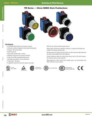
  • 1. Switches&PilotDevicesSignalingLightsRelays&SocketsTimersContactorsTerminalBlocksCircuitBreakers ø22mm - TW Series Switches & Pilot Devices 696 www.IDEC.com 1904032203 TW Series — 22mm NEMA Style Pushbuttons Key features: • TW NEMA Style Switches with snap-on contacts • Corrosion resistant octagonal chrome plated locking bezel • Snap-on 10A contact blocks • LED illumination • Slow make, double break, contacts • Modular construction for maximum flexibility • Type 4X and IP65 watertight/oiltight panel • Available assembled or as sub-components • Finger-Safe - Spring-Up • Large M3.5 screw terminals with captive sems plate IDEC has your 22mm switching needs covered. Button styles include flush, extended, mushroom, or square and all bodies are crafted from fracture-resistant nylon. All illuminated units feature two lens styles, one that maximizes light dispersion, the other accommodates direct lens engraving. Contact mechanism allow for a wide current rating, 5mA to 10A, which reduces the need for various contact materials. When looking for a 22mm switch that is durable, easy to use, and versatile, then IDEC’s TW series is your solution. UL Listed File No. E68961 CSA Approved File No. LR21451 File No. DK95-01696 Certificate No. 2030010305027380
  • 2.
  • 3. Switches&PilotDevicesSignalingLightsRelays&SocketsTimersContactorsTerminalBlocksCircuitBreakers 697800-262-IDEC (4332) • USA & Canada ø22mm - TW SeriesSwitches & Pilot Devices 1904032203 Specifications Conforming to Standards EN60947-1, EN60947-5-1, VDE0660-200, UL508, CSA C22-2 No.14 Approvals File No. E68961 File No. LR21451 Certificate No. 2030010305027380 Registration No: J9551802 (E-Stops) Registration No: J9551803 (All other switches) Registration No: J9551804 (Pilot Lights) CSA: pushbuttons and selector switches: A600 pilot lights and illuminated pushbuttons, direct supply pilot lights and illuminated pushbuttons with integral transformer (100/110, 115, 120, 200/220, 230, 240, 380, 400/440, 480V) UL: pushbuttons and selector switches: A600 pilot lights and illuminated pushbuttons, direct supply pilot lights and illuminated pushbuttons with integral transformer (100/110, 115, 120, 200/220, 230, 240, 380, 400/440, 480V) TÜV: pushbuttons and selector switches: A600=P600 (NO, NC)/Q600 (NO-EM, NC-LB) pilot lights and illuminated pushbuttons, direct supply pilot lights and illuminated pushbuttons with integral transformer (100/110, 115, 120, 200/220, 230, 240, 380, 400/440, 480V) Operating Temperature Operation: –25 to +50°C (without freezing), Storage: –40 to +80°C (without freezing) Vibration Resistance 5 to 55Hz, 100m/sec2 (10g) conforming to IEC6068-2-6 Shock Resistance 1000m/sec2 (100g) conforming to IEC6068-2-7 Electric Shock Protection Class 2 conforming to IEC60664-7 Degree of Protection (conforming to IEC60529) (conforming to NEMA ICS6-110) IP65 from front of the panel; (IP54 for key switches) IP20 (Type HW-U contact block) Type 1, 2, 3, 3R, 3S, 4, 4X, 5, 12, 13 (Type 1, 2, 3R, 5, 12, 13 for key switches) Mechanical Life Momentary pushbuttons: 5,000,000 (1800 operations per hour) All other switches: 500,000 Pollution Degree (conforming to IEC60947-1) 3 Rated Operational Characteristics AC-15: A600 or Ue = 250V, le = 3A (NO, NC, NO-EM, NC-LB) DC-13: P600 or Ue = 125V, le = 1.1A (NO, NC) DC-13: Q600 or Ue = 125V, le = 0.9A (NO-EM, NC-LB) Rated Insulation Voltage 600V Rated Switching Over-Voltage Less than 4kV, conforming to IEC60947-1 Rated Impulse Withstanding Voltage 4kV for contact circuit, 2.5kV for lamp circuit Rated Thermal Current 10 Amp Minimum Switching Capacity 5 mA at 3V AC/DC Contact Operation Slow break NC or slow make NO, self-cleaning Recommended Terminal Torque Unit Wire Number of Wires Recommended Tightening Torque (Nm) Terminal Screw HW-U Contact Block Crimping Terminal 2 1.0 to 1.3 M3.5 Solid Wire ø0.5 to 1.6 mm (AWG14 to 22) 2 1.0 to 1.3 ø1.7 to 2.0 mm (AWG12) 1 1.2 to 1.3 Stranded Wire 0.3 to 2.0 mm2 (AWG14 to 22) 2 1.0 to 1.3 2.1 to 3.5 mm2 (AWG12) 1 1.2 to 1.3 Illuminated Unit (*1) Crimping Terminal 2 1.0 to 1.3 M3.5Solid Wire ø0.5 to 1.6 mm (AWG14 to 22) Stranded Wire 0.3 to 2.0 mm (AWG14 to 22) Applicable Wire Size Pilot Light Crimping Terminal 2 0.6 to 1.0 (M3.0) 1.0 to 1.3 (M3.5) Solid Wire ø0.5 to 1.6 mm (AWG14 to 22) Stranded Wire ø0.3 to 2.0 mm (AWG14 to 22) 1. * refers to the lamp terminals of the illuminated push buttons and selector switches. External Short-Circuit Protection 10A 250V fuse conforming to IEC60269-1 Applicable Wire Size Minimum 1 x 22 AWG, max. 2 x 14 AWG or 1 x 12 AWG Contact Resistance Initial contact resistance of 50mΩ or less Contact Gap 4mm (NO and NC), 2mm (NO-EM and NC-LB) Electrical Reliability MTBF < 1 fault for 10 million operation cycles (3V DC, 5mA) Lamp Ratings LEDs: 6V: 17mA max, 12/24V: 11mA max, 120/240V: 10mA max Horsepower Rating 1/4 HP @ 120V (single-phase, non-reversing motor); 1 HP @ 240V (3 phase, non-reversing motor) Contact Material Silver ContactRatings Pushbuttons Illuminated Pushbuttons Selector Switches Illuminated Selector Switches Pushbutton Selectors Contact Block Type HW-U Rated Insulation Voltage 600V Rated Continuous Current 10A Contact Ratings by Utilization Category IEC 60947-5-1 AC-15 (A600) DC-13 (P600) Characteristics Contact Ratings by Utilization Category Operational Voltage 24V 48V 50V 110V 220V 440V Operational Current AC50/60Hz AC-12 Control of resistive loads and solid state loads 10A — 10A 10A 6A 2A AC-15 Control of electromagnetic loads (> 72VA) 10A — 7A 5A 3A 1A DC DC-12 Control of resistive loads and solid state loads 10A 5A — 2.2A 1.1A — DC-13 Control of electromagnets 5A 2A — 1.1A 0.6A —
  • 4. Switches&PilotDevicesSignalingLightsRelays&SocketsTimersContactorsTerminalBlocksCircuitBreakers ø22mm - TW Series Switches & Pilot Devices 698 www.IDEC.com 1904032203 Non-Illuminated Pushbuttons (Assembled) Assembled Pushbuttons A B ( ) W 1 10 – B Function B: Momentary O: Maintained K: Key On/Off Lock Bezel Shape Blank: Octagonal F: Full Shroud G: Mushroom Shroud Q: Square Button Color B: Black G: Green W: White R: Red S: Blue Y: Yellow Contact Arrangement 10: 1NO 01: 1NC 20: 2NO 02: 2NC 11: 1NO-1NC 22: 2NO-2NC Button Shape 1: Flush 2: Extended 3: Mushroom Head Ø 29mm 4: Mushroom Head Ø 40mm Series Designation W: TW Series To be used for interpreting part numbers only, not for part number development.
  • 5. Switches&PilotDevicesSignalingLightsRelays&SocketsTimersContactorsTerminalBlocksCircuitBreakers 699800-262-IDEC (4332) • USA & Canada ø22mm - TW SeriesSwitches & Pilot Devices 1904032203 Non-Illuminated Pushbuttons (Assembled) continued Non-Illuminated Pushbuttons Style Contacts Momentary Action Maintained Action Flush 1NO 1NC 1NO-1NC 2NO 2NC ABW110-j ABW101-j ABW111-j ABW120-j ABW102-j AOW110-j AOW101-j AOW111-j AOW120-j AOW102-j Extended 1NO 1NC 1NO-1NC 2NO 2NC ABW210-j ABW201-j ABW211-j ABW220-j ABW202-j AOW210-j AOW201-j AOW211-j AOW220-j AOW202-j Recessed 1NO 1NC 1NO-1NC 2NO 2NC ABFW110-j ABFW101-j ABFW111-j ABFW120-j ABFW102-j AOFW110-j AOFW101-j AOFW111-j AOFW120-j AOFW102-j Extended with Full Shroud 1NO 1NC 1NO-1NC 2NO 2NC ABFW210-j ABFW201-j ABFW211-j ABFW220-j ABFW202-j AOFW210-j AOFW201-j AOFW211-j AOFW220-j AOFW202-j Ø 29mm Mushroom Head 1NO 1NC 1NO-1NC 2NO 2NC ABW310-j ABW301-j ABW311-j ABW320-j ABW302-j AOW310-j AOW301-j AOW311-j AOW320-j AOW302-j Ø 40mm Mushroom Head 1NO 1NC 1NO-1NC 2NO 2NC ABW410-j ABW401-j ABW411-j ABW420-j ABW402-j AOW410-j AOW401-j AOW411-j AOW420-j AOW402-j Ø 40mm Mushroom Head with Full Shroud 1NO 1NC 1NO-1NC 2NO 2NC ABGW410-j ABGW401-j ABGW411-j ABGW420-j ABGW402-j AOGW410-j AOGW401-j AOGW411-j AOGW420-j AOGW402-j Square Flush 1NO 1NC 1NO-1NC 2NO 2NC ABQW110-j ABQW101-j ABQW111-j ABQW120-j ABQW102-j AOQW110-j AOQW101-j AOQW111-j AOQW120-j AOQW102-j Square Extended 1NO 1NC 1NO-1NC 2NO 2NC ABQW210-j ABQW201-j ABQW211-j ABQW220-j ABQW202-j AOQW210-j AOQW201-j AOQW211-j AOQW220-j AOQW202-j Keylock Push On/ Off 1NO 1NC 1NO-1NC 2NO 2NC AKW210 AKW201 AKW211 AKW220 AKW202 – 1. In place of j, specify the Button Color Code from table. 2. For sub-assembled part numbers, see next page. 3. For accessories, see page 728. 4. For dimensions, see page 730. 5. Keyed switches are supplied with two keys. All units are keyed alike. j Button Color Codes Color Code Black B Green G Red R Blue S Yellow Y White W
  • 6. Switches&PilotDevicesSignalingLightsRelays&SocketsTimersContactorsTerminalBlocksCircuitBreakers ø22mm - TW Series Switches & Pilot Devices 700 www.IDEC.com 1904032203 Non-Illuminated Pushbuttons (Sub-Assembled) Contact Blocks + Operator + Button = Complete Part Operators Style Part Number Momentary Maintained Round Flush/Extended ABW-100 AOW-100 Round with Full Shroud/Recessed ABFW-200 AOFW-200 Ø 40mm, Ø 29mm Mushroom Head ABW-300 AOW-300 Ø 40mm Mushroom Head with Full Shroud ABGW-400 AOGW-400 Square Flush/Extended ABQW-100 AOQW-100 Keylock Push On/Off — AKW-200 Buttons Style Part Number Round Flush ABW1B-j Round Extended ABW2B-j Ø 29mm Mushroom ABW3B-j Ø 40mm Mushroom ABW4B-j Square Flush ABQW1B-j Square Extended ABQW2B-j In place of j specify the button color code from table Contact Blocks Style Contacts 1NO 1NC Finger- Safe Spring-Up Terminal HW-U10-F HW-U01-F HW-U10R-F (early make) HW-U01R-F (late break) Dummy Block HW-DB 1. Dummy blocks (no contacts) are used with an odd number of contact blocks. 2. Use of early and late break contacts creates a make before break function j Button Color Codes Color Code Black B Green G Red R Blue S Yellow Y White W
  • 7. Switches&PilotDevicesSignalingLightsRelays&SocketsTimersContactorsTerminalBlocksCircuitBreakers 701800-262-IDEC (4332) • USA & Canada ø22mm - TW SeriesSwitches & Pilot Devices 1904032203 Stop Switches (Assembled) To be used for interpreting part numbers only, not for part number development. Assembled Stop Switches A V (L) W 4 (B) (99) 11 (D) – R – (24V) Function V: Pushlock Turn Reset Y: Push-Pull X: Pushlock Key Reset Illumination Blank: None L: Illuminated Series Designation W: TW Series Button/Lens Size 3: 29mm Mushroom 4: 40mm Mushroom Lens Type (illuminated units only) Blank: Standard (ribbed) B: Engravable (smooth with insert) Illuminated Circuit (illuminated unit only) 99: Full Voltage (LED determines voltage) 126: 120V AC Step Down Transformer 246: 240V AC Step Down Transformer 486: 480V AC Step Down Transformer Lamp Voltage (full voltage illuminated units only) 6V: 6V AC/DC 12V: 12V AC/DC 24V: 24V AC/DC 120V: 120V AC 240V: 240V AC Button/Lens Color A: Amber R: Red W: White G: Green S: Blue Y: Yellow B: Black Lamp Type (illuminated units only) D: LED Contact Arrangement 10: 1NO 01: 1NC 20: 2NO 02: 2NC 11: 1NO/1NC 22: 2NO/2NC
  • 8. Switches&PilotDevicesSignalingLightsRelays&SocketsTimersContactorsTerminalBlocksCircuitBreakers ø22mm - TW Series Switches & Pilot Devices 702 www.IDEC.com 1904032203 Stop Switches (Assembled), continued Non-Illuminated Stop Switches Style Contacts Part Number Ø 40mm Pushlock Turn Reset* 1NO 1NC 1NO-1NC 2NO 2NC AVW410-R* AVW401-R* AVW411-R* AVW420-R* AVW402-R* Ø 29mm Pushlock Turn Reset* 1NO 1NC 1NO-1NC 2NO 2NC AVW310-R* AVW301-R* AVW311-R* AVW320-R* AVW302-R* Ø 40mm Push-Pull 1NO 1NC 1NO-1NC 2NO 2NC AYW410-j AYW401-j AYW411-j AYW420-j AYW402-j Ø 40mm Pushlock Key Reset * 1NO 1NC 1NO-1NC 2NO 2NC AXW410- R* AXW401- R* AXW411- R* AXW420- R* AXW402- R* 1. *Available in Red only. 2. In place of j, specify the Button Color Code from table. 3. For sub-assembled part numbers, see next page. 4. For accessories, see page 728. 5. For dimensions, see page 730. Illuminated Stop Switches Style Type Contacts Part Number Ø 40mm Pushlock Turn Reset Type Transformer 1NO-1NC 2NO 2NC AVLW4 m 11D-R* AVLW4 m 20D-R* AVLW4 m 02D-R* Full Voltage 1NO-1NC 2NO 2NC AVLW49911D-R*-l AVLW49920D-R*-l AVLW49902D-R*-l Ø 29mm Pushlock Turn Reset Transformer 1NO-1NC 2NO 2NC AVLW3m11D-R* AVLW3m20D-R* AVLW3m02D-R* Full Voltage 1NO-1NC 2NO 2NC AVLW39911D-R*-l AVLW39920D-R*-l AVLW39902D-R*-l Ø 40mm Push-Pull Transformer 1NO-1NC 2NO 2NC AYLW4 m 11D-k AYLW4 m 20D-k AYLW4 m 02D-k Full Voltage 1NO-1NC 2NO 2NC AYLW49911D-k-l AYLW49920D-k-l AYLW49902D-k-l 1. *Available in red only. 2. In place of k, specify the Lens Color Code (see table above). 3. In place of l, specify the Full Voltage Code (lamp voltage) (see table above). 4. In place of m, specify the Transformer Voltage Code (see table above). 5. For sub-assembly part numbers, see next page. 6. For accessories, see page 728. 7. For dimensions, see page 730. j Button Color Codes Color Code Black B Green G Red R Blue S White W Yellow Y k LED/Lens Color Codes Color Code Amber A Green G Red R Blue S White W l Full Voltage Codes Voltage Code 6V AC/DC 6V 12V AC/DC 12V 24V AC/DC 24V 120V AC 120V 240V AC 240V m Transformer Voltage Codes Voltage Code 120VAC 240VAC 480VAC 126 246 486 Transformers step down to 6V.
  • 9. Switches&PilotDevicesSignalingLightsRelays&SocketsTimersContactorsTerminalBlocksCircuitBreakers 703800-262-IDEC (4332) • USA & Canada ø22mm - TW SeriesSwitches & Pilot Devices 1904032203 Stop Switches (Sub-Assembled) Transformer/ Adaptor* + Contacts + Lamp Holder + Operator + Lamp + Button or Lens = Complete Part *Not applicable for full voltage units Operators Style Part Number Non-Illuminated Illuminated Ø 29/Ø 40mm Pushlock Turn Reset AVW-300 AVLW3-0600 Ø 40mm Push-Pull AYW-400 AYLW4-0600 Ø 40mm Pushlock Key Reset AXW-300 — Buttons Style Part Number Ø 40mm Pushlock Turn Reset AVW4B-R* Ø 29mm Pushlock Turn Reset AVW3B-R* Ø 40mm Push-Pull AYW4B-j Ø 40mm Pushlock Key Reset AXW4B-R* 1. *Available in Red only 2. In place of j, specify the button color code from table. Lamps Style Voltage Part Number LED 6V AC/DC LSTD-6k 12V AC/DC LSTD-1k 24V AC/DC LSTD-2k 120V AC LSTD-H2k 240V AC LSTD-M4k 1. In place of k, specify the LED color code. 2. The LED contains a current-limiting resistor and a protection diode. j Button Color Codes Color Code Black B Green G Red R Blue S White W Yellow Y k LED/Lens Color Codes Color Code Amber A Green G Red R Blue S White W
  • 10. Switches&PilotDevicesSignalingLightsRelays&SocketsTimersContactorsTerminalBlocksCircuitBreakers ø22mm - TW Series Switches & Pilot Devices 704 www.IDEC.com 1904032203 Illuminated Stop Switches (Sub-Assembled) continued Lenses Style Part Number Standard Engravable Ø 29mm Head Pushlock Turn Reset AVLW3LU-R* AVLW3BLU-R* Ø 40mm Head Pushlock Turn Reset AVLW4LU-R* AVLW4BLU-R* Ø 40mm Head Push Pull AYLW4LU-k AYLW4BLU-k 1. In place of k, specify the lens color code from table on previous page. 2. *Available only in red 3. Standard lenses have ribbed pattern, Engravable lenses are smooth and include an engravable insert. Lamp Circuit Components Style Application Part Number Long Lamp Holder Used with Full-size Transformer and two contact blocks TW-LH2 Lead Holder Used with TW-LH2 holder when using four contact blocks and transformer HW-LH3 Transformers/Full Voltage Modules Style Description Part Number Full Size Transformer Finger-Safe 120V AC TW-F126B 240V AC TW-F246B 480V AC TW-F486B Dummy Block with Full Voltage Adaptor For use with odd number of contacts. Finger-Safe HW-DA1FBN Full Voltage Adaptor For use with even number of contacts. Finger-Safe TW-DA1FB All Transformers step down to 6V (use 6V LED). Contact Blocks Style Contacts 1NO 1NC Finger- Safe Spring-Up Terminal HW-U10-F HW-U01-F HW-U10R-F (early make) HW-U01R-F (late break) Dummy Block HW-DB 1. Dummy blocks (no contacts) are used with an odd number of contact blocks. 2. Use of early and late break contacts creates a make before break function
  • 11. Switches&PilotDevicesSignalingLightsRelays&SocketsTimersContactorsTerminalBlocksCircuitBreakers 705800-262-IDEC (4332) • USA & Canada ø22mm - TW SeriesSwitches & Pilot Devices 1904032203 Pilot Lights (Assembled) Assembled Pilot Lights A P (Q) W 1 (B) (99) (D) – R – (24V) Function P: Pilot Light Bezel Shape Blank: Octagonal (round lenses) Q: Square Series Designation W: TW Series Lens Shape 1: Flat 2: Dome Lens Type Blank: Standard (ribbed) B: Engravable (smooth with insert included) Illumination Circuit 99: Full Voltage (lamp determines voltage) 126: 120V AC Step Down Transformer 246: 240V AC Step Down Transformer 486: 480V AC Step Down Transformer Lamp Voltage (Full Voltage Units Only) 6V: 6V AC/DC 12V: 12V AC/DC 24V: 24V AC/DC 120V: 120V AC 240V: 240V AC Lens Color Code A: Amber G: Green R: Red S: Blue W: White Y: Yellow Lamp D: LED 1. Use only when interpreting part numbers. Do not use for developing part numbers. 2. All transformers step down to 6V.
  • 12. Switches&PilotDevicesSignalingLightsRelays&SocketsTimersContactorsTerminalBlocksCircuitBreakers ø22mm - TW Series Switches & Pilot Devices 706 www.IDEC.com 1904032203 Pilot Lights (Assembled) continued Assembled Pilot Lights Style Type Voltage Part Number Round Flat Transformer 120VAC 240VAC 480VAC APW1126D-k APW1246D-k APW1486D-k Full Voltage — APW199D-k-l Dome Transformer 120VAC 240VAC 480VAC APW2126D-k APW2246D-k APW2486D-k Full Voltage — APW299D-k-l Square Flat Transformer 120VAC 240VAC 480VAC APQW1B126D-k APQW1B246D-k APQW1B486D-k Full Voltage — APQW1B99D-k-l 1. In place of k, specify the Lens Color Code from table below. 2. In place of l, specify the Full Voltage Code from table below. 3. For accessories, see page 728. 4. For dimensions, see page 730. 5. For sub-assembly part numbers, see next page. 6. Yellow pilot light comes with white LED. k Lens Color Codes Color Code Amber A Green G Red R Blue S White W Yellow Y l Full Voltage Codes Voltage Code 6V AC/DC 6V 12V AC/DC 12V 24V AC/DC 24V 120V AC 120V 240V AC 240V
  • 13. Switches&PilotDevicesSignalingLightsRelays&SocketsTimersContactorsTerminalBlocksCircuitBreakers 707800-262-IDEC (4332) • USA & Canada ø22mm - TW SeriesSwitches & Pilot Devices 1904032203 Pilot Lights (Sub-Assembled) Transformer + Operator + Lamp + Lens = Complete Part * Transformer not required for full voltage units. Operators Style Part Number Round Dome/Flat APW-199 Square UPQW-199 Same operator is used for full voltage as for transformer completed units. Lenses Style Part Number Standard Engravable Dome APW2LU-k — Round Flat APW1LU-k APW1BLU-k Square Flat — APQW1BLU-k 1. In place of k, specify the Lens Color Code from table. 2. Standard lenses have a ribbed lens to enhance light dispersion. Marking lenses are smooth and include an engravable insert. Lamps Style Voltage Part Number LED 6V AC/DC LSTD-6k 12V AC/DC LSTD-1k 24V AC/DC LSTD-2k 120V AC LSTD-H2k 240V AC LSTD-M4k 1. In place of k, specify the LED color code. 2. The LED contains a current-limiting resistor and a protection diode. 3. Yellow LED not available. Use white LED. Transformers Style Description Part Number Finger-Safe 120V AC TW-F126B 240V AC TW-F246B 480V AC TW-F486B All Transformers step down to 6V (use 6V LED). k LED/Lens Color Codes Color Code Amber A Green G Red R Blue S White W Yellow Y If clear lens is desired, use white marking lens and remove engraving insert
  • 14. Switches&PilotDevicesSignalingLightsRelays&SocketsTimersContactorsTerminalBlocksCircuitBreakers ø22mm - TW Series Switches & Pilot Devices 708 www.IDEC.com 1904032203 Illuminated Pushbuttons (Assembled) Assembled Illuminated Pushbuttons A L (F) W 2 (B) 99 11 (D) – R – (24V) Function L: Momentary Action OL: Maintained Action Bezel Shape Blank: Octagonal (round lenses) F: Full Shroud (round lenses) Q: Square Series Designation W: TW series Lens Shape/Size 2: Standard Extended (round or square) 3: 29mm Mushroom 4: 40mm Mushroom Lens Type Blank: Standard (ribbed) B: Engravable (smooth with insert) Illumination Circuit 99: Full Voltage (lamp determines voltage) 126: 120V AC Step Down Transformer 246: 240V AC Step Down Transformer 486: 480V AC Step Down Transformer Lamp Voltage (Full Voltage Units Only) 6V: 6V AC/DC 12V: 12V AC/DC 24V: 24V AC/DC 120V: 120V AC 240V: 240V AC Lens Code A: Amber G: Green R: Red S: Blue W: White Y: Yellow Lamp Type D: LED Lamp Contact Arrangement 10: 1NO 01: 1NC 20: 2NO 02: 2NC 11: 1NO-1NC 22: 2NO-2NC 1. Use only when interpreting part numbers. Do not use for developing part numbers. 2. Transformers step down to 6V.
  • 15. Switches&PilotDevicesSignalingLightsRelays&SocketsTimersContactorsTerminalBlocksCircuitBreakers 709800-262-IDEC (4332) • USA & Canada ø22mm - TW SeriesSwitches & Pilot Devices 1904032203 Illuminated Pushbuttons (Assembled) Illuminated Pushbuttons Style Contacts Part Number Momentary Maintained Extended Lens Transformer 1NO-1NC 2NO 2NC ALW2 m 11D-k ALW2 m 20D-k ALW2 m 02D-k AOLW2 m 11D-k AOLW2 m 20D-k AOLW2 m 02D-k Full Voltage 1NO-1NC 2NO 2NC ALW29911D-k-l ALW29920D-k-l ALW29902D-k-l AOLW29911D-k-l AOLW29920D-k-l AOLW29902D-k-l Extended Lens with Full Shroud Transformer 1NO-1NC 2NO 2NC ALFW2 m 11D-k ALFW2 m 20D-k ALFW2 m 02D-k AOLFW2 m 11D-k AOLFW2 m 20D-k AOLFW2 m 02D-k Full Voltage 1NO-1NC 2NO 2NC ALFW29911D-k-l ALFW29920D-k-l ALFW29902D-k-l AOLFW29911D-k-l AOLFW29920D-k-l AOLFW29902D-k-l ø29mm Mushroom Button Transformer 1NO-1NC 2NO 2NC ALW3 m 11D-k ALW3 m 20D-k ALW3 m 02D-k AOLW3 m11D-k AOLW3 m20D-k AOLW3 m 02D-k Full Voltage 1NO-1NC 2NO 2NC ALW39911D-k-l ALW39920D-k-l ALW39902D-k-l AOLW39911D-k-l AOLW39920D-k-l AOLW39902D-k-l ø40mm Mushroom Button Transformer 1NO-1NC 2NO 2NC ALW4 m 11D-k ALW4 m 20D-k ALW4 m 02D-k AOLW4 m11D-k AOLW4 m20D-k AOLW4 m 02D-k Full Voltage 1NO-1NC 2NO 2NC ALW49911D-k-l ALW49920D-k-l ALW49902D-k-l AOLW49911D-k-l AOLW49920D-k-l AOLW49902D-k-l Square Extended Transformer 1NO-1NC 2NO 2NC ALQW2B m11D-k ALQW2B m20D-k ALQW2B m02D-k AOLQW2B m11D-k AOLQW2B m20D-k AOLQW2B m02D-k Full Voltage 1NO-1NC 2NO 2NC ALQW2B9911D-k-l ALQW2B9920D-k-l ALQW2B9902D-k-l AOLQW2B9911D-k-l AOLQW2B9920D-k-l AOLQW2B9902D-k-l 1. In place of k, specify the Lens Color Code (see table). Mushroom lenses not available in yellow. 2. In place of l, specify the Full Voltage Code (lamp voltage) (see table). 3. In place of m, specify the Transformer Voltage Code (see table). 4. For sub-assembly part numbers, see next page. 5. For accessories, see page 728. 6. For dimensions, see page 730. 7. Light is independent of switch position. 8. Yellow pushbutton comes with white LED. k LED/Lens Color Codes Color Code Amber A Green G Red R Blue S White W Yellow Y 1. Mushroom lenses not available in yellow. 2. Yellow pushbutton comes with white LED. l Full Voltage Codes Voltage Code 6V AC/DC 6V 12V AC/DC 12V 24V AC/DC 24V 120V AC 120V 240V AC 240V m Transformer Voltage Codes Voltage Code 120VAC 126 240VAC 246 480VAC 486 Transformers step down to 6V (use 6V LED).
  • 16. Switches&PilotDevicesSignalingLightsRelays&SocketsTimersContactorsTerminalBlocksCircuitBreakers ø22mm - TW Series Switches & Pilot Devices 710 www.IDEC.com 1904032203 Illuminated Pushbuttons (Sub-Assembled) Transformer/ Adaptor* + Contacts + Lamp Holder + Operator + Lamp + Lens = Complete Part *Not applicable for full voltage units Operators Style Part Number Momentary Maintained Extended ALW-0600 AOLW-0600 Extended with Full Shroud ALFW-0600 AOLFW-0600 ø29mm/ø40mm Mushroom ALW3-0600 AOLW3-0600 Square/Extended ALQW-2B0600 AOLQW-2B0600 Lenses Style Part Number Standard Engravable Round Extended ALW2LU-k ALW2BLU-k ø 29mm Mushroom Head* ALW3LU-k ALW3BLU-k ø 40mm Mushroom Head* ALW4LU-k ALW4BLU-k Square Extended — ALQW2BLU-k 1. In place of k, specify the lens color code from table on the bottom right. 2. *Mushroom lens not available in yellow. 3. Standard lenses have ribbed pattern, Engravable lenses are smooth and include an engravable insert. Lamps Style Voltage Part Number LED 6V AC/DC LSTD-6k 12V AC/DC LSTD-1k 24V AC/DC LSTD-2k 120V AC LSTD-H2k 240V AC LSTD-M4k 1. In place of k, specify the LED color code. 2. The LED contains a current-limiting resistor and a protection diode. Lamp Circuit Components Style Application Part Number Long Lamp Holder Used with Full-size Transformer and two contact blocks TW-LH2 Lead Holder Used with TW-LH2 holder when using four contact blocks and transformer HW-LH3 k LED/Lens Color Codes Color Code Color Code Amber A Blue S Green G White W Red R Yellow Y Yellow LED not available. Use white LED.
  • 17. Switches&PilotDevicesSignalingLightsRelays&SocketsTimersContactorsTerminalBlocksCircuitBreakers 711800-262-IDEC (4332) • USA & Canada ø22mm - TW SeriesSwitches & Pilot Devices 1904032203 Illuminated Pushbuttons (Sub-Assembled) continued Contact Blocks Style Contacts 1NO 1NC Finger- Safe Spring-Up Terminal HW-U10-F HW-U01-F HW-U10R-F (early make) HW-U01R-F (late break) Dummy Block HW-DB 1. Dummy blocks (no contacts) are used with an odd number of contact blocks. 2. Use of early and late break contacts creates a make before break function Transformers/Full Voltage Modules Style Description Part Number Full Size Transformer Finger-Safe 120V AC TW-F126B 240V AC TW-F246B 480V AC TW-F486B Dummy Block with Full Voltage Adaptor For use with odd number of contacts. Finger-Safe HW-DA1FBN Full Voltage Adaptor For use with even number of contacts. Finger-Safe TW-DA1FB All Transformers step down to 6V (use 6V LED).
  • 18. Switches&PilotDevicesSignalingLightsRelays&SocketsTimersContactorsTerminalBlocksCircuitBreakers ø22mm - TW Series Switches & Pilot Devices 712 www.IDEC.com 1904032203 Non-Illuminated Selector Switches (Assembled) Assembled Selector Switches A S W 3 (1) (L) 20 – 304 Function S: Selector Switch Series Designation W: TW Series Number of Positions 2: 2-Position 3: 3-Position 4: 4-Position 5: 5-Position Spring Return Action Blank: Maintained 1: Spring return from Right (2 or 3 position) 2: Spring return from Left (2 or 3 position) 3: 2-Way spring return from Left and Right (3 position only) Circuit Number (Standard circuits shown on following pages and 720.) Contact Arrangement Code 10: 1NO 01: 1NC 20: 2NO 02: 2NC 40: 4NO 04: 4NC 11: 1NO-1NC 22: 2NO-2NC Operator Style Code Blank: Knob Operator L: Lever Operator K: Key Operator 1. Use only when interpreting part numbers. Do not use for developing part numbers. 2. Custom contact configurations available. 3. Custom key removable codes available. 4. Portions of part number inside ( ) are optional.
  • 19. Switches&PilotDevicesSignalingLightsRelays&SocketsTimersContactorsTerminalBlocksCircuitBreakers 713800-262-IDEC (4332) • USA & Canada ø22mm - TW SeriesSwitches & Pilot Devices 1904032203 Non-Illuminated Selector Switches (Assembled) continued 2-Position Selector Switches Style Part Number Contact Mounting Operator Position Maintained Spring Return from Right Spring Return from Left L R L R L R L R 1NO 1 2 O O X O Knob Lever Key ASW210 ASW2L10 ASW2K10 ASW2110 ASW21L10 ASW21K10 ASW2210 ASW22L10 ASW22K10 1NC 1 2 X O O O Knob Lever Key ASW201-116 ASW2L01-116 ASW2K01-116 ASW2101-116 ASW21L01-116 ASW21K01-116 ASW2201-116 ASW22L01-116 ASW22K01-116 1NO 1NC 1 2 X O O X Knob Lever Key ASW211 ASW2L11 ASW2K11 ASW2111 ASW21L11 ASW21K11 ASW2211 ASW22L11 ASW22K11 2NO 1 2 O O X X Knob Lever Key ASW220 ASW2L20 ASW2K20 ASW2120 ASW21L20 ASW21K20 ASW2220 ASW22L20 ASW22K20 2NC 1 2 X X O O Knob Lever Key ASW202-104 ASW2L02-104 ASW2K02-104 ASW2102-104 ASW21L02-104 ASW21K02-104 ASW2202-104 ASW22L02-104 ASW22K02-104 2NO 2NC 1 2 3 4 O X O X X O X O Knob Lever Key ASW222 ASW2L22 ASW2K22 ASW2122 ASW21L22 ASW21K22 ASW2222 ASW22L22 ASW22K22 2NO 2NC 1 2 3 4 O O X X X X O O Knob Lever Key ASW222-111 ASW2L22-111 ASW2K22-111 ASW2122-111 ASW21L22-111 ASW21K22-111 ASW2222-111 ASW22L22-111 ASW22K22-111
  • 20. Switches&PilotDevicesSignalingLightsRelays&SocketsTimersContactorsTerminalBlocksCircuitBreakers ø22mm - TW Series Switches & Pilot Devices 714 www.IDEC.com 1904032203 Non-Illuminated Selector Switches (Assembled) continued 3-Position Selector Switches Style Part Number Contact Mounting Operator Position Maintained Spring Return from Right Spring Return from Left Spring Return Two-Way L C R L C R L C R L C R L C R 2NO 1 2 X O O O O X Knob Lever Key ASW320 ASW3L20 ASW3K20 ASW3120 ASW31L20 ASW31K20 ASW3220 ASW32L20 ASW32K20 ASW3320 ASW33L20 ASW33K20 2NC 1 2 O X X X X O Knob Lever Key ASW302 ASW3L02 ASW3K02 ASW3102 ASW31L02 ASW31K02 ASW3202 ASW32L02 ASW32K02 ASW3302 ASW33L02 ASW33K02 2NO 2NC 1 2 3 4 X O O X O O X X O X X O Knob Lever Key ASW322 ASW3L22 ASW3K22 ASW3122 ASW31L22 ASW31K22 ASW3222 ASW32L22 ASW32K22 ASW3322 ASW33L22 ASW33K22 2NO 2NC 1 2 3 4 X X O O O X X O X O O X Knob Lever Key ASW322-309 ASW3L22-309 ASW3K22-309 ASW3122-309 ASW31L22-309 ASW31K22-309 ASW3222-309 ASW32L22-309 ASW32K22-309 ASW3322-309 ASW33L22-309 ASW33K22-309 2NO 2NC 1 2 3 4 O O O O X O X O O X O X Knob Lever Key ASW322-310 ASW3L22-310 ASW3K22-310 ASW3122-310 ASW31L22-310 ASW31K22-310 ASW3222-310 ASW32L22-310 ASW32K22-310 ASW3322-310 ASW33L22-310 ASW33K22-310 4NO 1 2 3 4 X O X O O O O O O X O X Knob Lever Key ASW340 ASW3L40 ASW3K40 ASW3140 ASW31L40 ASW31K40 ASW3240 ASW32L40 ASW32K40 ASW3340 ASW33L40 ASW33K40 4NC 1 2 3 4 O X O X X X X X X O X O Knob Lever Key ASW304 ASW3L04 ASW3K04 ASW3104 ASW31L04 ASW31K04 ASW3204 ASW32L04 ASW32K04 ASW3304 ASW33L04 ASW33K04 1. The truth table indicates the operating position of contact block when the operator is switched to that position. X = On (closed contacts) O = Off (open contacts) X X = Overlapping Contacts: Remain on (closed contacts) when switch is moved between these two positions. 2. All knob and lever selector switches come in black. Other colors are available by ordering the knob or lever separately. 3. Every key selector switch uses an identical key. The key is removable in any maintained position. 4. Custom contact configurations are available, see page 720. 4-Position Selector Switch Style Maintained Contact Mounting Operator Position Part Number 1 2 3 4 1 2 3 4 2NO 2NC 1 2 3 4 X O O O O X O O O O X O O O O X Knob Lever ASW422-411 ASW4L22-411 5-Position Selector Switch Style Maintained Contact Mounting Operator Position Part Number 1 2 3 4 5 1 2 3 4 5 2NO 2NC 1 2 3 4 X O O O O X O O O O O O O O X O O O O X Knob Lever ASW522-501 ASW5L22-501
  • 21. Switches&PilotDevicesSignalingLightsRelays&SocketsTimersContactorsTerminalBlocksCircuitBreakers 715800-262-IDEC (4332) • USA & Canada ø22mm - TW SeriesSwitches & Pilot Devices 1904032203 Non-Illuminated Selector Switches (Sub-Assembled) Contact Blocks + Operator + Knob or Lever* + Color Insert* = Complete Part† 1. *Not needed with key type switches. 2. † Knob type shown. Operators Style Positions Description Part Number Knob/Lever 2 Maintained ASW200 Spring return from right ASW2100 Spring return from left ASW2200 3 Maintained, Cam 1 Maintained, Cam 2 Maintained, Cam 3 ASW300-1 ASW300-2 ASW300-3 Spring return from right, Cam 1 Spring return from right, Cam 2 ASW3100-1 ASW3100-2 Spring return from left, Cam 1 Spring return from left, Cam 2 ASW3200-1 ASW3200-2 Spring return from left/right, Cam 1 Spring return from left/right, Cam 2 ASW3300-1 ASW3300-2 4 Maintained, Standard Cam Maintained, Cam 1 ASW400 ASW400-1 5 Maintained, Standard cam Maintained, Cam 1 ASW500 ASW500-1 Key 2 Maintained ASW2K00 Spring return from right ASW21K00 Spring return from left ASW22K00 3 Maintained, Cam 1 Maintained, Cam 2 Maintained, Cam 3 ASW3K00-1 ASW3K00-2 ASW3K00-3 Spring return from right, Cam 1 Spring return from right, Cam 2 ASW31K00-1 ASW31K00-2 Spring return from left, Cam 1 Spring return from left, Cam 2 ASW32K00-1 ASW32K00-2 Spring return from left/right, Cam 1 Spring return from left/right, Cam 2 ASW33K00-1 ASW33K00-2 1. Two keys are supplied with every key switch, all are keyed alike, and removable from any maintained position. 2. Locking rings are included with all operators. Order knobs, levers, and color inserts separately. 3. Different cams produce different contact actions. For details, see page 720. 4. Key switch operator supplied with black sleeve. Handles and Inserts Style Part Number Knob ASWHHY-j Lever ASWHHL-j Color Insert TW-HC1-j Contact Blocks Style Contacts 1NO 1NC Finger- Safe Spring-Up Terminal HW-U10-F HW-U01-F HW-U10R-F (early make) HW-U01R-F (late break) Dummy Block HW-DB 1. Push rod color code: Green = NO contact block Red = NC contact block. 2. Dummy blocks (no contacts) are used with an odd number of contact blocks. j Handle/Insert Color Codes Color Code Black* B Blue S Green G Red R Yellow Y White† W *Color inserts not available in black. † Knob and lever not available in white. Replacement Parts Key Switch Black Sleeve AKW2B-B
  • 22. Switches&PilotDevicesSignalingLightsRelays&SocketsTimersContactorsTerminalBlocksCircuitBreakers ø22mm - TW Series Switches & Pilot Devices 716 www.IDEC.com 1904032203 Illuminated Selector Switches (Assembled) Assembled Illuminated Selector Switches A SL W 2 (2) 99 11 (D) – (103) – R – (24V) Function SL: Illuminated Selector Switch Series Designation W: TW series Number of Positions 2: 2-Position 3: 3-Position Spring Return Action Blank: Maintained 1: Spring return from Right 2: Spring return from Left 3: Two-Way spring return from Left and Right Illumination Circuit 99: Full Voltage (lamp determines voltage) 126: 120V AC Step Down Transformer 246: 240V AC Step Down Transformer 486: 480V AC Step Down Transformer Lamp Voltage (Full Voltage Units Only) 6V: 6V AC/DC 12V: 12V AC/DC 24V: 24V AC/DC 120V: 120V AC 240V: 240V AC Lens Color Code A: Amber G: Green R: Red S: Blue W: White Y: Yellow Contact Circuit Number Standard circuits are listed on the following pages and 720. Lamp Type D: LED Lamp Contact Arrangement 10: 1NO 01: 1NC 20: 2NO 02: 2NC 40: 4NO 04: 4NC 11: 1NO-1NC 22: 2NO-2NC 1. Use only when interpreting part numbers. Do not use for developing part numbers. 2. All transformers step down to 6V (use 6V lamp).
  • 23. Switches&PilotDevicesSignalingLightsRelays&SocketsTimersContactorsTerminalBlocksCircuitBreakers 717800-262-IDEC (4332) • USA & Canada ø22mm - TW SeriesSwitches & Pilot Devices 1904032203 Illuminated Selector Switches(Assembled) continued Illuminated 2-Position Selector Switches Style Part Number Contact Mounting Operator Position Lamp Circuit Type Maintained Spring Return from Right Spring Return from Left L R L R L RL R 1NO 1NC 1 2 O X X O Transformer Full Voltage ASLW2 j 11D-k ASLW29911D-k-l ASLW21 j 11D-k ASLW219911D-k-l ASLW22 j 11D-k ASLW229911D-k-l 2NO 1 2 O O X X Transformer Full Voltage ASLW2 j 20D-k ASLW29920D-k-l ASLW21 j 20D-k ASLW219920D-k-l ASLW22 j 20D-k ASLW229920D-k-l 2NC 1 2 X X O O Transformer Full Voltage ASLW2 j 02D-104-k ASLW29902D-104-k-l ASLW21 j 02D-104-k ASLW219902D-104-k-l ASLW22 j 02D-104-k ASLW229902D-104-k-l 2NO 2NC 1 2 3 4 O X O X X O X O Transformer Full Voltage ASLW2 j 22D-k ASLW29922D-k-l ASLW21 j 22D-k ASLW219922D-k-l ASLW22 j 22D-k ASLW229922D-k-l Illuminated 3-Position Selector Switches, Maintained and Spring Return from Right Style Part Number Contact Mounting Operator Position Lamp Circuit Type Maintained Spring Return From Right Spring Return from Left Spring Return Two-Way L C R L C R L C R L C R L C R 2NO 1 2 X O O O O X Transformer Full Voltage ASLW3 j 20D-k ASLW39920D-k-l ASLW31 j 20D-k ASLW319920D-k-l ASLW32 j 20D-k ASLW329920D-k-l ASLW33 j 20D-k ASLW339920D-k-l 2NC 1 2 O X X X X O Transformer Full Voltage ASLW3 j 02D-k ASLW39902D-k-l ASLW31 j 02D-k ASLW319902D-k-l ASLW32 j 02D-k ASLW329902D-k-l ASLW33 j 02D-k ASLW339902D-k-l 2NO 2NC 1 2 3 4 X O O X O O X X O X X O Transformer Full Voltage ASLW3 j 22D-k ASLW39922D-k-l ASLW31 j 22D-k ASLW319922D-k-l ASLW32 j 22D-k ASLW329922D-k-l ASLW33 j 22D-k ASLW339922D-k-l 2NO 2NC 1 2 3 4 X X O O O X X O X O O X Transformer Full Voltage ASLW3 j 22D-309-k ASLW39922D-309-k-l ASLW31 j 22D-309-k ASLW319922D-309-k-l ASLW32 j 22D-309-k ASLW329922D-309-k-l ASLW33 j 22D-309-k ASLW339922D-309-k-l 2NO 2NC 1 2 3 4 O O O O X O X O O X O X Transformer Full Voltage ASLW3 j 22D-310-k ASLW39922D-310-k-l ASLW31 j 22D-310-k ASLW319922D-310-k-l ASLW32 j 22D-310- k ASLW329922D-310- k -l ASLW33 j 22D-310-k ASLW339922D-310-k-l 4NO 1 2 3 4 X O X O O O O O O X O X Transformer Full Voltage ASLW3 j 40D-k ASLW39940D-k-l ASLW31 j 40D-k ASLW319940D-k-l ASLW32 j 40D-k ASLW329940D-k-l ASLW33 j 40D-k ASLW339940D-k-l 4NC 1 2 3 4 O X O X X X X X X O X O Transformer Full Voltage ASLW3 j 04D-k ASLW39904D-k-l ASLW31 j 04D-k ASLW319904D-k-l ASLW32 j 04D-k ASLW329904D-k-l ASLW33 j 04D-k ASLW339904D-k-l 1. In place of j, specify the Transformer Voltage Code. 2. In place of k, specify the Lens/LED Color Code. 3. In place of l, specify the Full Voltage Code. 4. For custom contact configurations, see page 720. 5. Light is independent of switch position. 6. Yellow selector switch comes with white LED. l Full Voltage Codes Voltage Code 6V AC/DC 6V 12V AC/DC 12V 24V AC/DC 24V 120V AC 120V 240V AC 240V j Transformer Voltage Codes Voltage Code 120VAC 126 240VAC 246 480VAC 486 Transformers step down to 6V (use 6V LED). k LED/Lens Color Codes Color Code Amber A Green G Red R Blue S White W Yellow Y
  • 24. Switches&PilotDevicesSignalingLightsRelays&SocketsTimersContactorsTerminalBlocksCircuitBreakers ø22mm - TW Series Switches & Pilot Devices 718 www.IDEC.com 1904032203 Illuminated Selector Switches (Sub-Assembled) Transformer* + Contact Block + Operator + Lamp/Lead Holder† + LED + Lens = Complete Part *Full voltage units use a full voltage adaptor TW-DA1FB (even number of blocks) OR HW-DA1FBN (odd number of blocks) instead of a transformer. † Lamp holder is not included with operators, order separately. Operators Style Positions Description Part Number 2 Maintained ASLW200 Spring return from right ASLW2100 Spring return from left ASLW2200 3 Maintained, cam 1 Maintained, cam 2 Maintained, cam 3 ASLW300-1 ASLW300-2 ASLW300-3 Spring return from right, cam 1 Spring return from right, cam 2 ASLW3100-1 ASLW3100-2 Spring return from left, cam 1 Spring return from left, cam 2 ASLW3200-1 ASLW3200-2 Spring return from left/right, cam 1 Spring return from left/right, cam 2 ASLW3300-1 ASLW3300-2 Different cams produce different contact action. For details, see Contact Arrangements on page 720. Lenses (Knobs) Style Part Number Knob ASLWLU-k In place of k, specify the lens color code from table. Lamps Style Voltage Part Number LED 6V AC/DC LSTD-6k 12V AC/DC LSTD-1k 24V AC/DC LSTD-2k 120V AC LSTD-H2k 240V AC LSTD-M4k 1. In place of k, specify the LED color code. 2. The LED contains a current-limiting resistor and a protection diode. k LED/Lens Color Codes Color Code Amber A Green G Red R Blue S White W Yellow Y Yellow LED not available. Use white LED
  • 25. Switches&PilotDevicesSignalingLightsRelays&SocketsTimersContactorsTerminalBlocksCircuitBreakers 719800-262-IDEC (4332) • USA & Canada ø22mm - TW SeriesSwitches & Pilot Devices 1904032203 Illuminated Selector Switches (Sub-Assembled) continued Contact Blocks Style Contacts 1NO 1NC Finger- Safe Spring-Up Terminal HW-U10-F HW-U01-F HW-U10R-F (early make) HW-U01R-F (late break) Dummy Block HW-DB 1. Dummy blocks (no contacts) are used with an odd number of contact blocks. 2. Use of early and late break contacts creates a make before break function Lamp Circuit Components Style Application Part Number Short Lamp Holder Used with full voltage adaptor and one contact block TW-LH1 Long Lamp Holder Used with Full-size Transformer and two contact blocks TW-LH2 Lead Holder Used with TW-LH2 holder when using four contact blocks and full size transformer HW-LH3 Transformers/Full Voltage Modules Style Description Part Number Full Size Transformer Finger-Safe 120V AC TW-F126B 240V AC TW-F246B 480V AC TW-F486B Dummy Block with Full Voltage Adaptor For use with odd number of contacts. Finger-Safe HW-DA1FBN Full Voltage Adaptor For use with even number of contacts. Finger-Safe TW-DA1FB All Transformers step down to 6V (use 6V lamp).
  • 26. Switches&PilotDevicesSignalingLightsRelays&SocketsTimersContactorsTerminalBlocksCircuitBreakers ø22mm - TW Series Switches & Pilot Devices 720 www.IDEC.com 1904032203 Contact Arrangement Charts How to Read Contact Arrangement Charts To determine contact block mounting position, first make sure the selector switch is oriented as shown on the right Contact Arrangement Type and quantity of switch contacts Circuit Number * N/D = No designation required Contact Block Mounting Position Position or mounting contact blocks on operator. Operator Position Truth table indicates the operating position of contact block when operator is switched to that position (X - closed, O - open). Contact Block Part Number Part number to use when ordering sub-assembly contact blocks, as required for use with corresponding mounting position Contact Arrangement Chart: 2-Position Selector Switches Style Mounting Position Operator Position Contact Block Part Number Description Operator Part Number Contact Circuit Number Maintained Spring Ret. from Rt. Spring Ret. from Lt. L R L R L R L R 1NO N/D 1 O X HW-U10-F Knob/Lever Key Illuminated Knob ASW200 ASW2K00 ASLW200 ASW2100 ASW21K00 ASLW2100 ASW2200 ASW22K00 ASLW22002 O O HW-DB 1NC 116 1 X O HW-U01-F Knob/Lever Key Illuminated Knob ASW200 ASW2K00 ASLW200 ASW2100 ASW21K00 ASLW2100 ASW2200 ASW22K00 ASLW22002 O O HW-DB 1NO 1NC N/D 1 O X HW-U10-F Knob/Lever Key Illuminated Knob ASW200 ASW2K00 ASLW200 ASW2100 ASW21K00 ASLW2100 ASW2200 ASW22K00 ASLW22002 X O HW-U01-F 103 1 X O HW-U01-F Knob/Lever Key Illuminated Knob ASW200 ASW2K00 ASLW200 ASW2100 ASW21K00 ASLW2100 ASW2200 ASW22K00 ASLW22002 O X HW-U10-F 1NO-EM 1NC-LB 600 1 O X HW-U10R-F Knob/Lever Key Illuminated Knob ASW200 ASW2K00 ASLW200 ASW2100 ASW21K00 ASLW2100 ASW2200 ASW22K00 ASLW22002 X O HW-U01R-F 601 1 X O HW-U01R-F Knob/Lever Key Illuminated Knob ASW200 ASW2K00 ASLW200 ASW2100 ASW21K00 ASLW2100 ASW2200 ASW22K00 ASLW22002 O X HW-U10R-F 2NO N/D 1 O X HW-U10-F Knob/Lever Key Illuminated Knob ASW200 ASW2K00 ASLW200 ASW2100 ASW21K00 ASLW2100 ASW2200 ASW22K00 ASLW22002 O X HW-U10-F 2NC 104 1 X O HW-U01-F Knob/Lever Key Illuminated Knob ASW200 ASW2K00 ASLW200 ASW2100 ASW21K00 ASLW2100 ASW2200 ASW22K00 ASLW22002 X O HW-U01-F 2NO 2NC N/D 1 O X HW-U10-F Knob/Lever Key Illuminated Knob ASW200 ASW2K00 ASLW200 ASW2100 ASW21K00 ASLW2100 ASW2200 ASW22K00 ASLW2200 2 X O HW-U01-F 3 O X HW-U10-F 4 X O HW-U01-F 111 1 O X HW-U10-F Knob/Lever Key Illuminated Knob ASW200 ASW2K00 ASLW200 ASW2100 ASW21K00 ASLW2100 ASW2200 ASW22K00 ASLW2200 2 O X HW-U10-F 3 X O HW-U01-F 4 X O HW-U01-F 1. NO-EM, NC-LB = Early Make, Late Break. N/D = No circuit number designation required in assembled selector switch part number. 2. X = On (closed contacts) O = Off (Open contacts) L 3 4 1 2 R
  • 27. Switches&PilotDevicesSignalingLightsRelays&SocketsTimersContactorsTerminalBlocksCircuitBreakers 721800-262-IDEC (4332) • USA & Canada ø22mm - TW SeriesSwitches & Pilot Devices 1904032203 Contact Arrangement Chart: 3-Position Selector Switches Style Mounting Position Operator Position Contact Block Part Number Description Operator Part Number Contact Circuit Number Maintained Spring Return from Right Spring Return from Left Two-Way L C R L C R L C R L C R L C R 1NO 1NC 202 1 X 0 0 HW-U10-F Knob/Lever Key Illuminated Knob ASW300-1 ASW3K00-1 ASLW300-1 ASW3100-1 ASW31K00-1 ASLW3100-1 ASW3200-1 ASW32K00-1 ASLW3200-1 ASW3300-1 ASW33K00-1 ASLW3300-12 X X O HW-U01-F 203 1 0 X X HW-U01-F Knob/Lever Key Illuminated Knob ASW300-1 ASW3K00-1 ASLW300-1 ASW3100-1 ASW31K00-1 ASLW3100-1 ASW3200-1 ASW32K00-1 ASLW3200-1 ASW3300-1 ASW33K00-1 ASLW3300-12 O 0 X HW-U10-F 302 1 X 0 X HW-U10-F Knob/Lever Key Illuminated Knob ASW300-2 ASW3K00-2 ASLW300-2 ASW3100-2 ASW31K00-2 ASLW3100-2 ASW3200-2 ASW32K00-2 ASLW3200-2 ASW3300-2 ASW33K00-2 ASLW3300-22 X X O HW-U01-F 303 1 0 X O HW-U01-F Knob/Lever Key Illuminated Knob ASW300-2 ASW3K00-2 ASLW300-2 ASW3100-2 ASW31K00-2 ASLW3100-2 ASW3200-2 ASW32K00-2 ASLW3200-2 ASW3300-2 ASW33K00-2 ASLW3300-22 O 0 X HW-U10-F 2NO N/D 1 X 0 0 HW-U10-F Knob/Lever Key Illuminated Knob ASW300-1 ASW3K00-1 ASLW300-1 ASW3100-1 ASW31K00-1 ASLW3100-1 ASW3200-1 ASW32K00-1 ASLW3200-1 ASW3300-1 ASW33K00-1 ASLW3300-12 O 0 X HW-U10-F 301 1 X 0 X HW-U10-F Knob/Lever Key Illuminated Knob ASW300-2 ASW3K00-2 ASLW300-2 ASW3100-2 ASW31K00-2 ASLW3100-2 ASW3200-2 ASW32K00-2 ASLW3200-2 ASW3300-2 ASW33K00-2 ASLW3300-22 O 0 X HW-U10-F 2NC 304 1 0 X O HW-U01-F Knob/Lever Key Illuminated Knob ASW300-2 ASW3K00-2 ASLW300-2 ASW3100-2 ASW31K00-2 ASLW3100-2 ASW3200-2 ASW32K00-2 ASLW3200-2 ASW3300-2 ASW33K00-2 ASLW3300-22 X X O HW-U01-F N/D 1 0 X X HW-U01-F Knob/Lever Key Illuminated Knob ASW300-1 ASW3K00-1 ASLW300-1 ASW3100-1 ASW31K00-1 ASLW3100-1 ASW3200-1 ASW32K00-1 ASLW3200-1 ASW3300-1 ASW33K00-1 ASLW3300-12 X X O HW-U01-F 2NO 2NC N/D 1 X 0 0 HW-U10-F Knob/Lever Key Illuminated Knob ASW300-1 ASW3K00-1 ASLW300-1 ASW3100-1 ASW31K00-1 ASLW3100-1 ASW3200-1 ASW32K00-1 ASLW3200-1 ASW3300-1 ASW33K00-1 ASLW3300-1 2 0 0 X HW-U10-F 3 0 X X HW-U01-F 4 X X 0 HW-U01-F 210 1 0 X X HW-U01-F Knob/Lever Key Illuminated Knob ASW300-1 ASW3K00-1 ASLW300-1 ASW3100-1 ASW31K00-1 ASLW3100-1 ASW3200-1 ASW32K00-1 ASLW3200-1 ASW3300-1 ASW33K00-1 ASLW3300-1 2 0 0 X HW-U10-F 3 0 X X HW-U01-F 4 0 0 X HW-U10-F 308 1 X 0 X HW-U10-F Knob/Lever Key Illuminated Knob ASW300-2 ASW3K00-2 ASLW300-2 ASW3100-2 ASW31K00-2 ASLW3100-2 ASW3200-2 ASW32K00-2 ASLW3200-2 ASW3300-2 ASW33K00-2 ASLW3300-2 2 X X 0 HW-U01-F 3 X 0 X HW-U10-F 4 X X O HW-U01-F 309 1 X 0 X HW-U10-F Knob/Lever Key Illuminated Knob ASW300-2 ASW3K00-2 ASLW300-2 ASW3100-2 ASW31K00-2 ASLW3100-2 ASW3200-2 ASW32K00-2 ASLW3200-2 ASW3300-2 ASW33K00-2 ASLW3300-2 2 X X 0 HW-U01-F 3 0 X O HW-U01-F 4 O 0 X HW-U10-F 310 1 0 X O HW-U01-F Knob/Lever Key Illuminated Knob ASW300-2 ASW3K00-2 ASLW300-2 ASW3100-2 ASW31K00-2 ASLW3100-2 ASW3200-2 ASW32K00-2 ASLW3200-2 ASW3300-2 ASW33K00-2 ASLW3300-2 2 O 0 X HW-U10-F 3 0 X O HW-U01-F 4 0 0 X HW-U10-F 1. Each operator sub-assembly is available as a “-1” and a “-2” for 3-position selector switches. The internal cam of a “-1” is different from that of a “-2”. This results in designated combinations of open and closed contacts in the various operator positions. 2. N/D = No circuit number designation required in assembled part number. 3. X = On (closed contacts) O = Off (open contacts). X-X Overlapping contacts remain on (closed) when switch is moved between these two positions.
  • 28. Switches&PilotDevicesSignalingLightsRelays&SocketsTimersContactorsTerminalBlocksCircuitBreakers ø22mm - TW Series Switches & Pilot Devices 722 www.IDEC.com 1904032203 Contact Arrangement Chart: 3-Position Selector Switches Style Mounting Position Operator Position Contact Block Part Number Description Operator Part Number Contact Circuit Number Maintained Spring Return from Right Spring Return from Left Two-Way L C R L C R L C R L C R L C R 4NO N/D 1 X 0 0 HW-U10-F Knob/Lever Key Illuminated Knob ASW300-1 ASW3K00-1 ASLW300-1 ASW3100-1 ASW31K00-1 ASLW3100-1 ASW3200-1 ASW32K00-1 ASLW3200-1 ASW3300-1 ASW33K00-1 ASLW3300-1 2 0 0 X HW-U10-F 3 X 0 0 HW-U10-F 4 0 0 X HW-U10-F 305 1 X 0 X HW-U10-F Knob/Lever Key Illuminated Knob ASW300-2 ASW3K00-2 ASLW300-2 ASW3100-2 ASW31K00-2 ASLW3100-2 ASW3200-2 ASW32K00-2 ASLW3200-2 ASW3300-2 ASW33K00-2 ASLW3300-2 2 0 0 X HW-U10-F 3 X 0 X HW-U10-F 4 0 0 X HW-U10-F 4NC N/D 1 0 X X HW-U01-F Knob/Lever Key Illuminated Knob ASW300-1 ASW3K00-1 ASLW300-1 ASW3100-1 ASW31K00-1 ASLW3100-1 ASW3200-1 ASW32K00-1 ASLW3200-1 ASW3300-1 ASW33K00-1 ASLW3300-1 2 X X 0 HW-U01-F 3 0 X X HW-U01-F 4 X X O HW-U01-F 314 1 0 X O HW-U01-F Knob/Lever Key Illuminated Knob ASW300-2 ASW3K00-2 ASLW300-2 ASW3100-2 ASW31K00-2 ASLW3100-2 ASW3200-2 ASW32K00-2 ASLW3200-2 ASW3300-2 ASW33K00-2 ASLW3300-2 2 X X 0 HW-U01-F 3 0 X O HW-U01-F 4 X X 0 HW-U01-F 1. Each operator sub-assembly is available as a “-1” and a “-2” for 3-position selector switches. The internal cam of a “-1” is different from that of a “-2”. This results in designated combinations of open and closed contacts in the various operator positions. 2. N/D = No circuit number designation required in assembled part number. 3. X = On (closed contacts) O = Off (open contacts). X-X Overlapping contacts remain on (closed) when switch is moved between these two positions.
  • 29. Switches&PilotDevicesSignalingLightsRelays&SocketsTimersContactorsTerminalBlocksCircuitBreakers 723800-262-IDEC (4332) • USA & Canada ø22mm - TW SeriesSwitches & Pilot Devices 1904032203 Custom Selector Switch Building Guide To build a custom selector switch, follow these steps. Step 1 How many positions of the switch are needed? # of positions (2, 3, 4, 5) Step 2 How many contacts should there be? # of isolated contacts (maximum 6) Step 3 Fill in the Truth Table (X = closed, 0 = open) Knob Position 1 2 3 4 5 Contacts 1 2 3 4 5 6 Step 4 If building a 2 position selector, skip this step. (2 position selectors have only one cam) If building a 3, 4, or 5 position selector, determine appropriate cam as follows: • Look at Row 1 from above table and locate an identical row in the operator truth tables (See next page). • Repeat for all rows. The user must find one operator that contains all rows from above table. • Record the operator cam version. Step 5 Build by placing appropriate contact in appropriate mounting position for each desired row on operator cam truth table. “L” and “R” refer to mounting on left or right side of operator as viewed from the front of the panel. Step 6 Develop an assembly part number (if necessary) as follows: follow standard numbering nomenclature for selector switches (see pages 712 or 716. In place of the “Circuit Number” indicate the cam number and contact arrangement as such ASW322-3-OELCSS, where “3” is the cam number, and contact arrangement “OELCXX” calls out individual contact mounting locations in order (see diagram above). O=NO, C=NC, E=NO-EM, L=NC-LB, X= no contact. Part number must designate all 6 pos- sible mounting locations. Caution: Before putting any custom selector switch into use, the user should use an ohmmeter to test for desired performance. 1. For Operator Truth Tables, see next page. L Mounting Positions 3 4 1 2 R
  • 30. Switches&PilotDevicesSignalingLightsRelays&SocketsTimersContactorsTerminalBlocksCircuitBreakers ø22mm - TW Series Switches & Pilot Devices 724 www.IDEC.com 1904032203 OperatorTruthTables Use the following tables to build custom selector switches. 2 Position Selector Switches Contact Mounting Position Operator Position Left Right ASW200 ASLW200 ASW2K00 HW-U10-F (NO) L O X R O X HW-U01-F (NC) L X O R X O HW-U10R-F (NO-EM) L O X R O X HW-U01R-F (NC-LB) L X O R X O 3 Position Selector Switches Contact Mounting Position Operator Position Left Center Right ASW300-1 ASW3K00-1 ASLW300-1 HW-U10-F (NO) L X O O R O O X HW-U01-F (NC) L O X X R X X O HW-U10R-F (NO-EM) L X O O R O O X HW-U01R-F (NC-LB) L O X X R X X O Contact Mounting Position Operator Position Left Center Right ASW300-2 ASW3K00-2 ASLW300-2 HW-U10-F (NO) L X O X R O O X HW-U01-F (NC) L O X O R X X O HW-U10R-F (NO-EM) L X O X R O O X HW-U01R-F (NC-LB) L O X O R X X O Contact Mounting Position Operator Position Left Center Right ASW300-3 ASW3K00-3 ASLW300-3 HW-U10-F (NO) L X O O R O O X HW-U01-F (NC) L O X O R O X O HW-U10R-F (NO-EM) L X O X R X O X HW-U01R-F (NC-LB) L O X X R X X O 4 Position Selector Switches Contact Mounting Position Operator Position 1 2 3 4 ASW400 HW-U10-F (NO) L X O O O R O X O O HW-U01-F (NC) L O X X X R X O X X HW-U10R-F (NO-EM) L X O O O R O X O O HW-U01R-F (NC-LB) L O X X X R X O X X Contact Mounting Position Operator Position 1 2 3 4 ASW400-1 HW-U10-F (NO) L X O O O R O O O X HW-U01-F (NC) L O O X O R O X O O HW-U10R-F (NO-EM) L X X O X R X O X X HW-U01R-F (NC-LB) L O X X X R X X X O 5 Position Selector Switches Contact Mounting Position Operator Position 1 2 3 4 5 ASW500 HW-U10-F (NO) L X O O O O R O X O O O HW-U01-F (NC) L O O X X X R O O O X X HW-U10R-F (NO-EM) L X O O O O R O X O O O HW-U01R-F (NC-LB) L O X X X X R X O X X X Contact Mounting Position Operator Position 1 2 3 4 5 ASW500-1 HW-U10-F (NO) L X O O O O R O O O O X HW-U01-F (NC) L O O O X O R O X O O O HW-U10R-F (NO-EM) L X X X O X R X O X X X HW-U01R-F (NC-LB) L O X X X X R X X X X O
  • 31. Switches&PilotDevicesSignalingLightsRelays&SocketsTimersContactorsTerminalBlocksCircuitBreakers 725800-262-IDEC (4332) • USA & Canada ø22mm - TW SeriesSwitches & Pilot Devices 1904032203 Nameplates —TW Series Faceplates NWAL NWAQL NWAS EMERGENCY STOP 1.13" (29mm) 1.0" (25.4mm) 1.13" (29mm) 0.975" (25mm) 0.566" (14.5mm) 1.76" (45mm) 1.76"(45mm) ø70mm Part Number Nameplate (blank) NWAL-OB (black) NWAL-OR (red) NWAQL-OB (black) NWAQL-OR (red) NWAS-OB NWAR-O Nameplate (engraved) NWAL-j NWAQL-j NWAS-j NWAR-27† 1. In place of j, insert either the Standard Legend Code from table below or custom engraving delimited by “ “. 2. Standard engravings are available at no charge. 3 NWAR-27 comes marked “Emergency Stop” as shown in drawing. Standard Legend Codes Pushbuttons Pushbuttons/Selector Switches Selector Switches Legend Code Legend Code Legend Code Legend Code Legend Code AUTO CLOSE DOWN EMERG.STOP FAST FORWARD HAND HIGH IN INCH JOG LOW LOWER OFF ON 101 102 103 104 105 106 107 108 109 110 111 112 113 114 115 OPEN OUT RAISE RESET REVERSE RUN SLOW START STOP STOP TEST UP I (Int’l On) O (Int’l Off) EMO 116 117 118 119 120 121 122 123 124 125 126 127 150 151 152 AUTO-MAN CLOSE-OPEN DOWN-UP FAST-SLOW FOR-REV HAND-AUTO HIGH-LOW JOG-RUN LEFT-RIGHT LOWER-RAISE MAN-AUTO OFF-ON ON-OFF OPEN-CLOSE RAISE-LOWER 201 202 203 204 205 206 207 208 209 210 211 212 213 214 215 REV-FOR RUN-JOG RUN-SAFE SAFE-RUN SLOW-FAST START-STOP STOP-START UP-DOWN 216 217 218 219 220 221 222 223 AUTO-MAN-OFF AUTO-OFF-MAN CLOSE-OFF-OPEN DOWN-OFF-SLOW FAST-OFF-SLOW FOR-OFF-REV LEFT-OFF-RIGHT LOWER-OFF-RAISE OFF-MAN-AUTO OFF-SLOW-FAST OFF-1-2 OPEN-OFF-CLOSE SLOW-OFF-FAST SUMMER-OFF-WINTER UP-OFF-DOWN 1-OFF-2 HAND-OFF-AUTO 301 302 303 304 305 306 307 308 309 310 311 312 313 314 315 316 317 1. To order engraved nameplates, add legend code to nameplate part number. Character height based on the number of characters and size of nameplate. Standard character size is 3/16”. 2. Nameplates with standard legends are the same list price as blank nameplates. Nameplate Order Form on next page.
  • 32. Switches&PilotDevicesSignalingLightsRelays&SocketsTimersContactorsTerminalBlocksCircuitBreakers ø22mm - TW Series Switches & Pilot Devices 726 www.IDEC.com 1904032203 Custom Engraved Nameplates Order Form —TW Series Copy this order form and use it to specify Letter Height, Custom Engravings, Location of Engraving on Nameplate, and Quantity Desired. To ensure engraving accuracy, fax it to your IDEC representative. or Distributor. Your Company Name:__________________________________________ Your Name:__________________________________________ Telephone:__________________________________________ Fax & Email:__________________________________________ IDEC Rep/Distributor Contact:__________________________________ PO number (if known):__________________________________ IDEC Rep/Distributor Phone:__________________________________ IDEC Rep/Distributor Fax & Email:__________________________________ NWAL Engraving Location Step 1. Choose Letter Size - 7/64” or 1/8”. Check the box for the letter size you want. Then write your lettering in box below checkboxes. Note: 1/8” size letters cannot exceed 9 characters. Step 2. Specify Quantity. Qty Enter the number of nameplates desired in the box on the right. 7/64” Letter Size 11 characters max (for 7/64” size letters) Sample Letter Sizes 7/64” Letters: 1/8” Letters: 1/8” Letter Size 9 characters max (for 1/8” size letters) 1 2 3 4 5 6 7 8 9 10 11 NWAQL Engraving Location Step 1. Choose Letter Size - 7/64” or 1/8”. Check the box for the letter size you want. Then write your lettering in box below checkboxes. Note: 1/8” size letters cannot exceed 9 characters. Step 2. Specify Quantity. Qty Enter the number of nameplates desired in the box on the right. 7/64” Letter Size 11 characters max (for 7/64” size letters) Sample Letter Sizes 7/64” Letters: 1/8” Letters: 1/8” Letter Size 9 characters max (for 1/8” size letters) 1 2 3 4 5 6 7 8 9 10 11 NWAS Engraving Location A Engraving Location B Step 1. Choose Letter Size - 1/8” or 3/32”. Check the box for the letter size you want. Then write your lettering in box below checkboxes. Note: 1/8” size letters cannot exceed 14 characters. 3/32” Letter Size 20 characters max (for 3/32” size letters) 1/8” Letter Size 14 characters max (for 1/8” size letters) 1 2 3 4 5 6 7 8 9 10 11 12 13 14 15 16 17 18 19 20 Step 2. Specify Quantity. Qty Enter the number of nameplates desired in the box on the right. Step 3. Specify Location. Location Enter the location of engraving (A or B), in the box on the right. Sample Letter Sizes 3/32” Letters: 1/8” Letters:
  • 33. Switches&PilotDevicesSignalingLightsRelays&SocketsTimersContactorsTerminalBlocksCircuitBreakers 727800-262-IDEC (4332) • USA & Canada ø22mm - TW SeriesSwitches & Pilot Devices 1904032203 Switch Engraving Order Form –TW Series Copy this order form and use it to specify Letter Height, Maximum Number of Lines and Text to be engraved. To ensure engraving accuracy, fax it to your IDEC representative or Distributor. Your Company: Telephone: Name: Fax: Address: Email: PO: Part Number to be Engraved: Please check one of the boxes below to indicate your choice of engraving options: Square Switch Round Switch ø29mm, ø40mm Mushroom Head Engraving Area 1 Engraving Area 2† # of Lines Letter Height Max. Characters Per Line # of Lines Letter Height Max. Characters Per Line # of Lines Letter Height Max. Characters Per Line 1 5/32 6 1 5/32 5 Engraving Area 1 1 5/32 5 1/8 6 1/8 6 1/8 5 2 5/32 6 2 5/32 5 Engraving Area 2 1 5/32 7 1/8 5 1/8 6 1/8 7 3 1/8 6 3 1/8 5 4 3/32 5 4 3/32 5 1. Above mentioned specifications hold true for standard size pushbuttons (round and square). 2. † Engraving Area 2 can be engraved for 40mm mushroom Head non-Illuminated push button only. 3. Engraving is done on the button itself for non-Illuminated push buttons and on marking plate for illuminated push buttons and pilot lights. 4. Please enter text exactly how you want it engraved, take care to emphasize capital or small letters. Enter text to be engraved: Line 1: Line 2: Line 3: Line 4: Sample Letter Sizes 1/8 Letters: 5/32 Letters: For IDEC Internal Use Only: Work Order #:
  • 34. Switches&PilotDevicesSignalingLightsRelays&SocketsTimersContactorsTerminalBlocksCircuitBreakers ø22mm - TW Series Switches & Pilot Devices 728 www.IDEC.com 1904032203 Accessories TW Series Accessories Item Appearance Description/Usage Part Number Lamp Removal Tool Rubber tool used to install or remove LED’s OR-55 Contact Block Remover Used to remove contact blocks, transformers, lenses, and adaptors. Can also be used to determine panel thickness adjustment. TW-KC1 Nut Locking Wrench Used in OR-14 locking wrench to tighten locking nuts inside square bezel TW-KQ2 Metal Bezel Chrome plated bezels tighten onto operator (replacement for damaged bezels) Standard octagonal units (chrome-pl.) AW-R8 Full shroud octagonal units (chrome-pl.) AW-RF8 Full shroud mushroom head units Ø 40mm AW-G4 Plastic Bezel Black plastic bezels for square buttons (replacement for damaged bezels) Round flush units (black plastic) AW-RP1B Round extended units (black plastic) AW-FP1B Square units (black plastic) AW-Q1B Square units with full shroud (black plastic) AW-QF1B Boot/Cover Used to cover and protect pushbuttons Waterproof lens cover for square pilot lights APW00LN Waterproof lens cover for square illuminated buttons APW00L Clear boot for round flush units OC-31 Clear boot for round extended units OC-32 *In place of asterisk, specify Rubber Boot color: B (black), G (green), R (red), Y (yellow) - (nitril rubber) OCW-11* Anti-Rotation Ring Ring to prevent operator base from rotating in the mounting hole. Used when nameplate is not used OGL-31 Mounting Hole Plug Black rubber plug fills unused mounting holes in panel. OB-31 Metallic Mounting Hole Plug For plugging unused mounting holes in the panel. Tighten the attached locking ring to a torque of 12 kfg-cm maximum Degree of protection: IP66 LW9Z-BM Replacement Keys Replacement keys (#0) TW-SK Replacement Black Sleeve for Keyswitch AKW2B-B
  • 35. Switches&PilotDevicesSignalingLightsRelays&SocketsTimersContactorsTerminalBlocksCircuitBreakers 729800-262-IDEC (4332) • USA & Canada ø22mm - TW SeriesSwitches & Pilot Devices 1904032203 Item Appearance Description/Usage Part Number Metal Button Guard Used on flush buttons to prevent inadvertent actuation OLW-C Terminal Tab Adaptor Quick- connect terminals #250 (17/64” x 3/64”) single tab TW-FA4 Lock-out Adaptor Used to provide lock-out protection for pushbuttons and knob selector switches: • Up to Ø 40mm mushroom head size (Padlock not included.) Not applicable for e-stops. HW9Z-KL1 22mm to 30mm Adaptor Used to mount TW series control unit (except square units) Ø 7/8” (22mm) into a Ø 1-13/64” (30mm) panel cut-out. TWN-A1R8 Contact Blocks (with side entry) These contacts are applicable for wires terminated by ring, fork, not recommended for bare wire connections. 1NC 1NO HW-U01 HW-U01-MAU HW-U01R HW-U01R-MAU (with side entry) HW-U10 HW-U10-MAU HW-U10R HW-U10R-MAU (with side entry) Contact Blocks (without side entry) These contacts are applicable for wires terminated by ring, fork, or ferule terminals, and also bare wire connections. HW-U01-F HW-U01-MAU-F HW-U01R-F HW-U01R-MAU-F (no side entry) HW-U10-F HW-U10-MAU-F HW-U10R-F HW-U10R-MAU-F (no side entry)
  • 36. Switches&PilotDevicesSignalingLightsRelays&SocketsTimersContactorsTerminalBlocksCircuitBreakers ø22mm - TW Series Switches & Pilot Devices 730 www.IDEC.com 1904032203 Dimensions Pushbuttons Flush Extended Extended with Full Shroud 69.4 (3 or 4 blocks) 41.4 49.4 (1 or 2 blocks) 13 ø29 Safety Lever Lock Locking Ring Panel Thickness 0.8 to 6 26.5 29.4 25 29.6 ø23.6 LOCK 41.4 13 ø29 19 Panel Thickness 0.8 to 6 Locking Ring Safety Lever Lock 49.4 (1 or 2 blocks) 69.4 (3 or 4 blocks) 26.5 29.4 25 29.6 ø23.6 LOCK LOCK 26.5 25 41.4 29.4 ø23.518.549.4 (1 block) 69.4 (2 or 3 blocks) 89.4 (4 blocks) Safety Lever Lock Locking Ring Panel Thickness 0.8 to 6 29mm Mushroom 40mm Mushroom Mushroom with Full Shroud 26.5 29.4 25 LOCK 41.4 13 23.2 ø29 69.4 (2 or 3 blocks) 49.4 (1 block) Safety Lever Lock Locking Ring Panel Thickness 0.8 to 6 89.4 (4 blocks) 25 26.5 29.4 LOCK 41.4 13 23.2 ø40 69.4 (2 or 3 blocks) 49.4 (1 block) Safety Lever Lock Locking Ring Panel Thickness 0.8 to 6 89.4 (4 blocks) ø40 37 41.4 29.6 23 ø46 49.4 (1-2 blocks) 69.4 (3-4 blocks) Panel thickness 1 to 6Adust ring 29mm Push-Lock-Turn-Reset 40mm Push-Lock-Turn-Reset Keylock Push On/Off Reset angle 75° 13 37 41.4 29.6 22.5 ø29 49.4 (1-2 blocks) 69.4 (3-4 blocks) Panel thickness 1 to 6Adust ring 13 37 41.4 29.6 22.5 ø40 Panel thickness 1 to 6 Reset angle 75°Adjust ring 49.4 (1-2 blocks) 69.4 (3-4 blocks) 13 37 41.4 29.624.5 45°47 ø29 Panel thickness 1 to 6Adjust ring Reset (unlock) 49.4 (1-2 blocks) 69.4 (3-4 blocks) 40mm Pushlock Key reset 40mm Push-Pull Square Flush 13 37 41.4 29.6 47 24.5 ø40 45° Panel thickness 1 to 6Adjust ring Reset (unlock) 49.4 (1-2 blocks) 69.4 (3-4 blocks) 13 37 41.4 29.6 30.5 25 ø40 Panel thickness 1 to 6Adjust ring 49.4 (1-2 blocks) 26.5 29.4 25 24.6 29.6 LOCK 41.4 13 49.4 (1 block) 69.4 (2, 3 blocks) 89.4 (4 blocks) Safety Lever Lock Locking Ring Panel Thickness 0.8 to 6 Square Extended 26.5 41.4 29.4 25 13 24.8 29.6 19 LOCK Panel Thickness 0.8 to 6 Locking Ring Safety Lever Lock 49.4 (1 or 2 blocks) 69.4 (3 or 4 blocks) Selector Switches 13 ø29 37 49.4 (1-2 blocks) 69.4 (3-4 blocks) 41.4 29.625 ø23.4 Panel thickness 1 to 6Adust ring 13 ø29 37 41.4 29.6 25 25 49.4 (1-2 blocks) 69.4 (3-4 blocks) Panel thickness 1 to 6Adust ring 13 ø29 37 41.4 29.6 19 41 ø23.649.4 (1-2 blocks) 69.4 (3-4 blocks) Panel thickness 1 to 6Adust ring
  • 37. Switches&PilotDevicesSignalingLightsRelays&SocketsTimersContactorsTerminalBlocksCircuitBreakers 731800-262-IDEC (4332) • USA & Canada ø22mm - TW SeriesSwitches & Pilot Devices 1904032203 Dimensions continued Illuminated Pushbuttons Extended Extended with Full Shroud Square Extended Marking plate: ø15.5mm Panel Thickness 1 to 6 13 19 30 ø24 ø29 37 Marking plate: ø15.5mm Panel Thickness 1 to 6 30 ø24 ø29 37 20 30 37 20 13 25 30 Marking plate: 21mm Panel Thickness 1 to 6 29mm Push-Turn-Reset 40mm Push-Turn-Reset Mushroom Marking plate: ø13.9mm Reset Angle: 75 Panel Thickness 1 to 6 30 37 13 22.5 ø29 Marking plate: ø13.9mm Reset Angle 75 30 37 13 22.5 ø40 Panel Thickness 1 to 6 Marking plate: ø13.9mm 30 37 13 ø29 22.5 Panel Thickness 1 to 6 Push-Pull Marking plate: ø13.9mm Panel Thickness 1 to 6 30 37 25 13 ø40 30.5 Illuminated Selector Switches 1 Contact Block with Full Voltage Adaptor Transformer (2 blocks) X2X1 X2 X1 M3.5 Terminal Screws Panel Thickness 1 to 6 86.5 2 Contact Blocks with Full Voltage Adaptor Transformer (4 blocks) X1 X2 63.5 M3.5 Terminal Screw Panel Thickness 1 to 6mm X2 X1 106.5 M3.5 Terminal Screws Panel Thickness 1 to 6 3 Contact Blocks with Full Voltage Adaptor 4 Contact Blocks with Full Voltage Adaptor X2X1 68.5 M3.5 Terminal Screws Panel Thickness 1 to 6 X1 X2
  • 38. Switches&PilotDevicesSignalingLightsRelays&SocketsTimersContactorsTerminalBlocksCircuitBreakers ø22mm - TW Series Switches & Pilot Devices 732 www.IDEC.com 1904032203 Dimensions continued Pilot Lights Round Flush APW1 Full Voltage Round Flush APW1 Transformer 29.6 36 37 13 ø29 17.2 28.5 34.3 ø23.6 Terminal cover APS-PVL (supplied) Panel thickness 1 to 6 37 13 ø29 17.259.5 20.7 29.6 ø23.6 M3.5 Terminal Screws T transformer Panel thickness 1 to 6 Round Flush Marking Type APW1B Full Voltage Round Flush Marking Type APW1B Transformer 37   13 ø29 17.269.5 20.7 29.6 ø23.6 Panel thickness 1 to 63.5 Terminal Screws 37   13 ø29 17.269.5 20.7 29.6 ø23.6 Panel thickness 1 to 6M3.5 Terminal Screws Dome APW2 Full Voltage Dome APW2 Transformer 29.6 36 37 13 ø29 24.5 28.5 34.3 ø23.6 Terminal Cover APS-PVL (supplied) Panel thickness 1 to 6 37 13 ø29 24.559.5 20.7 29.6 ø23.6 M3.5 Terminal Screws T transformer Panel thickness 1 to 6 Square Flush Marking Type APQW1B Full Voltage Square Flush Marking Type APQW1B Transformer 29.6 36 37   13.1 29.6 16 28.5 34.3 24.7 Panel thickness 1 to 6 Terminal cover APS-PVL (supplied) 13.1 1669.5 29.6 37 □29.6 28.5 M3.5 Terminal Screws 24.7 Panel thickness 1 to 6 Illuminated Selector Switches 37 49.4 (1 block) 69.4 (2-3 blocks) 41.4 29.6 89.4 (4blocks) 13 ø29 25 ø23.4 Panel thickness 1 to 6Adust ring
  • 39. Switches&PilotDevicesSignalingLightsRelays&SocketsTimersContactorsTerminalBlocksCircuitBreakers 733800-262-IDEC (4332) • USA & Canada ø22mm - TW SeriesSwitches & Pilot Devices 1904032203 Dimensions continued Panel Cut-Out Diagram Part Dimension (45min.) R0.8 max. 0 +0.4 +0.4 0 +0.2 0 30 (*1) 50 ø22.3 3.2 24.1 Pushbuttons • The minimum mounting centers are applicable to switches with one layer of contact blocks (one to two contact blocks). When two layers of contact blocks are mounted, determine the minimum mounting centers in consideration of convenience for wiring. 1*) ø40 mm mushroom button type: 40 mm minimum 1*) 2-position, 3-position lever selector switch: 39 mm minimum 1*) 4-position, 5-position lever selector switch: 50 mm minimum • When high temperature is expected, take necessary measures such as securing sufficient mounting centers or using a cooling fan. • The 3.2 +0.2    0 mm recess is for preventing rotation and is not necessary when the nameplate or anti-rotation ring is not used. All dimensions in mm. Pilot Light Illuminated Pushbuttons Selector Switches Illuminated Selector Switches 1.The Ø 0.137” (Ø 3.5mm) recess is necessary when either the nameplate or anti-rotation ring is used. 2. *1.404” (36mm) for 2- or 3-position. 1.95” (50mm) for 4- or 5-position. Accessory Dimensions OGL-31 Anti-Rotation Ring OLW-C Metal Button Guard OCW-11 Pushbutton Rubber Boot OB-31 Mounting Hole Rubber Plug ø22 ø27.4 10.2 0.8 ø22.5 18.6 1.6t R42.5 MountingCenters 50min. 15 Flush M22P1.0 ø31 18.5 ø32 9 Extended M22 Button installed Button installed P1.0 ø32 9 ø26 ø31 21 ø29 ø25 3.5 3.5 HW9Z-KL1 Lock-out Adaptor AW-RP1B Round Plastic Bezel AW-FP1B Round Plastic w/Full Shroud Key hole ø8 Waterproof Rubber Gasket 0.5t 30 70 ø50 (ID: ø44.4) 93 29.5 30 R66.5 Panel Thickness 0.8 to 3.2 82.5 ø22.2 24 (inside) ø29 13 ø29 19.8 AW-QF1B Square Full Shroud 30 13 Finger-Safe Cover Dimensions APS-PVL Ø7.0 22.8 7.215.5 39.1
  • 40. SwitchesPilotDevicesSignalingLightsRelaysSocketsTimersContactorsTerminalBlocksCircuitBreakers ø22mm - TW Series Switches Pilot Devices 734 www.IDEC.com 1904032203 Component Construction and General Instructions —TW Series Instructions for Switches and Pilot Devices TW Series: Adjustment for Panel Thickness The panel thickness ring provides adjustment from 0.04” to 0.24” (1 to 6mm) in 0.004” (0.1mm) increments. Rotate the ring until the markings around the periphery are aligned for the desired thickness, as shown below. 0 0.1 0.2 0.3 0.4 0.5 0.6 0.7 0.8 0.9 0 Scale on Adjustment (in 0.1 mm) 0.1 mm 1 2 4 6 3 5 1 mm Panel Thickness Scale (in 1 mm on the operator) A 3 5 4 3 5 4 6 6 2 Ex. Panel thickness 2 mm Ex. Panel thickness 2.6 mm Note: When a nameplate or an anti-rotation ring is used, add 0.03” (0.8mm) to the panel thickness dimension. An adjustment for panel thicknesses shown below can be made quickly by using the contact block remover tool. 1.6mm 2.3mm 3.5mm 1mm 2mm 3.2mm Contact Block Removal Tool Panel Thickness Adjustment Ring Contact Block Removal Tool (TW-KC1) Bezel Option: Nameplate Operator Waterproof Lens (Round lens used on square pushbuttons and pilot lights only), Base Contact Block Full Voltage Adaptor: Full Size Transformer: Options Lead Holder Lamp Holder LED Adjustment Ring Panel Thickness Waterproof Gasket (Panel) Lens or Button
  • 41. SwitchesPilotDevicesSignalingLightsRelaysSocketsTimersContactorsTerminalBlocksCircuitBreakers 735800-262-IDEC (4332) • USA Canada ø22mm - TW SeriesSwitches Pilot Devices 1904032203 Instructions continued Pilot Lights and Pushbuttons IMPORTANT: Install the body of the TW control unit with the panel thickness scale facing up. Octagonal and Round Bezels Octagonal and round bezels screw into the operator. Use a locking ring wrench (optional) for secure tightening and easy removal. Round flush and extended buttons snap onto the operator base. Mushroom buttons screw onto the operator base. Every round lens can be used with or without legend markings. Engraving can be done on a white translucent plate which is placed in the lens, or clear mylar can be printed and placed in the lens. Round Marking Unit Insert marking plate under lens Lens Marking Plate Press in Press in round flush and extended lens. Screw in mushroom lens Square Bezels Square bezels are installed in a 3-step procedure. First install the base plate from the front. Then install the lock nut using the nut locking wrench (optional). Finally, install the square bezel, which snap-fits onto the base plate. Square buttons also snap onto the operator base. Every square lens can be used with or without legend markings. Engraving can be done on a white translucent plate which is placed in the lens, or clear mylar can be printed and placed in the lens. Square units include a round waterproof lens which screws into the operator. The square outer lens snaps on. Square Marking Units Insert marking plate under lens Pilot Light Marking Plate Insert SquareLens Insert marking plate under lens Illuminated Pushbutton Marking Plate Lens Retainer Waterproof Lens Pressin SquareLens To remove square lens from operator, place a screwdriver under the indentation on the side of the lens. To remove the marking plate, place a screwdriver under the indentation and lift out the plate. The lens retainer can be removed by pressing a 3/16” screwdriver into one of the recesses. Marking Plate Engraving Area Shape Engraving Area Used With Part Number Round Ø 0.55” (14mm) Illuminated pushbuttons ALW2B Ø 0.55” (14mm) Pilot lights APW2B Mushroom Ø 0.55” (14mm) Illuminated mushroom ALW3B Square q 0.83” (21mm) Square pilot lights APQW1B Square q 0.83” (21mm) Square illuminated pushbuttons ALQW2B
  • 42. SwitchesPilotDevicesSignalingLightsRelaysSocketsTimersContactorsTerminalBlocksCircuitBreakers ø22mm - TW Series Switches Pilot Devices 736 www.IDEC.com 1904032203 Instructions, continued Selector Switches The operator shaft of each unit has a recess to identify in which direction to install the handle. Align the handle with the recess. Press color insert (TW-HC1) into the handle and then press handle into the operator, as shown below. Selector Switch (non-illuminated) Illuminated Selector Switch Recess Press in color insert Press in handle Remove color insert before pulling out the handle. Standard Operating Positions 2-Postion, 90º 3-Postion, 45º 4-Postion, 45º 5-Postion, 30º 1 2 1 2 0 1 2 3 4 1 2 3 4 5 Positions: Non-Illuminated 3-Position Operators 1 2 0 1 2 0 1 2 0 Installation of LED Illuminated Units Transformers are recommended for use in areas subjected to inductive noise. When using full voltage types, install a protection diode as shown below. (Diode with DC power supply to protect against surges and noise.) Terminal X1 Terminal X2 Diode LED