SlideShare ist ein Scribd-Unternehmen logo
1 von 8
Downloaden Sie, um offline zu lesen
FEATURES Xpac Series 2
X2D – Drives
REXA Xpac drives feature a self-
contained Electraulic™ power module
utilizing the patented Flow Match System.
This technology allows precise positioning
independent of load variation and locks
the cylinder in place when no movement is
required. Hydraulic flow is generated by an
internal positive displacement gear pump driven
by a continuous duty motor without limitations
on start, stop, or reverse cycles.
Power modules are available in B, C, ½D and D sizes. The difference between the
sizes is the maximum flow rate of the hydraulic oil and thus the maximum stroking
speed for an actuator. Size C has three times the capacity of a B; the ½D has
six times the capacity of a B; and the D size has twelve times the capacity of a B.
Greater speeds can be obtained by using a manifold containing multiple modules
or REXA's unique Booster Pump system. This approach to product configuration
offers a high degree of commonality and reduces spare parts inventory. The
required rotation rate for an application determines the size and quantity of the
modules. Regardless of the selected power module, the rated torque remains
unchanged for any given cylinder size.
The D series actuator is designed by combining the R series actuator and a drive
mounting base. Torques from 2 500 lb·in to 200 000 lb·in are standard. The base
is attached to a user-prepared pad by a four bolt pattern. Standard and custom
designed drive arms are available to meet every application.
• 100% modulating duty cycle
• Deadband: adjustable from 5% to 0.1%
(optional to 0.05%)
• Input signal: 4-20 mA analog or pulses
• Repeatability: < 0.1%
• Resolution: adjustable to < 0.1%
• Linearity: correctable to < 0.05%
• Optional spring failure upon power loss
• Self-contained, single unit design
• Microprocessor controlled for reliability
and flexibility
• Discrete operation: motor only operates
when motion is required
ELECTRAULIC™ ACTUATORS & DRIVES
B U L L E T I N X 2 D - 1
Classic Controls
Lakeland, FL USA
863-644-3642
X 2 D – 1
2
Electraulic™ Actuation
The word Electraulic™ was coined by REXA to describe our
revolutionary technology which combines the simplicity of
electric operation, the power of hydraulics, the reliability of
solid state electronics and the flexibility of user configured
control. A hydraulic system has long been recognized as
providing superior performance in the operation of final
control elements. Unfortunately, advantages such as quick
response, precision and high stiffness were often outweighed
by frequent maintenance, nonstandard construction and
high cost. By utilizing Electraulic technology, REXA is able to
bring to general process control the advantages of hydraulic
operation without the conventional drawbacks. Self-contained
actuator mounted hydraulics, low maintenance, low power
consumption and rugged components are inherent in REXA's
proven design.
The foundation of Electraulic technology is the Flow Match
System, a patented breakthrough in hydraulic circuitry.
Motor oil, driven by a continuous duty motor and gear pump,
is transferred through the Flow Match Valves (FMV) from
one side of a double acting cylinder to the other. Variations
in magnitude and direction of the load have no effect upon
control. When position is reached the motor shuts off and
the FMVs lock the actuator in place. For the complete story,
request the publication Theory of Operation.
Control Processor
The Xpac is operated by a dedicated microprocessor, the
position Control Processor (CPU). Contained within the
control enclosure, the CPU has three modes of operation:
Automatic, Setup and Local. For modulating operation, the
CPU is in the Automatic Mode and functions much like a
conventional positioner. The control signal and actuator's
position (indicated on the enclosure display) are continually
compared to each other. If the difference between these
values is greater than the selected deadband, then the motor
is rotated in the required direction until the new position
is reached. Response to a change in control signal is
immediate.
The CPU is calibrated in the Setup mode by a simple
routine which provides the user complete control over
actuator operating parameters. Speed, stroke, deadband,
acceleration, control signal, and gain can be configured into
the CPU by using a three button keypad and the display.
This menu-driven Setup eliminates the time consuming and
often difficult procedures associated with limit and/or torque
switches and potentiometers. Programmed parameters are
retained in a permanent memory. For unusual or difficult
applications, more sophisticated control capabilities such as
flow characterization and water hammer suppression (two
speed) are available. To protect saved setup parameters
from unwarranted change access to the Setup mode can be
restricted by a passcode.
Local mode allows stroking of the Xpac from the keypad on the
CPU. The display will indicate actuator position. The current
control signal and last encountered error can also be shown. 
3
X2D Specifications
Xpac Drive European Compliance (OPT)
Outputs 2 500 lbf·in  –200 000 lbf·in (282 N·m –22 597 N·m) For higher outputs, contact the factory.
Control Signal Analog: 4– 20 mA (STD)
Deadband Adjustable from 5% to 0.1% (optional to 0.05%)
Failure Mode Fail-in-place (STD); Spring or Accumulator for fail open/closed (OPT)
Materials of Construction Anodized aluminum (Electraulic module), anodized aluminum and steel (rack and pinion cylinder)
Environmental Rating NEMA 4 (STD); IP66; NEMA 4X (OPT) Electronics
Hazardous Location Rating
(OPT)
CSA approved Cl 1, Div 2, grps A, B, C, & D (OPT)
CSA approved Cl 1, Div 1, grps C, & D (OPT)
 / ATEX, II 3G EEx nA II T3 -40 °C ≤ Ta ≤ 65 °C
/ ATEX, II 2G EEx ‘d’ iiB, T3 -40°C ≤ Tamb ≤ 65°C
TemperatureRange 1
Actuator Construction Standard High Temp.
Type D Drive Cylinder
+10 °F to +200 °F -10 °F to +200 °F -76 °F to +200 °F -5 °F to +250 °F
(-12 °C to +93 °C) (-23 °C to +93 °C) (-60 °C to +93 °C) (-20 °C to +121 °C)
Installation
Requirements
None 1 inch thermal insulation † Heat tracing & 1 inch
thermal insulation †
Optional High Temp
Construction 
Feedback Non-contacting potentiometer
Thin film potentiometer
(10 x106
cycles)
Electronics
Temperature Range
Separate Control Enclosure with CPU, motor driver, power supply, transient protection and termination.
-40 °F to +140 °F (-40 °C to +60 °C) -40 °F to +120 °F (-40 °C to +50 °C)
Motor Type Stepper Servo
Motor Designation B C ½D D D,P9 D,P40
PowerRequirements
24 Vdc OPT2
OPT2
CF — — —
48 Vdc OPT2
CF CF — — —
115 Vac STD STD STD OPT ² — —
208/230 Vac OPT2 OPT ² OPT2
STD STD * —
240 Vac — — — — — STD **
480 Vac OPT ² OPT ² OPT ² OPT ² OPT*2
OPT**2
¹ Note: High ambient temperatures affect oil viscosity which may affect actuator rated output. Consult TM19-2 for complete temperature guidelines.
² Optional power voltage requires separate transformer/inverter
†
These items are not supplied by REXA.
* 3-phase power is required.
** 3-phase power is required; 240 Vac only.
REXA is continually improving the design of its products. As such, specifications are subject to change.
Check with factory about
Accumulators and other options.
X 2 D – 1
4
Features
CONTROL INTERFACE
The standard user interface is a five-button membrane key pad located on
the outside of the control enclosure door. A two-line vacuum fluorescent
emissive display is visible above the keypad. Once the unit is wired, all
calibration and operation functions can be performed without opening the
enclosure. For installations where an external keypad is not possible, the
display and a five-button control board may be mounted inside the enclosure.
POSITION TRANSMITTER
This standard feature allows for a two-wire 4-20 mA signal that is proportional to actuator position and selectable for direct or
reverse action. The transmitter’s output is optically isolated from the electronics and may be configured as an active or passive
device. A passive position transmitter requires an external DC power source while an active device is powered from an internal
24 Vdc power supply.
Passive Active
Resolution <0.1% of full stroke
Maximum External Load 1000 ohms @ 36 Vdc 700 ohms @ 24 Vdc
Minimum Supply Voltage 10 + (0.02 x RLOAD
) Vdc 24 Vdc
(internal supply)Maximum Supply Voltage 36 + (0.004 x RLOAD
) Vdc
RELAYS
Standard units are supplied with 4 AC/DC type high capacity photo-MOS relays for output indications. Relays 1 and 2 are used
as ‘electronic limit switches’ and may be set in the calibration mode. Relays 3 and 4 provide a warning (3) and/or alarm (4) to
indicate possible problems with the equipment. (Load Voltage: 200 Vac/Vdc; Load Current: 1 amp)
Relay #1 is used for low position indication. During calibration, it may
be set from 0.1 to 99.9, but must be lower than Relay #2. The LED
shows status of the relay; when the LED is on, the relay is energized.
Relay #2 is used for high position indication and may be set from 0.1
to 99.9, but must be higher than Relay #1. The LED shows status of
the relay; when the LED is on, the relay is energized.
Alarm is used to indicate when the actuator is unable to follow the
control signal as defined. The LED shows the status of the alarm relay;
during an alarm event, the LED is turned off.
Warning is used when the actuator detects a problem, but is still able to operate as defined. The LED shows the status of the
warning relay; during a warning condition, the LED is turned off.
5
Table 1 Standard Damper Arm & Mounting Base Dimensions in Inches (mm)
A B C D E F G H J K L M N O P Q R
D2 500 / D5 000
13.00 8.00 6.00 4.00 2.50 5.00 3.75 0.56 0.63 0.37 10.0 4.30 3.25 6.75 4.00 0.75
NA
(330) (203) (152) (102) (64) (127) (92) (14) (16) (9) (254) (109) (83) (171) (102) (19)
D10 000 / D20 000
17.50 12.00 9.00 6.00 3.25 8.00 5.19 0.81 1.00 1.00 10.00 3.30 3.30 15.00 12.19 1.00
NA
(445) (305) (229) (152) (83) (203) (132) (21) (25) (25) (254) (84) (84) (381) (310) (25)
D50 000 / D100 000
26.00 18.00 13.50 9.00 5.00 12.00 8.75 1.06 1.75 1.50 12.00 6.44 4.80 20.0 16.75 1.50 12.50
(660) (457) (343) (229) (127) (305) (222) (27) (44) (38) (305) (164) (122) (508) (425) (38) (318)
FAIL-SAFE OPTION
Accumulator Fail positioning utilizes a reservoir and piston-type
accumulator placed parallel with the cylinder. While the power module is used
to pressurize the accumulator, it is isolated from the main hydraulic circuit during
normal operation. Table 2 provides estimated times for failure based on cylinder
size and stroke.
Table 2
Model
Estimated Fail Time*
(seconds)
D2 500 .30
D5 000 .40
D10 000 .50
D20 000 .75
D100 000 3.0
*For additional information refer to PM21-2.
X 2 D – 1
6
MANUAL OVERRIDE OPTIONS
When electric power is unavailable, REXA actuators can be operated with one of two manual operators.
A Declutchable Handwheel/Drill Drive may be mounted to the back end of the
motor. Once engaged, it can be used to turn the motor shaft and hence the pump in either
direction. Removing the handwheel from this mechanism reveals a hex drive which allows
for the connection of a corded or cordless drill.
A Manual Hydraulic Pump may be mounted on the actuator. This unit bypasses the
pump and FMV, drawing oil from one side of the cylinder and displacing it to the other. This
unit offers significantly faster operating speeds than the handwheel.
Manual Override Device
Handwheel on Power Module Manual Hand
PumpB C D
Flow Rate 0.01 in3
/rev 0.03 in3
/rev 0.054 in3
/rev 0.50 in3
/pump
Revolutions or Pumps per
1 000 lbf per 90° of rotation
200 65 36 4
DEVICE COMMUNICATIONS
The standard control signal for the X2 Series is an analog 4-20 mA signal. Optional control boards are used to provide a choice
of control signals; including Pulse, HART Enabled and Foundation fieldbus™ communications.
PULSE OPERATING SYSTEMS
Originally developed for gearmotor actuators, these systems
provide a pulsed low-power signal to define the required
position. The system can be adjusted for a variety of pulse
durations (time of the pulse) and increments (percent of
resulting stroke). For additional information, refer to PM 16-2.
HART COMMUNICATION PROTOCOL
The HART protocol board uses a frequency shifting key (FSK)
modem to impose a digital signal on top of the
4-20 mA analog loop. This allows for continuous
control via the analog signal as well as bidirectional
digital communications. The HART Protocol Revision 5.0
implemented in the X2 utilizes the Universal Commands as well
as a limited number of Common Practice and Device Specific
Commands. This implementation eliminates the need for a
specific Device Driver (DD). When a field instrument is polled, it
will report Universal and Common Practice Commands. These
commands include Device Status and the Dynamic Variables.
The Dynamic Variables are Position (the Primary Variable) and
Cylinder Pressure Differential (optional and requires additional
equipment).
Foundation Fieldbus™ H1 Integration
An option I/O board converts X2 control parameters for
Foundation fieldbus communication. The
Resource Block provides device identification
while Analog Blocks communicate information
such as set point, position, and actuator cylinder differential
pressure (optional). The device status including operating
mode and any error conditions can also be communicated.
Partial Stroke Testing (PST) functionality is available through
a data collection function. Up to 200 samples of the set
point, position and differential pressure (if so equipped),
can be collected and stored. The collection rate can be set
from 1 to 20 samples per second. Collection can be initiated
“manually” via the network or automatically via a definable
set point differential.
7
CONTROL PARAMETERS
During calibration of the unit, certain parameters that set the
operating and control range are required. These are entered
through the Calibrate menu in the Setup mode. Additional
menus offer several other adjustments that will allow the
user to fine tune the operation of the X2 to their specific
application. Some of the options are listed below. For
additional information on any of these parameters refer to the
Installation and Operation Manual.
SPEED, ACCELERATION AND GAIN
Multiple settings are available that allow the unit to be fine
tuned for a specific application. The units gain can be
changed to adjust how aggressively it responds to a change in
signal. Multiple rates of acceleration (ramping of speed) and
speed can be set along with parameters that define when to
switch between the options. Different operating speeds can
even be set for Manual and Auto operation modes.
DEADBAND
Deadband is the maximum allowable deviation on a percentage
basis, between the defined signal range and defined travel
range. This can be set anywhere from 5% to 0.1% (optional to
0.05%). A lower setting generally improves accuracy while a
higher setting reduces motor duty cycle, power consumption
and seal wear, extending actuator life cycle.
BUMPLESS TRANSFER
This setting allows the user to define the total time the
actuator takes to travel to the current target when switched
from Local or Setup to Auto. This function can be helpful in
preventing upsets in systems that can not handle rapid flow
disturbances. With a range from 10 to 90 (seconds), the
default setting is Off.
MINIMUM MODULATION
This parameter sets the upper limit of an optional no-
modulating band at the low (closed) end of travel. Many
severe service valves reduce fluid energy through staged
pressure reductions. These designs often include a minimum
control Cv, below which the pressure reduction occurs
between the seat and plug rather than a resistive element.
Operation in this range usually results in costly trim damage
and plant down time. Min-Mod allows the valve to close
or remain closed for any signal below the corresponding
minimum Cv and operate normally for signals above the
minimum Cv, extending valve life. With a range from 0.1 to
99.9 (percent of calibrated stroke), the default setting is Off.
FLOW CHARACTERIZATION
The Xpac is designed to have an inherent linear relationship
between Control Signal and stroke (i.e.: 10% CS = 10%
stroke). The ability to modify this characteristic can assist
in loop tuning. Changing the Xpac’s characteristic can have
a profound effect on the behavior of the control loop and
should only be undertaken with a thorough understanding
of the effect. The stroke position can be modified at 10%
control signal intervals. The only restriction is that each stroke
position must be between and at least 2.5% from the adjacent
positions. The default setting is Off.
REMOTE MANUAL CONTROL
The actuator may be equipped to connect to a remotely
located manual station. The basic station includes one
Remote/Auto: two-position maintained switch and one
Open / Off/ Close: three-position maintained switch. The two-
position switch is used to alternate between Auto and Auto-
Rman (remote manual) modes. In the Auto-Rman mode,
turning the three-position switch to Open or Close will move
the actuator in the open or close direction. Returning to
center (Off) will stop the actuator at the current position. As
an additional option, a seven segment LED digital display board
may be connected to the standard position transmitter to display
actuator position at the remote manual station. 
ELECTRAULIC™ ACTUATORS & DRIVES
REXA
4 Manley Street
W. Bridgewater, MA 02379
Telephone: 508.584.1199
Fax: 508.584.2525
www.rexa.com
The model number provides a physical description of the mechanical portion of the actuator. The output torque, power modules
and failure mode are described in this simple system. The rotation rate specifies the maximum speed of operation for a particular
actuator and power module combination. Contact your local representative for complete product definitions, cost and availability.
How To Order
REXA is continually improving the design of its products.
As such, specifications are subject to change
ISO 9001:2008 Certified
Model Number
Example: X2D20000-90-D-P
A D series Xpac drive with
20000 lb·in of torque and D size
power module. Any rotation is
adjustable up to 90 degrees.
Rotation rate is 8 seconds.
Power Modules
B: Single B
C: Single C
½D: Single ½D
2D: Two D Manifold
2C: Two C Manifold
D,P9: Booster Pump
D,P40: Booster Pump
Drive X2D_ _ _ _ – _ _ – _ – P-_
	Torque	 Rotation
	 (lb·in)	 (degrees)
	 2 500	 –	 90°, 120°
	 5 000	 –	 90°, 120°
	 10 000	 –	 90°, 120°
	 20 000	 –	 90°, 120°
	 50 000	 –	 90°, 120°
	100 000	 –	 90°, 120°
	200 000	 –	 90°, 120°
09/2015
Hazardous Area Code
C1: CSA-Class 1, Div 1 Actuator 	
Only
C2: CSA-Class 1, Div 2 Actuator
and Electronics
C5: CSA-Class 1, Div 1 Actuator
Only, Class 1, Div 2
Electronics Only
C6: CSA- Class 1, Div 1 Actuator
and Electronics
CA: CSA-Class 1, Div 2 Actuator
Only
Rotation Rate (seconds per 90° rotation)
Power Module
Torque
lb·in (N·m) B C ½D/2C D 2D D,P92
D,P402
SF1
AF3
2500 (282 N·m) 15 5 2.5 1.25 NA NA NA 1.25 <1
5000 (565 N·m) 30 10 5 2.5 1.25 NA NA 2.5 <1
10000 (1 130 N·m) 53.3 18 9 4.5 2.25 1 NA 5 <1
20000 (2 260 N·m) 105 36 18 9 4.5 2 NA 10 <1
50000 (5 650 N·m) NA 92 46 23 11.5 5.1 1.1* NA 1.5
100000 (11 300 N·m) NA NA 92 46 23 10.2 2.3* NA 3
200000 (22 597 N·m) NA NA NA 89 44.5 20 4.5* NA 6
400000 (45 194 N·m) NA NA NA 178 89 39.5 8.9* NA 12
In most installations, these speeds may be reduced by a factor of four without affecting the rated output.
1
SF–Spring Failure. Estimated time is for the standard solenoid and spring. The actual times may vary based on spring force
and temperature. Faster times are available.
2
D,P9 and D,P40. Booster pumps provide high speed operation, while maintaining fine positioning capability. Rotation rates shown
are for 95% of total travel.
3
AF–Accumulator Fail. Refer to PM21-2.
*Rotation rates shown assume 240 V motor power. Operating at 208 V limits actuator speed to 80% of stated values.

Weitere ähnliche Inhalte

Was ist angesagt?

Catalog biến tần Frenic Mega Fuji Electric-Beeteco.com
Catalog biến tần Frenic Mega Fuji Electric-Beeteco.comCatalog biến tần Frenic Mega Fuji Electric-Beeteco.com
Catalog biến tần Frenic Mega Fuji Electric-Beeteco.comBeeteco
 
Catalog Biến tần Frenic Mini New (Fuji Electric)- Beeteco.com
Catalog Biến tần Frenic Mini New (Fuji Electric)- Beeteco.comCatalog Biến tần Frenic Mini New (Fuji Electric)- Beeteco.com
Catalog Biến tần Frenic Mini New (Fuji Electric)- Beeteco.comBeeteco
 
Catalog Biến tần Frenic-HVAC (Fuji Electric)
Catalog Biến tần Frenic-HVAC (Fuji Electric)Catalog Biến tần Frenic-HVAC (Fuji Electric)
Catalog Biến tần Frenic-HVAC (Fuji Electric)Beeteco
 
Biến tần Frenic ACE - www.haophuong.com
Biến tần Frenic ACE - www.haophuong.comBiến tần Frenic ACE - www.haophuong.com
Biến tần Frenic ACE - www.haophuong.comCTY TNHH HẠO PHƯƠNG
 
Ls catalog thiet bi tu dong i s5_e_1105_dienhathe.vn
Ls catalog thiet bi tu dong i s5_e_1105_dienhathe.vnLs catalog thiet bi tu dong i s5_e_1105_dienhathe.vn
Ls catalog thiet bi tu dong i s5_e_1105_dienhathe.vnDien Ha The
 
Catalog Biến tần Frenic ACE Mini (Fuji Electric) - Beeteco.com
Catalog Biến tần Frenic ACE Mini (Fuji Electric) - Beeteco.comCatalog Biến tần Frenic ACE Mini (Fuji Electric) - Beeteco.com
Catalog Biến tần Frenic ACE Mini (Fuji Electric) - Beeteco.comBeeteco
 
Numatics Express Catalog: Pneumatic and Motion Control Products
Numatics Express Catalog: Pneumatic and Motion Control ProductsNumatics Express Catalog: Pneumatic and Motion Control Products
Numatics Express Catalog: Pneumatic and Motion Control ProductsProcess Control Solutions, LLC
 
Catalog Frenic mini(NEW) -www.haophuong.com
Catalog Frenic mini(NEW) -www.haophuong.comCatalog Frenic mini(NEW) -www.haophuong.com
Catalog Frenic mini(NEW) -www.haophuong.comCTY TNHH HẠO PHƯƠNG
 
Catalog Frenic micro - www.haophuong.com
Catalog Frenic micro - www.haophuong.comCatalog Frenic micro - www.haophuong.com
Catalog Frenic micro - www.haophuong.comCTY TNHH HẠO PHƯƠNG
 
VltFC 102 hvac drive operating instructions
VltFC 102  hvac drive  operating instructionsVltFC 102  hvac drive  operating instructions
VltFC 102 hvac drive operating instructionsToàn Huỳnh
 
Tolomatic electric stepper products brochure
Tolomatic electric stepper products brochureTolomatic electric stepper products brochure
Tolomatic electric stepper products brochureElectromate
 
Applied motion products ssm brochure
Applied motion products ssm brochureApplied motion products ssm brochure
Applied motion products ssm brochureElectromate
 
MANUAL 120817 250KVA GENERATOR HARSEN-GU320B (1)
MANUAL 120817 250KVA GENERATOR HARSEN-GU320B (1)MANUAL 120817 250KVA GENERATOR HARSEN-GU320B (1)
MANUAL 120817 250KVA GENERATOR HARSEN-GU320B (1)Jonathan Assad
 
Gu641 B Genset Control Operation Manual[1]
Gu641 B Genset Control Operation Manual[1]Gu641 B Genset Control Operation Manual[1]
Gu641 B Genset Control Operation Manual[1]ALEXIS BECERRA
 

Was ist angesagt? (19)

Catalog biến tần Frenic Mega Fuji Electric-Beeteco.com
Catalog biến tần Frenic Mega Fuji Electric-Beeteco.comCatalog biến tần Frenic Mega Fuji Electric-Beeteco.com
Catalog biến tần Frenic Mega Fuji Electric-Beeteco.com
 
Catalog Biến tần Frenic Mini New (Fuji Electric)- Beeteco.com
Catalog Biến tần Frenic Mini New (Fuji Electric)- Beeteco.comCatalog Biến tần Frenic Mini New (Fuji Electric)- Beeteco.com
Catalog Biến tần Frenic Mini New (Fuji Electric)- Beeteco.com
 
Catalog Biến tần Frenic-HVAC (Fuji Electric)
Catalog Biến tần Frenic-HVAC (Fuji Electric)Catalog Biến tần Frenic-HVAC (Fuji Electric)
Catalog Biến tần Frenic-HVAC (Fuji Electric)
 
Biến tần Frenic ACE - www.haophuong.com
Biến tần Frenic ACE - www.haophuong.comBiến tần Frenic ACE - www.haophuong.com
Biến tần Frenic ACE - www.haophuong.com
 
Ls catalog thiet bi tu dong i s5_e_1105_dienhathe.vn
Ls catalog thiet bi tu dong i s5_e_1105_dienhathe.vnLs catalog thiet bi tu dong i s5_e_1105_dienhathe.vn
Ls catalog thiet bi tu dong i s5_e_1105_dienhathe.vn
 
Catalog Biến tần Frenic ACE Mini (Fuji Electric) - Beeteco.com
Catalog Biến tần Frenic ACE Mini (Fuji Electric) - Beeteco.comCatalog Biến tần Frenic ACE Mini (Fuji Electric) - Beeteco.com
Catalog Biến tần Frenic ACE Mini (Fuji Electric) - Beeteco.com
 
Numatics Express Catalog: Pneumatic and Motion Control Products
Numatics Express Catalog: Pneumatic and Motion Control ProductsNumatics Express Catalog: Pneumatic and Motion Control Products
Numatics Express Catalog: Pneumatic and Motion Control Products
 
Catalog Frenic mini(NEW) -www.haophuong.com
Catalog Frenic mini(NEW) -www.haophuong.comCatalog Frenic mini(NEW) -www.haophuong.com
Catalog Frenic mini(NEW) -www.haophuong.com
 
Catalog Frenic micro - www.haophuong.com
Catalog Frenic micro - www.haophuong.comCatalog Frenic micro - www.haophuong.com
Catalog Frenic micro - www.haophuong.com
 
Vlt aqua fc 202
Vlt aqua fc 202Vlt aqua fc 202
Vlt aqua fc 202
 
VltFC 102 hvac drive operating instructions
VltFC 102  hvac drive  operating instructionsVltFC 102  hvac drive  operating instructions
VltFC 102 hvac drive operating instructions
 
Tải Catalog biến tần Siemens Sinamic G120X
Tải Catalog biến tần Siemens Sinamic G120XTải Catalog biến tần Siemens Sinamic G120X
Tải Catalog biến tần Siemens Sinamic G120X
 
Frenic hvac catalog
Frenic hvac catalogFrenic hvac catalog
Frenic hvac catalog
 
Tolomatic electric stepper products brochure
Tolomatic electric stepper products brochureTolomatic electric stepper products brochure
Tolomatic electric stepper products brochure
 
Applied motion products ssm brochure
Applied motion products ssm brochureApplied motion products ssm brochure
Applied motion products ssm brochure
 
MANUAL 120817 250KVA GENERATOR HARSEN-GU320B (1)
MANUAL 120817 250KVA GENERATOR HARSEN-GU320B (1)MANUAL 120817 250KVA GENERATOR HARSEN-GU320B (1)
MANUAL 120817 250KVA GENERATOR HARSEN-GU320B (1)
 
Bien tan-mini
Bien tan-miniBien tan-mini
Bien tan-mini
 
Frenic mega
Frenic mega Frenic mega
Frenic mega
 
Gu641 B Genset Control Operation Manual[1]
Gu641 B Genset Control Operation Manual[1]Gu641 B Genset Control Operation Manual[1]
Gu641 B Genset Control Operation Manual[1]
 

Ähnlich wie Electraulic Actuators & Drives Bulletin

Advanced motion controls be15a8
Advanced motion controls be15a8Advanced motion controls be15a8
Advanced motion controls be15a8Electromate
 
Cockpit White Box
Cockpit White BoxCockpit White Box
Cockpit White Boxncct
 
Electric Control Valve Actuators for Industrial Process Applications
Electric Control Valve Actuators for Industrial Process ApplicationsElectric Control Valve Actuators for Industrial Process Applications
Electric Control Valve Actuators for Industrial Process ApplicationsCTi Controltech
 
Advanced motion controls s60a8
Advanced motion controls s60a8Advanced motion controls s60a8
Advanced motion controls s60a8Electromate
 
Iai ssel controller_specsheet
Iai ssel controller_specsheetIai ssel controller_specsheet
Iai ssel controller_specsheetElectromate
 
Advanced motion controls be12a6
Advanced motion controls be12a6Advanced motion controls be12a6
Advanced motion controls be12a6Electromate
 
Advanced motion controls s60a40
Advanced motion controls s60a40Advanced motion controls s60a40
Advanced motion controls s60a40Electromate
 
Electro-Hydraulic Linear Actuators for Industrial Valves
Electro-Hydraulic Linear Actuators for Industrial ValvesElectro-Hydraulic Linear Actuators for Industrial Valves
Electro-Hydraulic Linear Actuators for Industrial ValvesClassic Controls, Inc.
 
ARTECHE_CT_LATCHING-RELAYS_EN
ARTECHE_CT_LATCHING-RELAYS_ENARTECHE_CT_LATCHING-RELAYS_EN
ARTECHE_CT_LATCHING-RELAYS_ENMarius Spamers
 
Advanced motion controls s30a40
Advanced motion controls s30a40Advanced motion controls s30a40
Advanced motion controls s30a40Electromate
 
Condor St30 Specification
Condor St30 SpecificationCondor St30 Specification
Condor St30 SpecificationKrdenas
 
Advanced motion controls b12a6
Advanced motion controls b12a6Advanced motion controls b12a6
Advanced motion controls b12a6Electromate
 
Advanced motion controls sx30a8
Advanced motion controls sx30a8Advanced motion controls sx30a8
Advanced motion controls sx30a8Electromate
 
Advanced motion controls be15a8 h
Advanced motion controls be15a8 hAdvanced motion controls be15a8 h
Advanced motion controls be15a8 hElectromate
 
Advanced motion controls s100a8
Advanced motion controls s100a8Advanced motion controls s100a8
Advanced motion controls s100a8Electromate
 
Advanced motion controls b15a8
Advanced motion controls b15a8Advanced motion controls b15a8
Advanced motion controls b15a8Electromate
 
Advanced motion controls 25a20i
Advanced motion controls 25a20iAdvanced motion controls 25a20i
Advanced motion controls 25a20iElectromate
 
Tolomatic smart actuator series icr basic & plus brochure
Tolomatic smart actuator series   icr basic & plus brochureTolomatic smart actuator series   icr basic & plus brochure
Tolomatic smart actuator series icr basic & plus brochureElectromate
 

Ähnlich wie Electraulic Actuators & Drives Bulletin (20)

Advanced motion controls be15a8
Advanced motion controls be15a8Advanced motion controls be15a8
Advanced motion controls be15a8
 
Cockpit White Box
Cockpit White BoxCockpit White Box
Cockpit White Box
 
Electric Control Valve Actuators for Industrial Process Applications
Electric Control Valve Actuators for Industrial Process ApplicationsElectric Control Valve Actuators for Industrial Process Applications
Electric Control Valve Actuators for Industrial Process Applications
 
Advanced motion controls s60a8
Advanced motion controls s60a8Advanced motion controls s60a8
Advanced motion controls s60a8
 
Iai ssel controller_specsheet
Iai ssel controller_specsheetIai ssel controller_specsheet
Iai ssel controller_specsheet
 
Advanced motion controls be12a6
Advanced motion controls be12a6Advanced motion controls be12a6
Advanced motion controls be12a6
 
Advanced motion controls s60a40
Advanced motion controls s60a40Advanced motion controls s60a40
Advanced motion controls s60a40
 
Electro-Hydraulic Linear Actuators for Industrial Valves
Electro-Hydraulic Linear Actuators for Industrial ValvesElectro-Hydraulic Linear Actuators for Industrial Valves
Electro-Hydraulic Linear Actuators for Industrial Valves
 
ARTECHE_CT_LATCHING-RELAYS_EN
ARTECHE_CT_LATCHING-RELAYS_ENARTECHE_CT_LATCHING-RELAYS_EN
ARTECHE_CT_LATCHING-RELAYS_EN
 
Advanced motion controls s30a40
Advanced motion controls s30a40Advanced motion controls s30a40
Advanced motion controls s30a40
 
Condor St30 Specification
Condor St30 SpecificationCondor St30 Specification
Condor St30 Specification
 
A1000
A1000A1000
A1000
 
A1000
A1000A1000
A1000
 
Advanced motion controls b12a6
Advanced motion controls b12a6Advanced motion controls b12a6
Advanced motion controls b12a6
 
Advanced motion controls sx30a8
Advanced motion controls sx30a8Advanced motion controls sx30a8
Advanced motion controls sx30a8
 
Advanced motion controls be15a8 h
Advanced motion controls be15a8 hAdvanced motion controls be15a8 h
Advanced motion controls be15a8 h
 
Advanced motion controls s100a8
Advanced motion controls s100a8Advanced motion controls s100a8
Advanced motion controls s100a8
 
Advanced motion controls b15a8
Advanced motion controls b15a8Advanced motion controls b15a8
Advanced motion controls b15a8
 
Advanced motion controls 25a20i
Advanced motion controls 25a20iAdvanced motion controls 25a20i
Advanced motion controls 25a20i
 
Tolomatic smart actuator series icr basic & plus brochure
Tolomatic smart actuator series   icr basic & plus brochureTolomatic smart actuator series   icr basic & plus brochure
Tolomatic smart actuator series icr basic & plus brochure
 

Mehr von Classic Controls, Inc.

Magnetic Level Indicators (MLIs) and Bridle Combination Units
Magnetic Level Indicators (MLIs) and Bridle Combination UnitsMagnetic Level Indicators (MLIs) and Bridle Combination Units
Magnetic Level Indicators (MLIs) and Bridle Combination UnitsClassic Controls, Inc.
 
Drying Compressed Air In Hazardous Atmospheres
Drying Compressed Air In Hazardous AtmospheresDrying Compressed Air In Hazardous Atmospheres
Drying Compressed Air In Hazardous AtmospheresClassic Controls, Inc.
 
Signal Fire Wireless Telemetry Catalog
Signal Fire Wireless Telemetry CatalogSignal Fire Wireless Telemetry Catalog
Signal Fire Wireless Telemetry CatalogClassic Controls, Inc.
 
Compressed Coalescing Filters for Industrial Use
Compressed Coalescing Filters for Industrial UseCompressed Coalescing Filters for Industrial Use
Compressed Coalescing Filters for Industrial UseClassic Controls, Inc.
 
Thermal Mass Flow Meter for Oil & Gas Applications
Thermal Mass Flow Meter for Oil & Gas ApplicationsThermal Mass Flow Meter for Oil & Gas Applications
Thermal Mass Flow Meter for Oil & Gas ApplicationsClassic Controls, Inc.
 
Blunt Rod Lightning Protection Comparison
Blunt Rod Lightning Protection ComparisonBlunt Rod Lightning Protection Comparison
Blunt Rod Lightning Protection ComparisonClassic Controls, Inc.
 
Nitrogen Generator Systems for Industrial Applications
Nitrogen Generator Systems for Industrial ApplicationsNitrogen Generator Systems for Industrial Applications
Nitrogen Generator Systems for Industrial ApplicationsClassic Controls, Inc.
 
Yokogawa CENTUM VP Process Control and Automation Platform
Yokogawa CENTUM VP Process Control and Automation PlatformYokogawa CENTUM VP Process Control and Automation Platform
Yokogawa CENTUM VP Process Control and Automation PlatformClassic Controls, Inc.
 
Thermal Mass Flow Meters Reduce Energy Costs and Enhance Emissions Monitoring
Thermal Mass Flow Meters Reduce Energy Costs and Enhance Emissions MonitoringThermal Mass Flow Meters Reduce Energy Costs and Enhance Emissions Monitoring
Thermal Mass Flow Meters Reduce Energy Costs and Enhance Emissions MonitoringClassic Controls, Inc.
 
GE Consolidated Pressure Relief and Safety Valves
GE Consolidated Pressure Relief and Safety ValvesGE Consolidated Pressure Relief and Safety Valves
GE Consolidated Pressure Relief and Safety ValvesClassic Controls, Inc.
 
Current To Pneumatic Converter for Process Control
Current To Pneumatic Converter for Process ControlCurrent To Pneumatic Converter for Process Control
Current To Pneumatic Converter for Process ControlClassic Controls, Inc.
 
New Thermal Mass Flow Meter From Fox Instruments
New Thermal Mass Flow Meter From Fox InstrumentsNew Thermal Mass Flow Meter From Fox Instruments
New Thermal Mass Flow Meter From Fox InstrumentsClassic Controls, Inc.
 
Digital Vortex Flowmeters From Yokogawa
Digital Vortex Flowmeters From YokogawaDigital Vortex Flowmeters From Yokogawa
Digital Vortex Flowmeters From YokogawaClassic Controls, Inc.
 
Process Digital Bargraph Display for Industrial Control and Automation
Process Digital Bargraph Display for Industrial Control and AutomationProcess Digital Bargraph Display for Industrial Control and Automation
Process Digital Bargraph Display for Industrial Control and AutomationClassic Controls, Inc.
 
Scenarios for Specifying an Uninterruptible Power Supply for Industrial Appli...
Scenarios for Specifying an Uninterruptible Power Supply for Industrial Appli...Scenarios for Specifying an Uninterruptible Power Supply for Industrial Appli...
Scenarios for Specifying an Uninterruptible Power Supply for Industrial Appli...Classic Controls, Inc.
 
Stainless Steel Cast NAMUR Mounting Bracket
Stainless Steel Cast NAMUR Mounting BracketStainless Steel Cast NAMUR Mounting Bracket
Stainless Steel Cast NAMUR Mounting BracketClassic Controls, Inc.
 
Pressure Measurement Handbook for Process Control
Pressure Measurement Handbook for Process ControlPressure Measurement Handbook for Process Control
Pressure Measurement Handbook for Process ControlClassic Controls, Inc.
 

Mehr von Classic Controls, Inc. (20)

Magnetic Level Indicators (MLIs) and Bridle Combination Units
Magnetic Level Indicators (MLIs) and Bridle Combination UnitsMagnetic Level Indicators (MLIs) and Bridle Combination Units
Magnetic Level Indicators (MLIs) and Bridle Combination Units
 
Drying Compressed Air In Hazardous Atmospheres
Drying Compressed Air In Hazardous AtmospheresDrying Compressed Air In Hazardous Atmospheres
Drying Compressed Air In Hazardous Atmospheres
 
Signal Fire Wireless Telemetry Catalog
Signal Fire Wireless Telemetry CatalogSignal Fire Wireless Telemetry Catalog
Signal Fire Wireless Telemetry Catalog
 
Compressed Coalescing Filters for Industrial Use
Compressed Coalescing Filters for Industrial UseCompressed Coalescing Filters for Industrial Use
Compressed Coalescing Filters for Industrial Use
 
Thermal Mass Flow Meter for Oil & Gas Applications
Thermal Mass Flow Meter for Oil & Gas ApplicationsThermal Mass Flow Meter for Oil & Gas Applications
Thermal Mass Flow Meter for Oil & Gas Applications
 
Blunt Rod Lightning Protection Comparison
Blunt Rod Lightning Protection ComparisonBlunt Rod Lightning Protection Comparison
Blunt Rod Lightning Protection Comparison
 
Ultrasonic Gas Flow Measurement
Ultrasonic Gas Flow MeasurementUltrasonic Gas Flow Measurement
Ultrasonic Gas Flow Measurement
 
Resilient Seated Butterfly Valves
Resilient Seated Butterfly ValvesResilient Seated Butterfly Valves
Resilient Seated Butterfly Valves
 
Nitrogen Generator Systems for Industrial Applications
Nitrogen Generator Systems for Industrial ApplicationsNitrogen Generator Systems for Industrial Applications
Nitrogen Generator Systems for Industrial Applications
 
Yokogawa CENTUM VP Process Control and Automation Platform
Yokogawa CENTUM VP Process Control and Automation PlatformYokogawa CENTUM VP Process Control and Automation Platform
Yokogawa CENTUM VP Process Control and Automation Platform
 
Thermal Mass Flow Meters Reduce Energy Costs and Enhance Emissions Monitoring
Thermal Mass Flow Meters Reduce Energy Costs and Enhance Emissions MonitoringThermal Mass Flow Meters Reduce Energy Costs and Enhance Emissions Monitoring
Thermal Mass Flow Meters Reduce Energy Costs and Enhance Emissions Monitoring
 
Variable Area Flow Meter - SeeFlo
Variable Area Flow Meter - SeeFloVariable Area Flow Meter - SeeFlo
Variable Area Flow Meter - SeeFlo
 
GE Consolidated Pressure Relief and Safety Valves
GE Consolidated Pressure Relief and Safety ValvesGE Consolidated Pressure Relief and Safety Valves
GE Consolidated Pressure Relief and Safety Valves
 
Current To Pneumatic Converter for Process Control
Current To Pneumatic Converter for Process ControlCurrent To Pneumatic Converter for Process Control
Current To Pneumatic Converter for Process Control
 
New Thermal Mass Flow Meter From Fox Instruments
New Thermal Mass Flow Meter From Fox InstrumentsNew Thermal Mass Flow Meter From Fox Instruments
New Thermal Mass Flow Meter From Fox Instruments
 
Digital Vortex Flowmeters From Yokogawa
Digital Vortex Flowmeters From YokogawaDigital Vortex Flowmeters From Yokogawa
Digital Vortex Flowmeters From Yokogawa
 
Process Digital Bargraph Display for Industrial Control and Automation
Process Digital Bargraph Display for Industrial Control and AutomationProcess Digital Bargraph Display for Industrial Control and Automation
Process Digital Bargraph Display for Industrial Control and Automation
 
Scenarios for Specifying an Uninterruptible Power Supply for Industrial Appli...
Scenarios for Specifying an Uninterruptible Power Supply for Industrial Appli...Scenarios for Specifying an Uninterruptible Power Supply for Industrial Appli...
Scenarios for Specifying an Uninterruptible Power Supply for Industrial Appli...
 
Stainless Steel Cast NAMUR Mounting Bracket
Stainless Steel Cast NAMUR Mounting BracketStainless Steel Cast NAMUR Mounting Bracket
Stainless Steel Cast NAMUR Mounting Bracket
 
Pressure Measurement Handbook for Process Control
Pressure Measurement Handbook for Process ControlPressure Measurement Handbook for Process Control
Pressure Measurement Handbook for Process Control
 

Kürzlich hochgeladen

8251 universal synchronous asynchronous receiver transmitter
8251 universal synchronous asynchronous receiver transmitter8251 universal synchronous asynchronous receiver transmitter
8251 universal synchronous asynchronous receiver transmitterShivangiSharma879191
 
Application of Residue Theorem to evaluate real integrations.pptx
Application of Residue Theorem to evaluate real integrations.pptxApplication of Residue Theorem to evaluate real integrations.pptx
Application of Residue Theorem to evaluate real integrations.pptx959SahilShah
 
computer application and construction management
computer application and construction managementcomputer application and construction management
computer application and construction managementMariconPadriquez1
 
Study on Air-Water & Water-Water Heat Exchange in a Finned Tube Exchanger
Study on Air-Water & Water-Water Heat Exchange in a Finned Tube ExchangerStudy on Air-Water & Water-Water Heat Exchange in a Finned Tube Exchanger
Study on Air-Water & Water-Water Heat Exchange in a Finned Tube ExchangerAnamika Sarkar
 
CCS355 Neural Network & Deep Learning Unit II Notes with Question bank .pdf
CCS355 Neural Network & Deep Learning Unit II Notes with Question bank .pdfCCS355 Neural Network & Deep Learning Unit II Notes with Question bank .pdf
CCS355 Neural Network & Deep Learning Unit II Notes with Question bank .pdfAsst.prof M.Gokilavani
 
INFLUENCE OF NANOSILICA ON THE PROPERTIES OF CONCRETE
INFLUENCE OF NANOSILICA ON THE PROPERTIES OF CONCRETEINFLUENCE OF NANOSILICA ON THE PROPERTIES OF CONCRETE
INFLUENCE OF NANOSILICA ON THE PROPERTIES OF CONCRETEroselinkalist12
 
welding defects observed during the welding
welding defects observed during the weldingwelding defects observed during the welding
welding defects observed during the weldingMuhammadUzairLiaqat
 
Past, Present and Future of Generative AI
Past, Present and Future of Generative AIPast, Present and Future of Generative AI
Past, Present and Future of Generative AIabhishek36461
 
Earthing details of Electrical Substation
Earthing details of Electrical SubstationEarthing details of Electrical Substation
Earthing details of Electrical Substationstephanwindworld
 
Correctly Loading Incremental Data at Scale
Correctly Loading Incremental Data at ScaleCorrectly Loading Incremental Data at Scale
Correctly Loading Incremental Data at ScaleAlluxio, Inc.
 
TechTAC® CFD Report Summary: A Comparison of Two Types of Tubing Anchor Catchers
TechTAC® CFD Report Summary: A Comparison of Two Types of Tubing Anchor CatchersTechTAC® CFD Report Summary: A Comparison of Two Types of Tubing Anchor Catchers
TechTAC® CFD Report Summary: A Comparison of Two Types of Tubing Anchor Catcherssdickerson1
 
Class 1 | NFPA 72 | Overview Fire Alarm System
Class 1 | NFPA 72 | Overview Fire Alarm SystemClass 1 | NFPA 72 | Overview Fire Alarm System
Class 1 | NFPA 72 | Overview Fire Alarm Systemirfanmechengr
 
IVE Industry Focused Event - Defence Sector 2024
IVE Industry Focused Event - Defence Sector 2024IVE Industry Focused Event - Defence Sector 2024
IVE Industry Focused Event - Defence Sector 2024Mark Billinghurst
 
complete construction, environmental and economics information of biomass com...
complete construction, environmental and economics information of biomass com...complete construction, environmental and economics information of biomass com...
complete construction, environmental and economics information of biomass com...asadnawaz62
 
Electronically Controlled suspensions system .pdf
Electronically Controlled suspensions system .pdfElectronically Controlled suspensions system .pdf
Electronically Controlled suspensions system .pdfme23b1001
 
Solving The Right Triangles PowerPoint 2.ppt
Solving The Right Triangles PowerPoint 2.pptSolving The Right Triangles PowerPoint 2.ppt
Solving The Right Triangles PowerPoint 2.pptJasonTagapanGulla
 

Kürzlich hochgeladen (20)

8251 universal synchronous asynchronous receiver transmitter
8251 universal synchronous asynchronous receiver transmitter8251 universal synchronous asynchronous receiver transmitter
8251 universal synchronous asynchronous receiver transmitter
 
Application of Residue Theorem to evaluate real integrations.pptx
Application of Residue Theorem to evaluate real integrations.pptxApplication of Residue Theorem to evaluate real integrations.pptx
Application of Residue Theorem to evaluate real integrations.pptx
 
computer application and construction management
computer application and construction managementcomputer application and construction management
computer application and construction management
 
Study on Air-Water & Water-Water Heat Exchange in a Finned Tube Exchanger
Study on Air-Water & Water-Water Heat Exchange in a Finned Tube ExchangerStudy on Air-Water & Water-Water Heat Exchange in a Finned Tube Exchanger
Study on Air-Water & Water-Water Heat Exchange in a Finned Tube Exchanger
 
CCS355 Neural Network & Deep Learning Unit II Notes with Question bank .pdf
CCS355 Neural Network & Deep Learning Unit II Notes with Question bank .pdfCCS355 Neural Network & Deep Learning Unit II Notes with Question bank .pdf
CCS355 Neural Network & Deep Learning Unit II Notes with Question bank .pdf
 
INFLUENCE OF NANOSILICA ON THE PROPERTIES OF CONCRETE
INFLUENCE OF NANOSILICA ON THE PROPERTIES OF CONCRETEINFLUENCE OF NANOSILICA ON THE PROPERTIES OF CONCRETE
INFLUENCE OF NANOSILICA ON THE PROPERTIES OF CONCRETE
 
POWER SYSTEMS-1 Complete notes examples
POWER SYSTEMS-1 Complete notes  examplesPOWER SYSTEMS-1 Complete notes  examples
POWER SYSTEMS-1 Complete notes examples
 
welding defects observed during the welding
welding defects observed during the weldingwelding defects observed during the welding
welding defects observed during the welding
 
Past, Present and Future of Generative AI
Past, Present and Future of Generative AIPast, Present and Future of Generative AI
Past, Present and Future of Generative AI
 
Design and analysis of solar grass cutter.pdf
Design and analysis of solar grass cutter.pdfDesign and analysis of solar grass cutter.pdf
Design and analysis of solar grass cutter.pdf
 
Earthing details of Electrical Substation
Earthing details of Electrical SubstationEarthing details of Electrical Substation
Earthing details of Electrical Substation
 
Correctly Loading Incremental Data at Scale
Correctly Loading Incremental Data at ScaleCorrectly Loading Incremental Data at Scale
Correctly Loading Incremental Data at Scale
 
Exploring_Network_Security_with_JA3_by_Rakesh Seal.pptx
Exploring_Network_Security_with_JA3_by_Rakesh Seal.pptxExploring_Network_Security_with_JA3_by_Rakesh Seal.pptx
Exploring_Network_Security_with_JA3_by_Rakesh Seal.pptx
 
TechTAC® CFD Report Summary: A Comparison of Two Types of Tubing Anchor Catchers
TechTAC® CFD Report Summary: A Comparison of Two Types of Tubing Anchor CatchersTechTAC® CFD Report Summary: A Comparison of Two Types of Tubing Anchor Catchers
TechTAC® CFD Report Summary: A Comparison of Two Types of Tubing Anchor Catchers
 
Class 1 | NFPA 72 | Overview Fire Alarm System
Class 1 | NFPA 72 | Overview Fire Alarm SystemClass 1 | NFPA 72 | Overview Fire Alarm System
Class 1 | NFPA 72 | Overview Fire Alarm System
 
IVE Industry Focused Event - Defence Sector 2024
IVE Industry Focused Event - Defence Sector 2024IVE Industry Focused Event - Defence Sector 2024
IVE Industry Focused Event - Defence Sector 2024
 
complete construction, environmental and economics information of biomass com...
complete construction, environmental and economics information of biomass com...complete construction, environmental and economics information of biomass com...
complete construction, environmental and economics information of biomass com...
 
Electronically Controlled suspensions system .pdf
Electronically Controlled suspensions system .pdfElectronically Controlled suspensions system .pdf
Electronically Controlled suspensions system .pdf
 
Solving The Right Triangles PowerPoint 2.ppt
Solving The Right Triangles PowerPoint 2.pptSolving The Right Triangles PowerPoint 2.ppt
Solving The Right Triangles PowerPoint 2.ppt
 
9953056974 Call Girls In South Ex, Escorts (Delhi) NCR.pdf
9953056974 Call Girls In South Ex, Escorts (Delhi) NCR.pdf9953056974 Call Girls In South Ex, Escorts (Delhi) NCR.pdf
9953056974 Call Girls In South Ex, Escorts (Delhi) NCR.pdf
 

Electraulic Actuators & Drives Bulletin

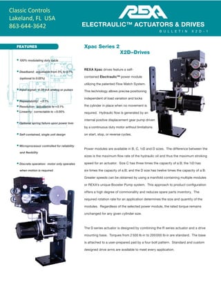
  • 1. FEATURES Xpac Series 2 X2D – Drives REXA Xpac drives feature a self- contained Electraulic™ power module utilizing the patented Flow Match System. This technology allows precise positioning independent of load variation and locks the cylinder in place when no movement is required. Hydraulic flow is generated by an internal positive displacement gear pump driven by a continuous duty motor without limitations on start, stop, or reverse cycles. Power modules are available in B, C, ½D and D sizes. The difference between the sizes is the maximum flow rate of the hydraulic oil and thus the maximum stroking speed for an actuator. Size C has three times the capacity of a B; the ½D has six times the capacity of a B; and the D size has twelve times the capacity of a B. Greater speeds can be obtained by using a manifold containing multiple modules or REXA's unique Booster Pump system. This approach to product configuration offers a high degree of commonality and reduces spare parts inventory. The required rotation rate for an application determines the size and quantity of the modules. Regardless of the selected power module, the rated torque remains unchanged for any given cylinder size. The D series actuator is designed by combining the R series actuator and a drive mounting base. Torques from 2 500 lb·in to 200 000 lb·in are standard. The base is attached to a user-prepared pad by a four bolt pattern. Standard and custom designed drive arms are available to meet every application. • 100% modulating duty cycle • Deadband: adjustable from 5% to 0.1% (optional to 0.05%) • Input signal: 4-20 mA analog or pulses • Repeatability: < 0.1% • Resolution: adjustable to < 0.1% • Linearity: correctable to < 0.05% • Optional spring failure upon power loss • Self-contained, single unit design • Microprocessor controlled for reliability and flexibility • Discrete operation: motor only operates when motion is required ELECTRAULIC™ ACTUATORS & DRIVES B U L L E T I N X 2 D - 1 Classic Controls Lakeland, FL USA 863-644-3642
  • 2. X 2 D – 1 2 Electraulic™ Actuation The word Electraulic™ was coined by REXA to describe our revolutionary technology which combines the simplicity of electric operation, the power of hydraulics, the reliability of solid state electronics and the flexibility of user configured control. A hydraulic system has long been recognized as providing superior performance in the operation of final control elements. Unfortunately, advantages such as quick response, precision and high stiffness were often outweighed by frequent maintenance, nonstandard construction and high cost. By utilizing Electraulic technology, REXA is able to bring to general process control the advantages of hydraulic operation without the conventional drawbacks. Self-contained actuator mounted hydraulics, low maintenance, low power consumption and rugged components are inherent in REXA's proven design. The foundation of Electraulic technology is the Flow Match System, a patented breakthrough in hydraulic circuitry. Motor oil, driven by a continuous duty motor and gear pump, is transferred through the Flow Match Valves (FMV) from one side of a double acting cylinder to the other. Variations in magnitude and direction of the load have no effect upon control. When position is reached the motor shuts off and the FMVs lock the actuator in place. For the complete story, request the publication Theory of Operation. Control Processor The Xpac is operated by a dedicated microprocessor, the position Control Processor (CPU). Contained within the control enclosure, the CPU has three modes of operation: Automatic, Setup and Local. For modulating operation, the CPU is in the Automatic Mode and functions much like a conventional positioner. The control signal and actuator's position (indicated on the enclosure display) are continually compared to each other. If the difference between these values is greater than the selected deadband, then the motor is rotated in the required direction until the new position is reached. Response to a change in control signal is immediate. The CPU is calibrated in the Setup mode by a simple routine which provides the user complete control over actuator operating parameters. Speed, stroke, deadband, acceleration, control signal, and gain can be configured into the CPU by using a three button keypad and the display. This menu-driven Setup eliminates the time consuming and often difficult procedures associated with limit and/or torque switches and potentiometers. Programmed parameters are retained in a permanent memory. For unusual or difficult applications, more sophisticated control capabilities such as flow characterization and water hammer suppression (two speed) are available. To protect saved setup parameters from unwarranted change access to the Setup mode can be restricted by a passcode. Local mode allows stroking of the Xpac from the keypad on the CPU. The display will indicate actuator position. The current control signal and last encountered error can also be shown. 
  • 3. 3 X2D Specifications Xpac Drive European Compliance (OPT) Outputs 2 500 lbf·in  –200 000 lbf·in (282 N·m –22 597 N·m) For higher outputs, contact the factory. Control Signal Analog: 4– 20 mA (STD) Deadband Adjustable from 5% to 0.1% (optional to 0.05%) Failure Mode Fail-in-place (STD); Spring or Accumulator for fail open/closed (OPT) Materials of Construction Anodized aluminum (Electraulic module), anodized aluminum and steel (rack and pinion cylinder) Environmental Rating NEMA 4 (STD); IP66; NEMA 4X (OPT) Electronics Hazardous Location Rating (OPT) CSA approved Cl 1, Div 2, grps A, B, C, & D (OPT) CSA approved Cl 1, Div 1, grps C, & D (OPT)  / ATEX, II 3G EEx nA II T3 -40 °C ≤ Ta ≤ 65 °C / ATEX, II 2G EEx ‘d’ iiB, T3 -40°C ≤ Tamb ≤ 65°C TemperatureRange 1 Actuator Construction Standard High Temp. Type D Drive Cylinder +10 °F to +200 °F -10 °F to +200 °F -76 °F to +200 °F -5 °F to +250 °F (-12 °C to +93 °C) (-23 °C to +93 °C) (-60 °C to +93 °C) (-20 °C to +121 °C) Installation Requirements None 1 inch thermal insulation † Heat tracing & 1 inch thermal insulation † Optional High Temp Construction  Feedback Non-contacting potentiometer Thin film potentiometer (10 x106 cycles) Electronics Temperature Range Separate Control Enclosure with CPU, motor driver, power supply, transient protection and termination. -40 °F to +140 °F (-40 °C to +60 °C) -40 °F to +120 °F (-40 °C to +50 °C) Motor Type Stepper Servo Motor Designation B C ½D D D,P9 D,P40 PowerRequirements 24 Vdc OPT2 OPT2 CF — — — 48 Vdc OPT2 CF CF — — — 115 Vac STD STD STD OPT ² — — 208/230 Vac OPT2 OPT ² OPT2 STD STD * — 240 Vac — — — — — STD ** 480 Vac OPT ² OPT ² OPT ² OPT ² OPT*2 OPT**2 ¹ Note: High ambient temperatures affect oil viscosity which may affect actuator rated output. Consult TM19-2 for complete temperature guidelines. ² Optional power voltage requires separate transformer/inverter † These items are not supplied by REXA. * 3-phase power is required. ** 3-phase power is required; 240 Vac only. REXA is continually improving the design of its products. As such, specifications are subject to change. Check with factory about Accumulators and other options.
  • 4. X 2 D – 1 4 Features CONTROL INTERFACE The standard user interface is a five-button membrane key pad located on the outside of the control enclosure door. A two-line vacuum fluorescent emissive display is visible above the keypad. Once the unit is wired, all calibration and operation functions can be performed without opening the enclosure. For installations where an external keypad is not possible, the display and a five-button control board may be mounted inside the enclosure. POSITION TRANSMITTER This standard feature allows for a two-wire 4-20 mA signal that is proportional to actuator position and selectable for direct or reverse action. The transmitter’s output is optically isolated from the electronics and may be configured as an active or passive device. A passive position transmitter requires an external DC power source while an active device is powered from an internal 24 Vdc power supply. Passive Active Resolution <0.1% of full stroke Maximum External Load 1000 ohms @ 36 Vdc 700 ohms @ 24 Vdc Minimum Supply Voltage 10 + (0.02 x RLOAD ) Vdc 24 Vdc (internal supply)Maximum Supply Voltage 36 + (0.004 x RLOAD ) Vdc RELAYS Standard units are supplied with 4 AC/DC type high capacity photo-MOS relays for output indications. Relays 1 and 2 are used as ‘electronic limit switches’ and may be set in the calibration mode. Relays 3 and 4 provide a warning (3) and/or alarm (4) to indicate possible problems with the equipment. (Load Voltage: 200 Vac/Vdc; Load Current: 1 amp) Relay #1 is used for low position indication. During calibration, it may be set from 0.1 to 99.9, but must be lower than Relay #2. The LED shows status of the relay; when the LED is on, the relay is energized. Relay #2 is used for high position indication and may be set from 0.1 to 99.9, but must be higher than Relay #1. The LED shows status of the relay; when the LED is on, the relay is energized. Alarm is used to indicate when the actuator is unable to follow the control signal as defined. The LED shows the status of the alarm relay; during an alarm event, the LED is turned off. Warning is used when the actuator detects a problem, but is still able to operate as defined. The LED shows the status of the warning relay; during a warning condition, the LED is turned off.
  • 5. 5 Table 1 Standard Damper Arm & Mounting Base Dimensions in Inches (mm) A B C D E F G H J K L M N O P Q R D2 500 / D5 000 13.00 8.00 6.00 4.00 2.50 5.00 3.75 0.56 0.63 0.37 10.0 4.30 3.25 6.75 4.00 0.75 NA (330) (203) (152) (102) (64) (127) (92) (14) (16) (9) (254) (109) (83) (171) (102) (19) D10 000 / D20 000 17.50 12.00 9.00 6.00 3.25 8.00 5.19 0.81 1.00 1.00 10.00 3.30 3.30 15.00 12.19 1.00 NA (445) (305) (229) (152) (83) (203) (132) (21) (25) (25) (254) (84) (84) (381) (310) (25) D50 000 / D100 000 26.00 18.00 13.50 9.00 5.00 12.00 8.75 1.06 1.75 1.50 12.00 6.44 4.80 20.0 16.75 1.50 12.50 (660) (457) (343) (229) (127) (305) (222) (27) (44) (38) (305) (164) (122) (508) (425) (38) (318) FAIL-SAFE OPTION Accumulator Fail positioning utilizes a reservoir and piston-type accumulator placed parallel with the cylinder. While the power module is used to pressurize the accumulator, it is isolated from the main hydraulic circuit during normal operation. Table 2 provides estimated times for failure based on cylinder size and stroke. Table 2 Model Estimated Fail Time* (seconds) D2 500 .30 D5 000 .40 D10 000 .50 D20 000 .75 D100 000 3.0 *For additional information refer to PM21-2.
  • 6. X 2 D – 1 6 MANUAL OVERRIDE OPTIONS When electric power is unavailable, REXA actuators can be operated with one of two manual operators. A Declutchable Handwheel/Drill Drive may be mounted to the back end of the motor. Once engaged, it can be used to turn the motor shaft and hence the pump in either direction. Removing the handwheel from this mechanism reveals a hex drive which allows for the connection of a corded or cordless drill. A Manual Hydraulic Pump may be mounted on the actuator. This unit bypasses the pump and FMV, drawing oil from one side of the cylinder and displacing it to the other. This unit offers significantly faster operating speeds than the handwheel. Manual Override Device Handwheel on Power Module Manual Hand PumpB C D Flow Rate 0.01 in3 /rev 0.03 in3 /rev 0.054 in3 /rev 0.50 in3 /pump Revolutions or Pumps per 1 000 lbf per 90° of rotation 200 65 36 4 DEVICE COMMUNICATIONS The standard control signal for the X2 Series is an analog 4-20 mA signal. Optional control boards are used to provide a choice of control signals; including Pulse, HART Enabled and Foundation fieldbus™ communications. PULSE OPERATING SYSTEMS Originally developed for gearmotor actuators, these systems provide a pulsed low-power signal to define the required position. The system can be adjusted for a variety of pulse durations (time of the pulse) and increments (percent of resulting stroke). For additional information, refer to PM 16-2. HART COMMUNICATION PROTOCOL The HART protocol board uses a frequency shifting key (FSK) modem to impose a digital signal on top of the 4-20 mA analog loop. This allows for continuous control via the analog signal as well as bidirectional digital communications. The HART Protocol Revision 5.0 implemented in the X2 utilizes the Universal Commands as well as a limited number of Common Practice and Device Specific Commands. This implementation eliminates the need for a specific Device Driver (DD). When a field instrument is polled, it will report Universal and Common Practice Commands. These commands include Device Status and the Dynamic Variables. The Dynamic Variables are Position (the Primary Variable) and Cylinder Pressure Differential (optional and requires additional equipment). Foundation Fieldbus™ H1 Integration An option I/O board converts X2 control parameters for Foundation fieldbus communication. The Resource Block provides device identification while Analog Blocks communicate information such as set point, position, and actuator cylinder differential pressure (optional). The device status including operating mode and any error conditions can also be communicated. Partial Stroke Testing (PST) functionality is available through a data collection function. Up to 200 samples of the set point, position and differential pressure (if so equipped), can be collected and stored. The collection rate can be set from 1 to 20 samples per second. Collection can be initiated “manually” via the network or automatically via a definable set point differential.
  • 7. 7 CONTROL PARAMETERS During calibration of the unit, certain parameters that set the operating and control range are required. These are entered through the Calibrate menu in the Setup mode. Additional menus offer several other adjustments that will allow the user to fine tune the operation of the X2 to their specific application. Some of the options are listed below. For additional information on any of these parameters refer to the Installation and Operation Manual. SPEED, ACCELERATION AND GAIN Multiple settings are available that allow the unit to be fine tuned for a specific application. The units gain can be changed to adjust how aggressively it responds to a change in signal. Multiple rates of acceleration (ramping of speed) and speed can be set along with parameters that define when to switch between the options. Different operating speeds can even be set for Manual and Auto operation modes. DEADBAND Deadband is the maximum allowable deviation on a percentage basis, between the defined signal range and defined travel range. This can be set anywhere from 5% to 0.1% (optional to 0.05%). A lower setting generally improves accuracy while a higher setting reduces motor duty cycle, power consumption and seal wear, extending actuator life cycle. BUMPLESS TRANSFER This setting allows the user to define the total time the actuator takes to travel to the current target when switched from Local or Setup to Auto. This function can be helpful in preventing upsets in systems that can not handle rapid flow disturbances. With a range from 10 to 90 (seconds), the default setting is Off. MINIMUM MODULATION This parameter sets the upper limit of an optional no- modulating band at the low (closed) end of travel. Many severe service valves reduce fluid energy through staged pressure reductions. These designs often include a minimum control Cv, below which the pressure reduction occurs between the seat and plug rather than a resistive element. Operation in this range usually results in costly trim damage and plant down time. Min-Mod allows the valve to close or remain closed for any signal below the corresponding minimum Cv and operate normally for signals above the minimum Cv, extending valve life. With a range from 0.1 to 99.9 (percent of calibrated stroke), the default setting is Off. FLOW CHARACTERIZATION The Xpac is designed to have an inherent linear relationship between Control Signal and stroke (i.e.: 10% CS = 10% stroke). The ability to modify this characteristic can assist in loop tuning. Changing the Xpac’s characteristic can have a profound effect on the behavior of the control loop and should only be undertaken with a thorough understanding of the effect. The stroke position can be modified at 10% control signal intervals. The only restriction is that each stroke position must be between and at least 2.5% from the adjacent positions. The default setting is Off. REMOTE MANUAL CONTROL The actuator may be equipped to connect to a remotely located manual station. The basic station includes one Remote/Auto: two-position maintained switch and one Open / Off/ Close: three-position maintained switch. The two- position switch is used to alternate between Auto and Auto- Rman (remote manual) modes. In the Auto-Rman mode, turning the three-position switch to Open or Close will move the actuator in the open or close direction. Returning to center (Off) will stop the actuator at the current position. As an additional option, a seven segment LED digital display board may be connected to the standard position transmitter to display actuator position at the remote manual station. 
  • 8. ELECTRAULIC™ ACTUATORS & DRIVES REXA 4 Manley Street W. Bridgewater, MA 02379 Telephone: 508.584.1199 Fax: 508.584.2525 www.rexa.com The model number provides a physical description of the mechanical portion of the actuator. The output torque, power modules and failure mode are described in this simple system. The rotation rate specifies the maximum speed of operation for a particular actuator and power module combination. Contact your local representative for complete product definitions, cost and availability. How To Order REXA is continually improving the design of its products. As such, specifications are subject to change ISO 9001:2008 Certified Model Number Example: X2D20000-90-D-P A D series Xpac drive with 20000 lb·in of torque and D size power module. Any rotation is adjustable up to 90 degrees. Rotation rate is 8 seconds. Power Modules B: Single B C: Single C ½D: Single ½D 2D: Two D Manifold 2C: Two C Manifold D,P9: Booster Pump D,P40: Booster Pump Drive X2D_ _ _ _ – _ _ – _ – P-_ Torque Rotation (lb·in) (degrees) 2 500 – 90°, 120° 5 000 – 90°, 120° 10 000 – 90°, 120° 20 000 – 90°, 120° 50 000 – 90°, 120° 100 000 – 90°, 120° 200 000 – 90°, 120° 09/2015 Hazardous Area Code C1: CSA-Class 1, Div 1 Actuator Only C2: CSA-Class 1, Div 2 Actuator and Electronics C5: CSA-Class 1, Div 1 Actuator Only, Class 1, Div 2 Electronics Only C6: CSA- Class 1, Div 1 Actuator and Electronics CA: CSA-Class 1, Div 2 Actuator Only Rotation Rate (seconds per 90° rotation) Power Module Torque lb·in (N·m) B C ½D/2C D 2D D,P92 D,P402 SF1 AF3 2500 (282 N·m) 15 5 2.5 1.25 NA NA NA 1.25 <1 5000 (565 N·m) 30 10 5 2.5 1.25 NA NA 2.5 <1 10000 (1 130 N·m) 53.3 18 9 4.5 2.25 1 NA 5 <1 20000 (2 260 N·m) 105 36 18 9 4.5 2 NA 10 <1 50000 (5 650 N·m) NA 92 46 23 11.5 5.1 1.1* NA 1.5 100000 (11 300 N·m) NA NA 92 46 23 10.2 2.3* NA 3 200000 (22 597 N·m) NA NA NA 89 44.5 20 4.5* NA 6 400000 (45 194 N·m) NA NA NA 178 89 39.5 8.9* NA 12 In most installations, these speeds may be reduced by a factor of four without affecting the rated output. 1 SF–Spring Failure. Estimated time is for the standard solenoid and spring. The actual times may vary based on spring force and temperature. Faster times are available. 2 D,P9 and D,P40. Booster pumps provide high speed operation, while maintaining fine positioning capability. Rotation rates shown are for 95% of total travel. 3 AF–Accumulator Fail. Refer to PM21-2. *Rotation rates shown assume 240 V motor power. Operating at 208 V limits actuator speed to 80% of stated values.