Presentation: Power & Eenrgy for Unmanned Undersea Vehicles (UUVs)
•
2 gefällt mir•553 views

UUV and UDNS Energy & Power Technology Challenges Energy and power density plus: • Air-independent operation • Refuelability • Multi-mission capability • Stealth • Safety • Environmentally benign • Endurance (high energy density) • Weight/volume constraints • Buoyancy • Quick start-up • Low/no signature • Cost effective Power and energy_sources_10-27-11

Empfohlen
Weitere ähnliche Inhalte
Was ist angesagt?
Was ist angesagt? (20)
Ähnlich wie Presentation: Power & Eenrgy for Unmanned Undersea Vehicles (UUVs)
Ähnlich wie Presentation: Power & Eenrgy for Unmanned Undersea Vehicles (UUVs) (20)
Mehr von chrisrobschu
Mehr von chrisrobschu (20)
Kürzlich hochgeladen
Kürzlich hochgeladen (20)
Presentation: Power & Eenrgy for Unmanned Undersea Vehicles (UUVs)
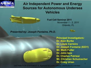
- 1. Air Independent Power and Energy Sources for Autonomous Undersea Vehicles Presented by: Joseph Fontaine, Ph.D. Fuel Cell Seminar 2011 November 1 - 3, 2011 Orlando, FL Principal Investigators: Dr. Alan Burke Dr. Louis Carreiro Dr. Joseph Fontaine (8231) Mr. Mark Fuller Dr. John Izzo Dr. Charles Patrissi Mr. Christian Schumacher Dr. Craig Urian 1 DISTRIBUTION STATEMENT A. Approved for public release; distribution is unlimited
- 2. Autonomous Undersea Vehicle (AUV) • A self-propelled submersible whose operation is either fully autonomous or under minimal supervisory control without tether except for possible data linking • Military AUVs typically operate submerged and independent for periods of time ranging from tens to hundreds of hours. 2 DISTRIBUTION STATEMENT A. Approved for public release; distribution is unlimited
- 3. AUV diversity of size 3 DISTRIBUTION STATEMENT A. Approved for public release; distribution is unlimited
- 4. 2004 UUV Master Plan • Intelligence, Surveillance, Reconnaissance • Mine Countermeasures • Anti-Submarine Warfare • Inspection / Identification • Oceanography • Communication / Navigation Network Node • Payload Delivery • Information Operations • Time Critical Strike 4 www.navy.mil/navydata/technology/uuvmp.pdf DISTRIBUTION STATEMENT A. Approved for public release; distribution is unlimited
- 5. Unique and Innovative Solutions Required to Successfully Address ALL of the Air- Independent Energy & Power Challenges UUV and UDNS Energy & Power Technology Challenges • Air-independent operation • Refuelability • Multi-mission capability • Stealth • Safety • Environmentally benign • Endurance (high energy density) • Weight/volume constraints • Buoyancy • Quick start-up • Low/no signature • Cost effective 5 Energy and power density plus: DISTRIBUTION STATEMENT A. Approved for public release; distribution is unlimited
- 6. * David Linden Handbook of Batteries, 2nd ed, 1995 Specific energy, Wh/kg Air Independent energy is not a high priority for industry. NUWCDIVNPT efforts focused on faster delivery to the fleet. Air Independent Navy Power and Energy Needs vs. COTS Battery Solutions 1375 Wh/kg = TNT DNS Requirements? Specificpower,W/kg 6 DISTRIBUTION STATEMENT A. Approved for public release; distribution is unlimited
- 7. Fuel Cell Overview: Fuel / Oxidizers Fuel • Hydrogen – compressed gas – cryogenic liquid • Not safe • Low energy density • Hydrocarbons – light (C1 - C4) – Methanol (unsafe) – liquid (JP-8, diesel) • High energy density • Relatively safe • Hydrogen-containing compounds – LiAlH4 – NaBH4 • Generation of hydrogen • Direct reaction Oxidizer • Oxygen – compressed gas – cryogenic liquid • Hydrogen peroxide (H2O2) 7 DISTRIBUTION STATEMENT A. Approved for public release; distribution is unlimited
- 8. UUV & UDNS Energy Challenges and Solutions • Main challenges for UUV application: – Fuel & Oxygen Storage Density (liquids preferred) – Stack reliability for multiple thermal/Electrochem cycles & 1000’s of hours operation – Minimal startup requirements • Fuel Cell technology has the potential to greatly increase UUV mission time compared with current battery technology. Borohydride storage Hydrogen peroxide storage Liquid Oxygen Storage (LOX) SOFC Stack Diesel Fuel Storage Anode Recycle Pump Fuel Processor and CO2 scrubber Liquid Oxygen Storage (LOX) SOFC Stack Diesel Fuel Storage Anode Recycle Pump Fuel Processor and CO2 scrubber 8 DISTRIBUTION STATEMENT A. Approved for public release; distribution is unlimited
- 9. 9 US Government Only NUWC Code 823 Applied Engineering Mechanics Code 823 Dr. Jason Gomez Applied Engineering Mechanics Code 8231 Dr. Joseph Fontaine Propulsion and Energy Code 8232 Stanley Polhemus Solid Mechanics and Design Code 8233 Dr. David Beal Vehicle Dynamics and Signature Control Division Charter Provide World Class Technology Solutions in the areas of; Simulation Based Design, Technology Integration, Structural Design & Analysis, Structural Acoustics, Energy and Propulsion, Dynamic Structural & Shock Response Analysis, Systems Engineering & Prototyping and Undersea Vehicle Guidance, Control and Hydrodynamics DISTRIBUTION STATEMENT A. Approved for public release; distribution is unlimited
- 10. 10 US Government Only 8231 Current and Recent Roles • Technology Developer – Identification and investigation of novel technologies for advanced Navy power sources • System Integrator – Initial technology investigation through prototype development • System analysis and evaluation – Development of NUWC concepts and analysis of concepts developed by others in support of ONR and NAVSEA sponsors • Technical Oversight – Primarily technical assistance on SBIR funded topics DISTRIBUTION STATEMENT A. Approved for public release; distribution is unlimited
- 11. Participation In Government Sponsored Energy R&D Programs • Technical guidance to a variety of organizations in support of DARPA, ONR, DOE, Army, and NAVSEA • NUWC Participation – Integrated Product Team (IPT) • Rules governing placement of energy sources on Navy platforms – Interagency Power Group (IAPG) (Federal Organization) – Lithium Battery Technical and Safety Group – Power Sources Conferences (Session chair / presentations) – Fuel Cell Working Group 11 Maintain breadth and depth of knowledge in an effort to meet / advise Navy’s needs for power and energy – honest broker. DISTRIBUTION STATEMENT A. Approved for public release; distribution is unlimited
- 12. 12 US Government Only Fuel Cells for Undersea Vehicles 30-Cell SOFC Stack from Delphi Corp. Attributes: Liquid Hydrocarbon capable High efficiency, demonstrated >50% @ 1kw power High Temperature system Required startup sequence Thermal management Industry developing air based system Solid Oxide Fuel Cell (SOFC) Attributes: Pure hydrogen fuel source High efficiency, > 50% Low Temperature system Simple/fast startup Minimal balance of plant Industry developing air based system NASA developed / demonstrated specialized air-independent variant 1000 s of hours Proton Exchange Membrane (PEM) DISTRIBUTION STATEMENT A. Approved for public release; distribution is unlimited
- 13. SOFC System Technical Challenges DISTRIBUTION STATEMENT A. Approved for public release; distribution is unlimited
- 14. Solid Oxide Fuel Cell Power System for Undersea Vehicles Louis G. Carreiro, A. Alan Burke 30-Cell SOFC Stack from Delphi Corp. Approach • Evaluate SECA-sponsored/developed stacks under UUV operating conditions of pure oxygen and diesel reformate reactants as part of a DoE collaboration. • Coordinate with SBIR programs to test balance of plant components (i.e. sorbent, reformer, high-temperature blower) • Maintain test stand for 1-3 kW fuel cell system testing • Perform modeling at the system level and adapt it to experimental results in order to determine the best way to package hot zone components in an actual 21” UUV energy section S&T Objectives • Operate a SOFC system at a laboratory scale utilizing liquid fuel and pure oxygen. • Quantify via experimentation the technical, operational and logistics issues to facilitate the realization of an affordable and high-energy UUV system with greater than 300 Wh/kg. • Generate, based on above results, an integrated system design concept for a 21” UUV platform for consideration as a transition package. Power: 1.5 kW Volume: 2.5 L Mass: 9 kg Accomplishments / Impact / Readiness • Demonstration of 30-Cell Delphi Stack integrated with InnovaTek Steam Reformer, R&D Dynamics High-Temperature Blower and TDA Research CO2 Sorbent Bed • Benchmarks achieved in this “first of its kind” demonstration: > 75% S-8 Utilization, > 90% Oxygen Utilization, > 50% Efficiency (PSOFC / S-8 LHV), and > 1 kW Power • Future work will focus on long-duration system level tests, thermal cycling, platform integration (removal of furnaces) and defining methods for start-up and sorbent regeneration DISTRIBUTION STATEMENT A. Approved for public release; distribution is unlimited
- 15. Goal: Show that Waste Heat from SOFC stack can be used to drive steam reformer (from Delphi Corporation) This task could not be accomplished without also using a burner to partially drive (heat) the reformer Steam Reformer SOFC Stack Burner DISTRIBUTION STATEMENT A. Approved for public release; distribution is unlimited
- 16. Delphi SOFC Stack Steam Generator Delphi Steam Reformer CO2 gas (0-5 SLPM) Anode Exhaust N2 gas (0-20 SLPM) H2O steam Cathode exhaust O2 gas (0-10 SLPM, 2 channels) Reformate (to condenser andGC for analysis) H2 gas (0-20 SLPM, switchover) Combustor CH4 gas for burner (0-5 SLPM) Compressor AirSupply Combustor Exhaust LiquidFuel OR CH4 gas (0-5 SLPM) DISTRIBUTION STATEMENT A. Approved for public release; distribution is unlimited
- 17. Delphi Reformer Steam Generator Condenser CH4 gas (0-4 SLPM) ReformateN2 gas (optional) (0-20 SLPM) H2O steam Combustor exhaust Anodeexhaust (to GC) Air from Compressor Combustor LiquidFuel DISTRIBUTION STATEMENT A. Approved for public release; distribution is unlimited
- 18. HC slippage when Ref outlet T < 500° C ◦ Ethane, ethylene… Ref efficiency did not include superheated steam Combustor temperature used to verify proper reformer temperature / active catalyst Mass balance solved to check for possible coking or gas leakage DISTRIBUTION STATEMENT A. Approved for public release; distribution is unlimited
- 19. Delphi SOFC Stack Anode Recycle Blower Delphi Steam Reformer Anode Outlet N2 gas (0-20 SLPM) Cathode exhaust O2 gas (0-10 SLPM, 2 channels) Reformate Exhaust (to condenser and GC for analysis) CH4 or H2 gas (0-20 SLPM) Combustor H2 or CH4 gas (0-10 SLPM) Compressor Air Supply Combustor Exhaust CO2 Scrubber AnodeInlet Recycled Reformate Steam Trap / Condenser System Level Demonstrations with only methane gas and pure oxygen reactant feeds DISTRIBUTION STATEMENT A. Approved for public release; distribution is unlimited
- 20. PEMFC System Technical Challenges DISTRIBUTION STATEMENT A. Approved for public release; distribution is unlimited
- 21. Initial PEMFC System Design Notional 21” diameter, 52” long UUV energy section. 17” energy conversion mid section consisting of 2kW PEMFC, decomposition reactor beds, batteries, 2” cable pass through conduit. 4 bulkheads used to isolate reactant storage bladders. DISTRIBUTION STATEMENT A. Approved for public release; distribution is unlimited
- 22. Technical Challenges • Borohydride H2 Subsystem (NaBH4 + 2H2O NaBO2 + 4H2 + heat) – Maximizing storage concentration (liquid vs. dry powder) while retaining re-fuelability – Water management of H2 gas feed to stack – Reactor longevity due to borate precipitation – Ability to drain reaction product • Peroxide O2 Subsystem (2H2O2 2H2O + O2 + heat) – Reactor longevity – Water management of O2 gas feed to stack • Fuel Cell Subsystem (2H2 + O2 2H2O) – Identification of manufacturer of O2/H2 PEMFC stacks – Appropriate stack format to meet 100V specifications (i.e. active area size) – Water Management Strategy DISTRIBUTION STATEMENT A. Approved for public release; distribution is unlimited
- 23. Fuel Cell Subsystem: Water Management • Recirculation Blowers: Promote excess gas flow through fuel cell to remove product water – BoP penalty and reliability • Size, weight and power – Identified Parker Hannifin UniVane™ Compressors • No longer available due to weak Market demand • Reliability – Other COTs pumps can not meet temperature (60-80 oC), high humidity, flow rate, operating pressure (gas tight seals), boost pressure (result of pressure drop through stack and system) and/or reactant demands. – Custom blower option >$200k – Gas water separator unit required=> development effort/system integration effort Blowers are not seen as a viable technology path DISTRIBUTION STATEMENT A. Approved for public release; distribution is unlimited
- 24. Fuel Cell Subsystem: Water Management => NASA Collaboration • Two alternative approaches to blowers for product water removal Glenn Research Center anode cathode H2O MEA H2O H2 O2 H2O H2O coolant hydrophilicmembrane anode cathode H2O MEA H2O H2 O2 H2O H2O coolant hydrophilicmembrane Ejector Passive Water Removal ∆P across porous membrane removes product water Alternative to blowers to facilitate gas recirculation in flow threw fuel cells for product water removal Johnson Space Center DISTRIBUTION STATEMENT A. Approved for public release; distribution is unlimited
- 25. Points of Contact: NASA: Mark Hoberecht (mark.a.hoberecht@nasa.gov, 216-433-5362) Infinity Fuel Cell: Bill Smith (wsmith@infinityfuel.com, 860-688-6500) NAVSEA: Joseph Fontaine (Joseph.Fontaine@navy.mil, 401-832-2887) Non-Flow Through Fuel Cell Stack (Developed by Infinity Fuel Cell and Hydrogen) Balance of Plant (Developed by NASA Glenn) Balance of Plant (Developed by NASA Glenn) H2 Vent S S P P S H2O In O2 Vent O2 Supply H2O Drain H2 Supply S S Oxygen/Water Pressure Control H2 Supply Solen. Valve H2 Vent Solen. Valve O2 Supply Solen. Valve O2 Vent Solen. Valve O2 Pres. Xducer H2 Pres. XducerP P O2 Pres. Xducer H2 Pres. Xducer O2 Pressure Regulation H2 Pressure Regulation P H2O Pres. Xducer Coolant In Coolant Out H2O Drain Solen. Valve H H e- H+ e- H H H+ H+ H+ O- O- O O H H O H H O e- e- H H H H O O H H O H H O H H O H H O H H O H H O H H O H H O H H O H H O H H O To Drain Hydrogen Cavity PEM Membrane Oxygen Cavity Liquid/Gas Separator Water Cavity IndividualFuelCell L o a d DISTRIBUTION STATEMENT A. Approved for public release; distribution is unlimited
- 26. Infinity Fuel Cell 26 DRATS Crater Stack No. 1 On Test Have demonstrated >1300 hrs continuous operation with 50cm2 4 cell stack DISTRIBUTION STATEMENT A. Approved for public release; distribution is unlimited
- 27. Subsystem: Hydrogen Peroxide • Conducted historical review of peroxide usage in torpedo propulsion and literature review • Developed model for the decomposition reactor bed – Research indicated preference for wire mesh reactor compared to other packed bed configurations • Model developed for both prior channeled bus bar and the wired mesh packed bed reactors – Model included both decomposition and thermal management aspects • Decomposition temperature vs. pressure • Heat Exchanger sizing DISTRIBUTION STATEMENT A. Approved for public release; distribution is unlimited
- 28. Subsystem: Hydrogen Peroxide • Evaluated different subsystem designs and integration approaches – Focused on water management to the fuel cell to avoid flooding issues – Compact thermal management • Selected 59% H2O2 – DOT regulations regarding shipping in non specialized drums – Still enough water to minimize thermal runaway situation DISTRIBUTION STATEMENT A. Approved for public release; distribution is unlimited
- 29. Reactor/ Catalyst Comparison DISTRIBUTION STATEMENT A. Approved for public release; distribution is unlimited
- 30. Conclusion • Energy storage is the limiting factor for these next generation systems – New technology development must be tempered by: • Safety (personnel and platform) • Reliability / Robustness • Long shelf life • Pressure tolerance • Total ownership cost 30 Versa Power Systems Hotel Battery Board Hotel Batteries Velocity Sensor Ethernet Hub Motor Controller Board Aft Propulsion Battery Plate DISTRIBUTION STATEMENT A. Approved for public release; distribution is unlimited
- 31. ARL NUWC’s S&T Energy Sponsors, Partners & Collaborators PMS 394 Advanced Undersea Systems Program Office Fuel Cell WG 31 DISTRIBUTION STATEMENT A. Approved for public release; distribution is unlimited