2. This chapter’s focus is the strategies for scaling WANs with
Cisco routers. The packet switching protocols covered in this chapter include
Frame Relay, X.25, SMDS, and ATM.
We will cover the basic WAN connection considerations and talk about
the different Cisco connection services. We’ll then cover the details of con-
figuring and monitoring the Cisco packet switched networks.
The CCNP test objectives covered in this chapter are as follows:
s Compare the differences between WAN connection types: dedicated,
asynchronous dial-in, dial-on-demand, and packet switched services
s List at least four common issues to be considered when evaluating
WAN services
WAN Scalability
LANs are defined as a network that is restricted to a floor or building.
LAN users often rely on asynchronous connections to access the remote ser-
vices available outside the confines of their local LAN.
However, as organizations evolve and expand, they’re often faced with
the need to make their networks efficiently support WAN services to the
Internet and remote divisions at LAN-type speeds. Achieving that is simply
beyond the capabilities of asynchronous connections.
Because it just isn’t always feasible for an organization to create its very own
private, dedicated WAN connection, alternative approaches to forging connec-
tions across public networks have been sought and expansively developed.
3. WAN Scalability 405
Connection Considerations
When a company grows, it’s imperative that its internetwork grows with it.
The network’s administrator must not only understand the various user-
group differences regarding their specialized needs for the mélange of LAN
and WAN resources, they must find a way to meet—or better yet—exceed
these requirements, while planning for growth as well. Below, we’ve listed
important factors to consider when defining and researching business
requirements for the purposes of internetwork design or refinement.
Availability Because networks are so heavily relied upon—they’re ideally
up and running 24 hours a day, 365 days a year—failures and downtime
must be minimized. It’s also vital that when a failure does occur, it’s easy
to isolate so that the time needed to troubleshoot the problem is reduced.
Bandwidth Accurately determining the actual and eventual bandwidth
requirements with information gathered from both users and manage-
ment is crucial. It can be advantageous to contract with a service provider
to establish connectivity between remote sites. Bandwidth considerations
are also an important element for the next consideration—cost.
Cost In a perfect world, we could just install nothing but Cisco Catalyst
5000 series switches that provide switched 100Mbps to each desktop
with gigabit speeds between data closets and remote offices. However,
since the world’s not perfect, and often budget constraints simply won’t
allow for doing that, Cisco offers an abundance of switches and routers
tailored to many wallet sizes. This is one very big reason why it’s so
important to accurately assess actual needs. A budget must be carefully
delimited when designing an internetwork.
Ease of management The ramifications such as the degree of difficulty
associated with creating any network connections must be understood
and regarded carefully. Factors associated with configuration manage-
ment include analyses of both the initial configuration and the ongoing
configuration tasks related to running and maintaining the entire inter-
network. Traffic management issues—the ability to adjust to different
traffic rates, especially in bursty networks—also apply here.
Type of application traffic This can be typically comprised of small to
very large packets, and the internetwork design must reflect and regard
the typical traffic type to meet business requirements.
4. Chapter 11 s WAN Scalability406
Routing protocols The characteristics of these protocols can cause some
ugly problems and steal a lot of precious bandwidth in networks where
they’re either not understood or not configured properly.
Cisco Connection Services
Cisco supports many different types of services, providing ample flexibility
and many options for meeting internetworking business requirements. These
services include:
s Dedicated leased lines
s Dial-in modems
s Dial-up connections using Cisco routers (DDR)
s Packet switched services
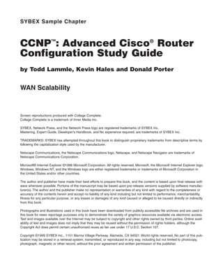
Dedicated
Point-to-point serial links are dedicated links that provide full-time connec-
tivity. Cisco router serial ports are used to gain access at a rate of up to
45Mbps. They connect into a channel service unit/data service unit (CSU/
DSU), which then plugs into the demarc provided by the telephone company.
Figure 11.1 shows how point-to-point connections can be made between
remote offices and the corporate office.
If the established business requirements dictate that constant connection
and steady data flow must prevail, a dedicated point-to-point connection can
be an optimal solution—but even so, this approach does have a disadvantage
associated with it. Point-to-point connections require paying tariffs for them
even when the connection is in an idle state with no data being transmitted.
F I G U R E 11.1
Point-to-point
connections between
branches and the
corporate office
5. WAN Scalability 407
Asynchronous Dial-In
Any user with an asynchronous modem can make connections to an inter-
network using the public switched telephone network (PSTN), and there are
many common situations requiring this type of access. Users who are trav-
eling can dial in to gather e-mails or update a database, while others may
want to dial in from home to finish projects, send and retrieve e-mails, and
even print documents to be available for them when they arrive at work the
next day.
Cisco answers this need by providing a variety of asynchronous dial-in
products such as the AS5200 access server. This device provides up to 48
asynchronous modems for both dial-in and dial-out services, and it runs the
Cisco IOS, so it can also perform routing, authentication, and security-
related tasks. If demands don’t dictate the need for that many ports, there are
Cisco products that offer a lower port density.
Dial-on-Demand Routing
DDR (dial-on-demand routing) allows wide area links to be used selectively.
With it, the administrator can define “interesting” traffic on the router, and
initiate WAN links based upon that traffic. Access lists define interesting
traffic, so there’s a great deal of flexibility given to the administrator. For
instance, an expensive ISDN connection to the Internet could be initiated to
retrieve e-mail, but not for a WWW request. DDR is an effective tool in sit-
uations where WAN access is charged in some time interval, and it’s best to
use it in situations where WAN access is infrequent.
Dial-on-demand routing provides the missing software ingredient for cre-
ating a fully functional backup system. Versatile DDR can be used over sev-
eral different types of connections, and is supported in Cisco IOS version 9
and later. It supports the following networking protocols: IP, IPX, Apple-
Talk, and others. DDR’s flexibility reaches even further. It can be used over
several different types of interfaces—synchronous and asynchronous serial
interfaces, as well as ISDN.
Packet Switched Services
Packet switched services are usually run over a publicly maintained network,
such as the public switched telephone network, but if necessary, a large orga-
nization can build a private packet switched network (PSN).
PSN data delivery can take place within frames, packets, or cells, and
occurs transparently to end users.
6. Chapter 11 s WAN Scalability408
Frame Relay, X.25, SMDS, and ATM are some of the topologies that
employ packet switching technology—they’ll be discussed next.
Packet Switched Networks
As we said, PSNs can be either private or public networks. Switching
devices forward packets using an internal addressing scheme, which can be
entirely different from what’s used on the LAN. This is because a switch
that’s located at the WAN provider’s office will typically check the address
field of the packets only, and then carry out the forwarding based upon the
static routes configured by an administrator.
An administrator must understand how switching protocols operate to
customize the internetwork according to the specific characteristics of the
switched network. For example, Frame Relay will perform a CRC only at the
Data Link layer of the frame, so if the application you need to run on the
WAN doesn’t support upper-layer error checking, Frame Relay may not be
the best solution for you. Because X.25 supports more extensive error
checking, that would be a better choice.
The most popular switching protocols are as follows:
s Frame Relay
s X.25
s SMDS/ATM
Frame Relay
Recently, the high-performance WAN encapsulation method known as
Frame Relay has become one of the most popular technologies in use. It
operates at the Physical and Data Link layers of the OSI reference model, and
was originally designed for use across Integrated Services Digital Network
(ISDN) interfaces. But today, Frame Relay is used over a variety of other net-
work interfaces.
Cisco Frame Relay supports the following protocols:
s IP
s DECnet
7. Packet Switched Networks 409
s AppleTalk
s Xerox Network Service (XNS)
s Novell IPX
s Connectionless Network Service (CLNS)
s International Organization for Standards (ISO)
s Banyan Vines
s Transparent bridging
Frame Relay provides a communications interface between DTE (data
terminal equipment) and DCE (data circuit-terminating equipment—such as
packet switches) devices. DTE consists of terminals, PCs, routers, and
bridges—customer-owned end node and internetworking devices. DCE con-
sists of carrier-owned internetworking devices.
Popular opinion maintains that Frame Relay is more efficient and faster
than X.25 because it assumes error checking will be done through higher-
layer protocols and application services.
Frame Relay provides connection-oriented, Data Link layer communica-
tion via virtual circuits just as X.25 does. These virtual circuits are logical
connections created between two DTEs across a packet switched network,
which is identified by a DLCI. (We’ll get to DLCIs in a bit.) Also, like X.25,
Frame Relay uses both PVCs and SVCs, although most Frame Relay net-
works use PVCs.
Frame Relay with Cisco Routers
When configuring Frame Relay on Cisco routers, you need to specify it as an
encapsulation on serial interfaces. There are only two encapsulation types:
Cisco and IETF (Internet engineering task force). The following router
output shows the two different encapsulation methods when choosing
Frame Relay on your Cisco router:
RouterA(config)#int s0
RouterA(config-if)#encapsulation frame-relay ?
ietf Use RFC1490 encapsulation
<cr>
8. Chapter 11 s WAN Scalability410
The default encapsulation is Cisco unless you manually type in IETF, and
Cisco is the type used when connecting two Cisco devices. You’d opt for the
IETF-type encapsulation if you needed to connect a Cisco device to a non-
Cisco device with Frame Relay. So before choosing an encapsulation type,
check with your ISP and find out which one they use. (If they don’t know,
hook up with a different ISP!)
Data Link Connection Identifiers
Frame Relay virtual circuits are identified by data link connection identifiers
(DLCIs). A Frame Relay service provider, such as the telephone company,
typically assigns DLCI values, which are used by Frame Relay to distinguish
between different virtual circuits on the network. Since many virtual circuits
can be terminated on one multipoint Frame Relay interface, many DLCIs are
often affiliated with it.
For the IP devices at each end of a virtual circuit to communicate, their
IP addresses need to be mapped to DLCIs. This mapping can function as a
multipoint device—one that can identify to the Frame Relay network the
appropriate destination virtual circuit for each packet that is sent over the
single physical interface.
Frame Relay uses DLCIs the same way that X.25 uses X.121 addresses,
and every DLCI number can be given either global or local meaning every-
where within the Frame Relay network. However, the customary implemen-
tation is to give each DLCI local meaning. What does this do? It makes two
DTE devices connected via a virtual circuit use different DLCI values when
referring to the same connection.
Configuring a DLCI number to be applied to an interface is shown below:
RouterA(config-if)#frame-relay interface-dlci ?
<16-1007> Define a DLCI as part of the current
subinterface
RouterA(config-if)#frame-relay interface-dlci 16
Prioritizing DLCI Traffic To control which path traffic will take through a
Frame Relay cloud, you can configure virtual circuits that match parameters
within a priority queue list. These queues can then be matched to a specific
DLCI, providing a traffic management tool to minimize congestion prob-
lems with slower links. This can be really helpful if your network commonly
sustains traffic from sources with high-speed access that’s queued at desti-
nation sites with lower-speed access, and can be achieved by applying pri-
ority levels to the DLCI.
9. Packet Switched Networks 411
The steps to configure DLCI priority levels are as follows:
1. Define a global priority list.
2. Enable Frame Relay on the serial interface.
3. Define either inverse ARP or static mappings.
4. Configure the LMI.
DLCI priority levels provide a way to define multiple DLCIs and associate
each with different types of traffic. However, don’t confuse DLCI priorities
with router priority queues.
G
H You can enable queuing and then use the same DLCIs for queuing by
placing the higher-priority DLCIs into the high-priority queues.
To assign protocol traffic to match the specified parameters of a priority
queue, you use the priority-list protocol command:
Router(config)#priority-list ?
<1-16> Priority list number
Router(config)#priority-list 1 ?
default Set priority queue for unspecified datagrams
interface Establish priorities for packets from a named
interface
protocol Priority queueing by protocol
queue-limit Set queue limits for priority queues
Router(config)#priority-list 1 protocol ?
aarp AppleTalk ARP
appletalk AppleTalk
arp IP ARP
bridge Bridging
bstun Block Serial Tunnel
cdp Cisco Discovery Protocol
compressedtcp Compressed TCP
decnet DECnet
decnet_node DECnet Node
decnet_router-l1 DECnet Router L1
10. Chapter 11 s WAN Scalability412
decnet_router-l2 DECnet Router L2
decnet_router-l2 DECnet Router L2
ip IP
ipx Novell IPX
llc2 llc2
pad PAD links
rsrb Remote Source-Route Bridging
snapshot Snapshot routing support
stun Serial Tunnel
Router(config)#priority-list 1 protocol ip ?
high
medium
normal
low
Router(config)#priority-list 1 protocol ip high ?
fragments Prioritize fragmented IP packets
gt Prioritize packets greater than a specified
size
list To specify an access list
lt Prioritize packets less than a specified size
tcp Prioritize TCP packets 'to' or 'from' the
specified port
udp Prioritize UDP packets 'to' or 'from' the
specified port
<cr>
Router(config)#priority-list 1 protocol ip high gt ?
<0-65535> Packet size (include MAC encapsulation bytes)
The list below provides an explanation of the router output listed above.
s The priority list number represents the number of the priority list—a
value between 1 and 16.
s The protocol name represents the name of the protocol being
specified.
s The priority level represents the name of the queue—high, medium,
normal, or low.
11. Packet Switched Networks 413
s The equality (gt) represents the conditional value.
s The byte count represents the number of bytes within the packet,
including the frame header.
To establish the DLCIs for use by each of the four individual priority
queues that apply the specified priority list to an interface, you use the frame
relay priority-dlci-group command:
Router(config-if)#frame priority-dlci-group ?
<1-16> Assign priority group
Router(config-if)#frame priority-dlci-group 1 ?
<16-1007> DLCI for high priority
Router(config-if)#frame priority-dlci-group 1 16 ?
<16-1007> DLCI for medium priority
<cr>
Router(config-if)#frame priority-dlci-group 1 16 17 ?
<16-1007> DLCI for normal priority
<cr>
Router(config-if)#frame priority-dlci-group 1 16 17 18 ?
<16-1007> DLCI for low priority
<cr>
The list below explains the meaning of the router output above.
s The priority group number represents the number of the priority that’s
applied to the interface, between 1 and 16.
s The high DLCI represents the DLCI number that’s assigned to the high
queue.
s The medium DLCI represents the DLCI number that’s assigned to the
medium queue.
s The normal DLCI represents the DLCI number that’s assigned to the
normal queue.
s The low DLCI represents the DLCI number that’s assigned to the low
queue.
If a DLCI value isn’t configured for a queue, the last assigned DLCI value
used will be propagated to complete the syntax by default.
12. Chapter 11 s WAN Scalability414
Setting Access Lists with Priorities If you want to define an access list
to use a high-priority queue, use the list parameter as shown in the fol-
lowing example:
Router(config)#priority-list 1 protocol ip high ?
fragments Prioritize fragmented IP packets
gt Prioritize packets greater than a specified
size
list To specify an access list
lt Prioritize packets less than a specified size
tcp Prioritize TCP packets 'to' or 'from' the
specified port
udp Prioritize UDP packets 'to' or 'from' the
specified port
<cr>
Router(config)#priority-list 1 protocol ip high list ?
<1-199> IP access list
Router(config)#priority-list 1 protocol ip high list 10 ?
<cr>
You can choose any access list between 1 and 199, which covers IP stan-
dard and IP extended access lists.
Local Management Interface (LMI)
The LMI (Local Management Interface) was developed in 1990 by Cisco
Systems, StrataCom, Northern Telecom, and Digital Equipment Corpora-
tion, and became known as the Gang-of-Four LMI or Cisco LMI. This gang
took the basic Frame Relay protocol from the CCIT and added extensions
onto the protocol features that allow internetworking devices to communi-
cate easily with a Frame Relay network.
LMI messages provide information about the current DLCI values,
whether their significance is global or local, and they report the status of vir-
tual circuits.
G
H Beginning with IOS version 11.2, the LMI type is autosensed. This enables
the interface to determine the LMI type supported by the switch.
13. Packet Switched Networks 415
To configure the LMI type, you need to do as follows:
s Set the LMI type.
s Set the LMI keepalive interval.
s Set the LMI polling and timer intervals (not required).
If you’re not going to use the autosense feature, you’ll need to check with
your Frame Relay provider to find out which type to use instead. The default
type is Cisco, but you may need to change to ANSI or Q.933A. The three dif-
ferent LMI types are depicted in the router output below.
RouterA(config-if)#frame-relay lmi-type ?
cisco
ansi
q933a
As seen in the output, all three standard LMI signaling formats are supported:
Cisco LMI defined by the gang of four (default)
ANSI Annex D defined by ANSI standard T1.617
ITU-T (q933a) Annex A defined by Q.933
To establish the interval at which your router will send keepalive mes-
sages, use the frame-relay keepalive command. The default period is
every 10 seconds, but be aware that this value must be set to less than that
of the corresponding interval on the switch.
Router(config-if)#keepalive ?
<0-32767> Keepalive period (default 10 seconds)
<cr>
The 10-second default interval can also be seen by using the sh int
command:
Router#sh int s0
Serial0 is administratively down, line protocol is down
Hardware is HD64570
MTU 1500 bytes, BW 1544 Kbit, DLY 20000 usec, rely
255/255, load 1/255
Encapsulation FRAME-RELAY, loopback not set, keepalive set
(10 sec)
14. Chapter 11 s WAN Scalability416
LMI enq sent 0, LMI stat recvd 0, LMI upd recvd 0, DTE
LMI down
LMI enq recvd 0, LMI stat sent 0, LMI upd sent 0
LMI DLCI 1023 LMI type is CISCO frame relay DTE
G
H The above output was edited for brevity.
You can set the LMI polling and timer intervals by using the frame-
relay lmi-n39x command. This specifies the interval between full status
requests made to the Frame Relay switch from your router.
Router(config-if)#frame-relay lmi?
lmi-n391dte lmi-n392dce lmi-n392dte lmi-n393dce lmi-n393dte
lmi-t392dce lmi-type
The list below describes the different LMI polling and timer commands.
s The lmi-n391dte sets a full status polling interval on a DTE interface
or NNI (Network-to-Network Interface).
s The lmi-n392dce sets the DCE and NNI error threshold.
s The lmi-n392dte sets the DTE and NNI error threshold.
s The lmi-n393dce sets the DCE and NNI monitored events count.
s The lmi-n393dte sets the DTE and NNI monitored events count.
s The lmi-t392dce sets the polling verification timer on a DCE inter-
face or NNI.
Subinterfaces
You can have multiple virtual circuits on a single serial interface and yet treat
each as a separate interface. These are known as subinterfaces. Think of a
subinterface as a hardware interface defined by the IOS software.
An advantage gained through using subinterfaces is the ability to assign
different network layer characteristics to each subinterface and virtual cir-
cuit, such as IP routing on one virtual circuit and IPX on another. Figure 11.2
shows how a single physical interface simulates multiple logical interfaces.
15. Packet Switched Networks 417
You define subinterfaces with the int s0.subinterface number com-
mand as shown below.
RouterA(config)#int s0.?
<0-4294967295> Serial interface number
RouterA(config)#int s0.16 ?
multipoint Treat as a multipoint link
point-to-point Treat as a point-to-point link
You can define a limitless number of subinterfaces on a given physical
interface (keeping router memory in mind). In the above example, we chose
to use subinterface 16 because that represents the DLCI number assigned to
that interface. However, you can choose any number between 0 and
4,292,967,295.
There are two types of subinterfaces:
Point-to-point Used when a single virtual circuit connects one router to
another
Multipoint Used when the router is the center of a star of virtual circuits
An example of a production router running multiple subinterfaces is
shown below, and corresponds to Figure 11.3. Notice that the subinterface
number matches the DLCI number. Also notice that there is no LMI type
defined, which means they’re running in autosense mode.
F I G U R E 11.2
Subinterfaces
representing several
logical interfaces
16. Chapter 11 s WAN Scalability418
interface Serial0.16 point-to-point
ip address 192.168.2.22 255.255.255.252
ipx network 101
frame-relay interface-dlci 16
!
interface Serial0.17 point-to-point
ip address 192.168.2.101 255.255.255.252
ipx network 102
frame-relay interface-dlci 17
!
interface Serial0.18 point-to-point
ip address 192.168.2.113 255.255.255.252
ipx network 103
frame-relay interface-dlci 18
!
interface Serial0.19 point-to-point
ip address 192.168.2.109 255.255.255.252
ipx network 104
frame-relay interface-dlci 19
!
interface Serial0.20 point-to-point
ip address 192.168.2.105 255.255.255.252
ipx network 105
frame-relay interface-dlci 20
F I G U R E 11.3
Subinterface example
17. Packet Switched Networks 419
Partial Meshed Networks
You can use subinterfaces to mitigate partial meshed Frame Relay networks
and split horizon protocols. For example, say you were running the IP pro-
tocol on a LAN network. If on the same physical network, Router A can talk
to Router B, and Router B can talk to Router C—you can usually assume
that Router A can talk to Router C. Though this is true with a LAN, it’s not
true with a Frame Relay network, unless Router A has a virtual circuit to
Router C.
In Figure 11.4, Network 1 is configured with five locations. To be able to
make this network function, you would have to create a meshed network as
shown in Network 2. However, even though Network 2’s example works,
it’s an expensive solution—configuring subinterfaces as shown in the Net-
work 3 solution is much more cost effective.
F I G U R E 11.4
Partial meshed
network examples
18. Chapter 11 s WAN Scalability420
In Network 3, configuring subinterfaces actually works to subdivide the
Frame Relay network into smaller subnetworks—each with its own network
number. So locations A, B, and C connect to a fully meshed network, while
locations C and D, and D and E, are connected via point-to-point connec-
tions. Locations C and D connect to two subinterfaces and forward packets.
Mapping Frame Relay
As we mentioned earlier in the chapter, for IP devices on opposite ends of a
virtual circuit to communicate, their addresses must be properly mapped to
the DLCIs. There are two ways to ensure that the address-to-DLCI mapping
takes place:
s Via the frame-relay map command
s Via the inverse ARP function
Inverse ARP (IARP) uses a dynamic address mapping process to request
the next hop protocol address for a specific connection, given its known
DLCI number. The responses to the IARP are entered in an address-to-DLCI
mapping table, which is then used to supply the next hop protocol address
of the DLCI for outgoing traffic.
IARP is enabled by default, but can be disabled on a by-protocol basis.
This allows you to run dynamic mapping with some protocols and static
mappings with others.
Static mappings link a specific next hop protocol address to a specific
DLCI number. Since you don’t need IARP functioning on an interface that’s
using static mapping, the IARP function is automatically disabled for a spec-
ified protocol on a specific DLCI.
Here’s an example using the frame-relay map command:
RouterA(config)#int s0.16
RouterA(config-if)#encap frame-relay ietf
RouterA(config-if)#no inverse-arp
RouterA(config-if)#ip address 172.16.30.1 255.255.255.0
RouterA(config-if)#frame-relay map ip 172.16.30.17 30 cisco
broadcast
19. Packet Switched Networks 421
RouterA(config-if)#frame-relay map ip 172.16.30.18 50
broadcast
RouterA(config-if)#frame-relay map ip 172.16.30.19 40
Here’s what we did: First, we chose our subinterface, then added the
encapsulation command using IETF. We then turned off IARP, and mapped
three virtual circuits to their corresponding DLCI numbers. Notice the
cisco encapsulation on the first virtual circuit. The other two use the encap-
sulation method specified in the interface command (IETF). The frame-
relay map command is the only way to mix both Cisco and IETF encapsu-
lation types.
The broadcast at the end of the map command directs the router to for-
ward the broadcasts for this interface to the specified virtual circuit (50).
This means Router A will forward broadcasts when multicasting isn’t
enabled. It also means that you’re allowed to send broadcasts of routing pro-
tocols such as OSPF down a Frame Relay link without having to specify the
OSPF neighbor command.
G
H The no inverse-arp command wasn’t really necessary because it is auto-
matically disabled for the protocol specified in the static map (IP). However,
by typing no inverse-arp, you turn it off for all protocols. If you want to
turn off inverse ARP for a specific protocol only, use the protocol argu-
ment instead.
When using the inverse-arp function, you don’t have to use the map
command. This approach makes the configuration look as follows instead:
RouterA(config)#int s0.16
RouterA(config-if)#encap frame-relay ietf
RouterA(config-if)#ip address 172.16.30.1 255.255.255.0
Yes, you’re right—that is a whole lot easier! However, it’s not as stable as
using the map command. Why? Sometimes, when using the inverse-arp
function, configuration errors can occur because virtual circuits can be insid-
iously and dynamically mapped to unknown devices.
20. Chapter 11 s WAN Scalability422
Monitoring Frame Relay
The Cisco IOS provides many different Exec tasks with which to monitor
Frame Relay connections. Table 11.1 shows the commands and tasks you
can perform on your Frame Relay networks.
Broadcasting on Frame Relay
Frame Relay is a nonbroadcast network. This means it definitely will not
propagate normal routing and routed protocol broadcasts across the Frame
cloud without special configurations in place. However, there is a way to
make this happen anyway. Frame Relay can replicate broadcast traffic
and retransmit broadcast packets to multiple DLCIs with Frame Relay
encapsulation.
T A B L E 11.1
Monitoring Frame
Relay
Exec Command Function
Clear frame-relay-
inarp
Clears dynamically created Frame Relay maps
created by inverse ARP
Sh int type [number] Displays the information about Frame Relay
DLCIs and the LMI
Sh frame-relay lmi
[type number]
Displays LMI statistics
Sh frame-relay map Displays the current Frame Relay map entries
Sh frame-relay pvc
[type number [dlci]]
Displays the PVC statistics
Sh frame-relay traffic Displays the Frame Relay traffic statistics
Sh frame-relay route Displays the configured static routes
Sh frame-relay svc
maplist
Displays all the SVCs under a specified map list
21. Packet Switched Networks 423
Frame Relay has its very own queue that includes its own buffers and
configurable service rate, which is independent of the other, normal interface
queues.
To create a queue so that Frame Relay has a place to hold broadcast
traffic, use the frame-relay broadcast-queue command. The example
below specifies a broadcast queue holding 180 packets (the default is 64), a
maximum byte transmission rate of 128,000 bytes per second (default is
256,000), and a maximum packet transmission rate of 160 packets per
second (default is 36).
Router(config-if)#fram broadcast-queue ?
<1-65535> Queue size for broadcasts
Router(config-if)#fram broadcast-queue 180 ?
<1000-1000000> Byte rate per sec. for broadcasts
transmission
Router(config-if)#fram broadcast-queue 180 128000 ?
<1-999> Max. packets/S broadcasts transmission
Router(config-if)#fram broadcast-queue 180 128000 160
Novell Broadcasts If you’re running Novell IPX over Frame Relay, you
must configure SAP traffic to advertise NetWare services. The only problem
is that both SAP and RIP transmitting from a Novell device by default every
60 seconds can cause some very real bandwidth problems. The answer lies in
controlling all the SAP traffic—you can do that with:
s SAP filters created with special access lists
s SAP timers used to change the SAP and RIP timers
s Broadcast queues that impose a limit on the amount of bandwidth
made available to a broadcast
OSPF
And then there’s OSPF—no stranger to the cherished routing protocol pas-
time of broadcasting to say hello to a neighbor. Even though this isn’t necessarily
22. Chapter 11 s WAN Scalability424
a bad thing, if it’s not configured correctly, it can cause some serious prob-
lems on your Frame Relay network.
To configure OSPF to broadcast to neighboring routers through the
Frame Relay cloud, you can either use the neighbor commands or just tell the
whole Frame network that things have changed and now it supports routing
and routed protocol broadcasts. Of course, telling your router that it’s on a
broadcast network is easier, but doing that comes with a price that’s paid out
of your throughput.
When running OSPF in its native environment (a nonbroadcast network),
you can use the neighbor command to encapsulate the broadcasts in a
Frame Relay packet.
You can assign a priority number to set the priority of the neighbor (the
default is zero). If a neighbor doesn’t respond, the poll interval sets the
interval at which polls are sent until the neighbor comes online—the default
is 120 seconds.
To set your routers to redefine the Frame Relay network as a broadcast
network, use the ip ospf network command:
Router(config-if)#ip ospf ?
authentication-key Authentication password (key)
cost Interface cost
dead-interval Interval after which a neighbor is
declared dead
demand-circuit OSPF demand circuit
hello-interval Time between HELLO packets
message-digest-key Message digest authentication
password (key)
network Network type
priority Router priority
retransmit-interval Time between retransmitting lost link
state
advertisements
transmit-delay Link state transmit delay
Router(config-if)#ip ospf network ?
broadcast Specify OSPF Type of Network
non-broadcast Specify OSPF Type of Network
point-to-multipoint Specify OSPF Type of Network
If you use the broadcast argument, it will establish the network as a
broadcast network. The non-broadcast option will set the network back to
the default, and the point-to-multipoint option configures a router inter-
face to work in a multipoint network environment.
23. Packet Switched Networks 425
Frame Relay Switching
If you use the PVC switching feature, you can build an entire Frame Relay
network using Cisco routers.
There are two parts to Frame Relay switching:
s Frame Relay DTE (router)
s Frame Relay DCE (switch)
Cisco allows for two types of frame switching:
s Local Frame Relay switching configures your router to forward Frame
Relay frames based on the DLCI number in the frame’s header.
s Remote Frame Relay switching enables the router to encapsulate
frames in an IP packet, which is then tunneled across an IP backbone.
Figure 11.5 shows the two different types of Frame Relay switching con-
figurable on a Cisco router.
To configure a Cisco router for Frame Relay switching, you must follow
the three steps below:
1. Enable Frame Relay switching.
2. Configure the DTE device, DCE switch, or Network-to-Network
Interface (NNI) support.
3. Specify the static routes.
F I G U R E 11.5
Frame Relay switching
24. Chapter 11 s WAN Scalability426
The following router configuration demonstrates how to configure Frame
Relay switching.
Router(config)#frame-relay switching
Router(config)#int s0
Router(config-if)#frame-relay intf-type ?
dce Configure a FR DCE
dte Configure a FR DTE
nni Configure a FR NNI
Router(config-if)#frame-relay intf-type dce
Router(config-if)#frame-relay route ?
<16-1007> input dlci to be switched
Router(config-if)#frame-relay route 16 ?
interface outgoing interface for pvc switching
Router(config-if)#frame-relay route 16 int s1 ?
<16-1007> output dlci to use when switching
Router(config-if)#frame-relay route 16 int s1 39
X.25 Networks
X.25 was born in a different world from that of today’s digital networks.
Originally designed in the 1970s when circuits were both analog and noisy,
X.25 is way over-built for today’s needs.
It uses addressing defined by X.121, where addresses are between 1 and 14
decimal digits long. The first four bits are the DNIC (Data Network Identifier
Code), and the remaining ones are free to be assigned by the administrator.
X.25 defines point-to-point communications between DTEs and DCEs.
As mentioned earlier, DTE stands for data terminating equipment, and is
usually a router of some sort; DCE stands for data circuit-terminating equip-
ment, and is usually a modem or CSU/DSU. The DCE connects to the X.25
service provider’s network with the ultimate goal of establishing a virtual cir-
cuit between two DTE devices. X.25 supports both switched and permanent
virtual circuits.
Regardless of the type of system connected to the network, versatile X.25
works well. It’s heavily used in the packet switched networks (PSNs) of tele-
phone companies that charge their customers based on how much they use
the network. So it makes sense that the development of the X.25 standard
was begun by common carriers. In the 1970s, there was a need for WAN
25. Packet Switched Networks 427
protocols that could provide connectivity across public data networks (PDNs),
and X.25 is now administered as an international standard by the ITU-T.
X.25 network devices can typically be placed in one of three categories:
Data terminating equipment (DTE) End systems that communicate over
an X.25 network, such as host systems, terminals, and PCs that belong to
the individual subscriber, and are present at the same site.
Data circuit-terminating equipment (DCE) Specific communications
equipment, such as modems and packet switches, that interface between
a packet switching exchange (PSE) and DTE devices. They’re typically
found in carrier facilities.
Packet switching exchange (PSE) These switches constitute the majority
of a carrier’s network and handle the transfer of data between DTE
devices via the X.25 packet switched network.
X.25 Sessions
X.25 sessions are established using the following process:
1. One DTE device contacts another requesting a communication
session.
2. The receiving DTE device either accepts or refuses the connection.
3. If the request is accepted, the two systems begin full-duplex informa-
tion transfer.
4. Either DTE device can terminate the connection.
After the session has been terminated, any further communication
requires establishing a new session.
Virtual Circuits
Virtual circuits are logical, not physical, connections that are formed so that
reliable communication between network devices can take place. A virtual
circuit represents a logical, bi-directional path from one DTE device to
another over an X.25 network. The connection can physically pass through
x amount of transitional nodes like PSEs and DCE devices. Plus, a whole
bunch of virtual circuits can be multiplexed onto one physical circuit,
then demultiplexed at the remote end—the data are then sent to the
proper destinations.
26. Chapter 11 s WAN Scalability428
X.25 uses two types of virtual circuits.
SVC SVC stands for switched virtual circuit. An SVC is a temporary con-
nection used for intermittent data transfers, and requires two DTE devices to
establish, maintain, and then terminate a session every time they need to talk.
PVC PVCs (permanent virtual circuits) are established and used for recur-
rent, steady data transfer. Since they don’t need sessions to be established
and terminated, a DTE can transmit data whenever necessary—the session is
already set up and active, and remains that way.
X.25 Protocol Suite
The X.25 protocol suite maps to the lower three layers—Physical through
Network layers—of the OSI reference model. The following protocols are
typically used in X.25 implementations:
s Packet Layer Protocol (PLP)
s Link Access Procedure, Balanced (LAPB)
s X.21bis and other Physical layer serial interfaces (such as EIA/TIA-
232, EIA/TIA-449, EIA-530, G.703, and so forth)
Packet Layer Protocol The packet layer protocol (PLP) is X.25’s Net-
work layer protocol. It manages packet exchanges between DTE devices
across virtual circuits, but PLP can also run over Logical Link Control 2
(LLC2) implementations on LANs, and Integrated Services Digital Network
(ISDN) interfaces running Link Access Procedure on the D channel (LAPD).
Here are PLP’s five modes of operation:
Call Setup mode Used to establish SVCs between DTE devices. To ini-
tially set up a virtual circuit, PLP uses X.121’s addressing scheme.
Different virtual circuits can be in different modes at the same time
because Call Setup mode is deployed as individual virtual circuits require
it. This mode is used only with SVCs, not with PVCs.
Data Transfer mode Used for data transfer between two DTE devices via
a virtual circuit. Tasks such as segmentation, reassembly, bit padding, and
error and flow control occur in this mode. Just like Call Setup mode, Data
Transfer mode is also deployed on a per–virtual circuit basis, but unlike
Call Setup, it’s used with both SVCs and PVCs.
27. Packet Switched Networks 429
Idle mode Used when a virtual circuit is established, but no transfer of
data occurs. It’s deployed on a per–virtual circuit basis, and only with SVCs.
Call Clearing mode Used to terminate communication sessions between
DTE devices as well as SVCs. It’s also deployed on a per–virtual circuit
basis, and only with SVCs.
Restarting mode Used to synchronize the transmission between a DCE
device that’s locally connected and a DTE device—tasks such as commu-
nication and packet framing between DTE and DCE devices happen here.
Since it affects all the established virtual circuits of the DTE device, it isn’t
deployed on a per–virtual circuit basis.
LAPB LAPB’s job is to make sure that frames are error free and properly
sequenced, and it’s a bit-oriented protocol. Below, we’ve listed the three dif-
ferent frame types of LAPB.
Information frames (I-frames) Transport upper-layer information and a
bit (no pun intended) of control information. I-frames schlep both send
and receive sequence numbers, and relate to jobs such as sequencing, flow
control, error detection, and recovery.
Supervisory frames (S-frames) Bearing control information, S-frames
handle both requesting and suspending transmissions, plus they report on
status and acknowledge that I-frames have been received. S-frames only
receive sequence numbers.
Unnumbered frames (U-frames) Also bearing control information, they
handle things such as link setup and disconnection, and error reporting.
U-frames don’t schlep any sequence numbers at all.
X.21bis Used in X.25 at the physical layer, the X.21bis protocol specifies
the electrical and mechanical processes for the use of the physical media. It
oversees both activation and deactivation of whatever physical media con-
nects the DTE and DCE devices. At a speed of up to 19.2Kbps, X21bis sup-
ports point-to-point connections and synchronous, full-duplex transmission
over four-wire media.
28. Chapter 11 s WAN Scalability430
X.25 on Cisco Routers
Cisco routers support X.25 encapsulation via the encap x25 command,
which you can apply while in Interface Configuration mode. There are many
tuneable features with X.25, as shown below.
RouterA#config t
Enter configuration commands, one per line. End with CNTL/Z.
RouterA(config)#int s0
RouterA(config-if)#encap x25
RouterA(config-if)#x25 ?
accept-reverse Accept all reverse charged calls
address Set interface X.121 address
alias Define an alias address pattern
default Set protocol for calls with
unknown Call User Data
facility Set explicit facilities for
originated calls
hic Set highest incoming channel
hoc Set highest outgoing channel
hold-queue Set limit on packets queued per
circuit
hold-vc-timer Set time to prevent calls to a
failed destination
htc Set highest two-way channel
idle Set inactivity time before
clearing SVC
ip-precedence Open one virtual circuit for
each IP TOS
ips Set default maximum input
packet size
lic Set lowest incoming channel
linkrestart Restart when LAPB resets
loc Set lowest outgoing channel
ltc Set lowest two-way channel
map Map protocol addresses to
X.121 address
modulo Set operating standard
nvc Set maximum VCs simultaneously
open to one host per protocol
29. Packet Switched Networks 431
ops Set default maximum output
packet size
pad-access Accept only PAD connections from
statically mapped X25 hosts
pvc Configure a Permanent Virtual
Circuit
suppress-called-address Omit destination address in
outgoing calls
suppress-calling-address Omit source address in outgoing
calls
t20 Set DTE Restart Request
retransmission timer
t21 Set DTE Call Request
retransmission timer
t22 Set DTE Reset Request
retransmission timer
t23 Set DTE Clear Request
retransmission timer
threshold Set packet count acknowledgement
threshold
use-source-address Use local source address for
forwarded calls
win Set default input window
(maximum unacknowledged
packets)
wout Set default output window
(maximum unacknowledged
packets)
RouterA(config-if)#
X.121 addresses aren’t burned into ROM like LAN addresses, so you
need to tell your Cisco router about the local X.121 address on an X.25
serial interface. However, if your router does not start or terminate X.25
calls, this is optional. You set the X.121 address with the x25 address com-
mand, as shown below.
RouterA(config)#int s0
RouterA(config-if)#x25 address ?
X.121 Addr X.121 address
RouterA(config-if)#x25 address 12345678
30. Chapter 11 s WAN Scalability432
The default packet size of 128 bytes doesn’t work with every vendor’s
implementation of X.25. But have no worries, you can configure your Cisco
routers with the correct input packet size (IPS) and output packet size (OPS)
with the commands x25 ips and x25 ops, as shown below.
RouterA(config-if)#x25 ips ?
<16-4096> Bytes (power of two)
RouterA(config-if)#x25 ips 256
RouterA(config-if)#x25 ops 256
Also, you might need to adjust your window size for packets that are used
by flow control mechanisms. The default window size is two, but you can
change this with x25 win (window input size) and x25 wout (window
output size), as shown below.
RouterA(config-if)#x25 win ?
<1-127> Packets
RouterA(config-if)#x25 win 7
RouterA(config-if)#x25 wout 7
Cisco also supports the modulo, which sets the interface’s data packet
sequencing. Eight is the default. Use the x25 modulo command to set the
number:
Router(config-if)#x25 modulo ?
128 Packet numbering modulus
Packet numbering modulus
You can use the x25 map command to establish a static map between a
Network layer protocol and the X.121 address used within the X.25 net-
work. It will permit you to put in nine different addresses when configuring
a single x25 map command:
Router(config-if)#x25 map ip ?
A.B.C.D Protocol specific address
Router(config-if)#x25 map ip 172.16.10.5 ?
X.121 Addr Destination host address
appletalk AppleTalk
compressedtcp Compressed TCP
decnet DECnet
ip IP
ipx Novell IPX
31. Packet Switched Networks 433
qllc qllc protocol
Router(config-if)#x25 map ip 172.16.10.5 ipx ?
N.H.H.H Protocol specific address
Router(config-if)#x25 map ip 172.16.10.5 ipx
100.1234.1234.1234 ?
X.121 Addr Destination host address
appletalk AppleTalk
compressedtcp Compressed TCP
decnet DECnet
ip IP
ipx Novell IPX
Router(config-if)#x25 map ip 172.16.10.5 ipx
100.1234.1234.1234 12345678 ?
accept-reverse Accepting incoming reverse-charged calls
broadcast Send broadcasts to this host
compress Specify Packet By Packet Compression
cug Specify a Closed User Group number
idle Specify VC idle timer
method Specify encapsulation method
no-incoming Do not use map for incoming Calls
no-outgoing Do not use map for outgoing Calls
nudata Specify user formatted network user ID
nuid Specify Cisco formatted network user ID
nvc Set number of virtual circuits for this
map
packetsize Request maximum packet sizes for
originated calls
passive Compress outgoing TCP packets only if
incoming TCP packets
are compressed
reverse Use reverse charging on originated calls
rpoa Specify RPOA
throughput Request bandwidth in X.25 network
transit-delay Specify transit delay (msec)
windowsize Request window sizes for originated calls
32. Chapter 11 s WAN Scalability434
<cr>
Router(config-if)#$172.16.10.5 ipx 100.1234.1234.1234
12345678 nvc 8
The x25 nvc command is used to set the maximum number (up to eight)
of SVCs that a host or router can open.
The x25 facilities command forces optional fields on a per-call basis
for calls initiated by the router interface:
Router(config-if)#x25 facility ?
cug Specify a Closed User Group number
packetsize Specify maximum packet sizes
reverse Use reverse charging on originated calls
rpoa Specify transit RPOA list in Call Requests
throughput Request bandwidth in X.25 network
transit-delay Specify maximum acceptable transit delay
windowsize Specify window sizes
OSPF
As with Frame Relay, you need to specifically configure X.25 for it to prop-
agate OSPF broadcasts. Also as with Frame Relay, you can either configure
X.25 to send encapsulated broadcasts to specified locations or configure the
entire network as a broadcast network.
To configure X.25 to encapsulate the broadcasts and send them to a spe-
cific destination, use the x25 map command:
Router(config-if)#x25 map ?
appletalk AppleTalk
bridge Bridging
cdp Cisco Discovery Protocol
compressedtcp Compressed TCP
decnet DECnet
ip IP
ipx Novell IPX
pad PAD links
qllc qllc protocol
qllc qllc protocol
Router(config-if)#x25 map ip 172.16.10.1 ?
X.121 Addr Destination host address
33. Packet Switched Networks 435
appletalk AppleTalk
compressedtcp Compressed TCP
decnet DECnet
ip IP
ipx Novell IPX
qllc qllc protocol
Router(config-if)#x25 map ip 172.16.10.1 12345678 ?
accept-reverse Accepting incoming reverse-charged calls
broadcast Send broadcasts to this host
compress Specify Packet By Packet Compression
cug Specify a Closed User Group number
idle Specify VC idle timer
method Specify encapsulation method
no-incoming Do not use map for incoming Calls
no-outgoing Do not use map for outgoing Calls
nudata Specify user formatted network user ID
nuid Specify Cisco formatted network user ID
nvc Set number of virtual circuits for this
map
packetsize Request maximum packet sizes for
originated calls
passive Compress outgoing TCP packets only if
incoming TCP packets
are compressed
reverse Use reverse charging on originated calls
rpoa Specify RPOA
throughput Request bandwidth in X.25 network
transit-delay Specify transit delay (msec)
windowsize Request window sizes for originated calls
<cr>
Router(config-if)#x25 map ip 172.16.10.1 12345678 broadcast
To make OSPF regard the network as a broadcast network, use the ip
ospf network broadcast command. Doing this will save you a lot of work
because you won’t have to define all the neighbors. However, it will cost you
in terms of throughput.
34. Chapter 11 s WAN Scalability436
Here’s the ip ospf network broadcast command in action:
Router(config-if)#ip ospf network ?
broadcast Specify OSPF Type of Network
non-broadcast Specify OSPF Type of Network
point-to-multipoint Specify OSPF Type of Network
The same split horizon–oriented problems that were mentioned in the
Frame Relay section can also be the bane of the X.25 network. But have no
worries—you can also use the subinterface strategy to solve this problem if
you’re using a partial mesh network.
Switching
You can locally route X.25 virtual circuits between serial ports on Cisco
routers. You can create an X.25 switching environment by using static
routing statements to map X.121 addresses to serial interfaces, and by using
X.25-over-TCP (XOT) commands. This will enable X.25 interfaces to make
SVC connections.
However, first you have to enable X.25 routing on the routers that you
want to connect before adding your routes. Here is how to enable x25
routing and an x25 route:
Router(config)#x25 routing
Router(config)#x25 route ?
#<number> Optional positional parameter
WORD X.121 address pattern to match
Using the x25 routing command transforms the router into an X.25
router. The position value (if used) tells the router where to put this entry in
the table. By default, it will be placed on the bottom, and read sequentially
from top to bottom:
Router(config)#x25 route 20 ?
alias Treat the X.121 address as local
cud Called User Data pattern to match
interface Route to a local interface
ip Route to a remote Cisco router
substitute-dest Specify destination rewrite pattern
substitute-source Specify source rewrite pattern
Router(config)#x25 route 20 cud ?
WORD CUD pattern to match
35. Packet Switched Networks 437
Router(config)#x25 route 20 cud ^pad$ int s0
Router(config)#x25 route 20 int s1
Router(config)#x25 route .* ip 172.16.10.10
Thus configured, the routing table will now forward all calls for X.121
address 20 out Interface s0. However, if the call doesn’t match the call user
data (CUD) string pad, it will be forwarded out Interface s1. The x25 route
.* command tells the router to forward all calls that don’t match the X.121
address 20 to IP address 172.16.10.10.
SMDS Networks
Switched Multimegabit Data Service (SMDS) is a digital WAN service pro-
vided by Regional Bell Operating Companies (RBOCs) and MCI. SMDS is
a connectionless cell-relay WAN topology that runs on top of a full-meshed
fiber technology.
You need some special equipment to run SMDS:
s CSC-MCI or CSC-SCI serial interface controller cards, and an HSSI
interface—or you can use the serial port on any Cisco router
s EIA/TIA-449 or V.25 applique on chassis-based systems, or EIA/TIA-
449 transition cable on any Cisco router
s A special SMDS DSU (which costs a whole lot more than a normal
DSU)
s Packet switched IOS software
SDSU
An SMDS Data Service Unit (SDSU) is used to encapsulate packets as they
enter the cell network. Like ATM, SMDS uses fixed-size packets, which are
53 octets in size.
SMDS Addressing
The service provider assigns SMDS addresses. Two different types of
addresses can be used within your Cisco configuration:
E Multicast addresses used to broadcast a packet to multiple end points
C Unicast address for identifying individual network devices
36. Chapter 11 s WAN Scalability438
These addresses are 64 bits (15 digits) long, with the first 4 bits repre-
senting the address type (E or C), and the other 60 representing the device
address. Addresses in this format are known as E.164 addresses, and are
depicted in Figure 11.6.
Here’s an example of an E.164 15-digit SMDS address:
C25266672424FFFF
The 60-bit device portion of the address is represented in binary-coded
decimal (BCD) format. Each section of 4 bits represents a single telephone
number digit and can be a value of up to 15 digits. Sometimes you may be
assigned only 11 digits, in which case the last 4 will be occupied with ones
as in the above example.
It’s also possible to enter the address in Ethernet-style notation, as in the
following example:
C252.6666.2323.FFFF
And a multicast address would look as follows:
E291.1000.9999.FFFF
Configuring SMDS
Your first step is to obtain your SMDS addresses from your service provider.
Next, enable SMDS on your router interface(s).
You set the encapsulation method just as you do for Frame Relay, X.25,
etc. Use the encap smds command, then add the SMDS address that will
apply to the interface using the smds address command:
Router#config t
Enter configuration commands, one per line. End with CNTL/Z.
F I G U R E 11.6
SMDS address format
37. Packet Switched Networks 439
Router(config)#int s0
Router(config)#ip address 172.16.10.2 255.255.255.0
Router(config-if)#encap smds
Router(config-if)#smds ?
address Set an interface SMDS address
dxi-mode SMDS DXI3.2 mode
enable-arp Enable ARP processing
glean-mode SMDS GLEAN mode
multicast Set an SMDS multicast (or broadcast) address
nec-mode SMDS NEC mode
static-map Map high level protocol address to SMDS address
Router(config-if)#smds address C252.6666.2323.FFFF
SMDS routing tables are typically dynamic, but you can configure static
tables by using the smds static-map command. This is important because
you need to define static mappings if your routing protocols don’t support
dynamic routing.
Here’s the smds static-map command in action:
Router(config-if)#smds static-map ?
A.B.C.D Protocol specific address
appletalk AppleTalk
decnet DECnet
ip IP
ipx Novell IPX
pad PAD links
Router(config-if)#smds static-map ip 172.16.10.1
C252.5678.3434.FFFF
Notice all the different protocols available for use. You also can add a
broadcast argument at the end of the line to indicate whether broadcast
traffic will be carried.
To map an SMDS group address to a multicast address used by higher-
layer protocols (such as IP), use the smds multicast command:
Router(config-if)#smds multicast ?
aarp AppleTalk ARP
appletalk AppleTalk
arp IP ARP
bridge Bridging
38. Chapter 11 s WAN Scalability440
cdp Cisco Discovery Protocol
decnet DECnet
decnet_node DECnet Node
decnet_prime_router DECnet Prime Router
decnet_router-l1 DECnet Router L1
decnet_router-l2 DECnet Router L2
ip IP
ipx Novell IPX
Router(config-if)#smds multicast ip E291.1000.1234.1243
172.16.10.4 ?
A.B.C.D IP address mask
Router(config-if)#$ast ip E291.1000.1234.1243 172.16.10.4
255.255.255.0
An additional approach is to enable dynamic Address Resolution Pro-
tocol (ARP) or use static ARP entries. To create a static entry, use the arp
command. To enable dynamic ARP, use the smds enable-arp command:
Router(config-if)#smds enable-arp
You can enable dynamic address mapping when using IPX by using the
smds glean-mode ipx command:
Router(config-if)#smds glean-mode ?
ipx Novell IPX
Router(config-if)#smds glean-mode ipx ?
<1-65535> TIMEOUT value (minutes)
broadcast Make SMDS address in dynamic maps a broadcast
address
<cr>
Router(config-if)#smds glean-mode ipx 10 broadcast
ATM Networks
Asynchronous Transmission Mode (ATM) is another cell-switching multi-
plexing technology that uses circuit-switching for constant transmission
delay with guaranteed capacity, combined with packet-switching for flexi-
bility and efficiency.
ATM is connection oriented, and employs virtual path identifiers (VPIs)
and a virtual channel identifier (VCI) to create a single virtual circuit. This
39. Packet Switched Networks 441
virtual circuit is a private connection between two devices on the network,
meaning that each ATM device must make a separate connection between
every device with which it needs to communicate.
Cisco supports the following hardware for ATM transmission (depending
on router type):
s ATM interface processor (AIP)
s ATM port adapter (PA)
s ATM network processor module (NPM)
If you have a router that doesn’t support any of the interfaces listed above,
you can use a serial interface configured for multiprotocol encapsulation
over the Asynchronous Transfer Mode Data Exchange Interface (ATM-
DXI) instead.
The RFC supports two different methods for transporting multiprotocol
connectionless network interconnect traffic over an ATM network:
s A single PVC
s Different VCs for each protocol used (e.g., IP, IPX, etc.)
Like SMDS, ATM uses a pricey and special DSU called an ADSU. This
provides the ATM interface to the network, and converts outgoing packets
into cells and incoming packets into packets. It is also responsible for
deducing the DXI frame address (DFA) from the VPI and VCI running on
each PVC.
Configuring ATM
To configure ATM, you must first assign the protocols you’re going to run
on it. If you’re using a serial interface, assign ATM-DXI encapsulation by
using the encap atm-dxi command:
Router(config)#int s0
Router(config-if)#ip address 172.16.10.1 255.255.255.0
Router(config-if)#ipx network 172abc
Router(config-if)#apple address 10.172
Router(config-if)#encap atm-dxi
40. Chapter 11 s WAN Scalability442
If you’re running multiple protocols, you’ll need to set up a PVC for each
one. You can do this via the dxi pvc command:
Router(config-if)#dxi pvc ?
<0-15> VPI
Router(config-if)#dxi pvc 1 ?
<0-63> VCI
Router(config-if)#dxi pvc 1 1 ?
mux MUX Encapsulation
nlpid NLPID Encapsulation
snap LLC/SNAP Encapsulation
<cr>
Router(config-if)#dxi pvc 1 1 snap
Router(config-if)#dxi pvc 2 2 snap
Router(config-if)#dxi pvc 3 3 snap
The MUX option is used to specify that only one protocol will be carried on
the PVC (remember—only one protocol is configured per PVC). The Subnet-
work Access Protocol allows the LLC to read the protocols within each PVC.
G
H Network Layer Protocol Identification (NLPID) was used before LLC. SNAP
is the default encapsulation starting in IOS 10.3. The default encapsulation
was NLPID prior to 10.3.
To map ATM protocol addresses to VCIs and VPIs, use the dxi map
command:
Router(config-if)#dxi map ?
appletalk AppleTalk
bridge Bridging
decnet DECnet
ip IP
ipx Novell IPX
qllc qllc protocol
snapshot Snapshot routing support
Router(config-if)#dxi map ip 172.16.10.5 ?
<0-15> VPI
41. Summary 443
Router(config-if)#dxi map ip 172.16.10.5 1 ?
<0-63> VCI
Router(config-if)#dxi map ip 172.16.10.5 1 1 ?
broadcast Broadcasts should be forwarded to this address
<cr>
Router(config-if)#dxi map ip 172.16.10.5 1 1 broadcast
Router(config-if)#dxi map ipx 10.2345.2345.2345 2 2 broadcast
Router(config-if)#dxi map appletalk 10.172 3 3 broadcast
You must use the map command for each protocol.
Monitoring ATM on the ATM-DXI Interface
You can display the status of your serial interface, the PVC, and maps with
the commands shown in Table 11.2.
Summary
In this chapter, the following points were covered:
s The common issues to be considered when evaluating a WAN service.
Availability How the internetwork must stay working 24 hours a day.
Bandwidth Accurately determining the actual and eventual band-
width requirements with information gathered from both users and
management.
Cost Cisco offers an abundance of switches and routers tailored to
many wallet sizes.
T A B L E 11.2
ATM Monitoring
Commands
Command Function
sh int atm [slot/port] Displays the serial ATM interface status
sh dxi pvc Displays the ATM-DXI PVC information
sh dxi map Displays the ATM-DXI map information
42. Chapter 11 s WAN Scalability444
Ease of management The ramifications, such as the degree of diffi-
culty associated with creating any network connections, must be
understood and regarded carefully.
Type of application traffic This can be typically comprised of small to
very large packets.
Routing protocols The characteristics of these protocols must be
understood and then configured properly.
s The differences between WAN connection types: dedicated, asynchro-
nous dial-in, dial-on-demand, and packet switched services. Dedicated
point-to-point serial links are dedicated links that provide full-time
connectivity. Cisco answers the asynchronous need by providing a
variety of asynchronous dial-in products, such as the AS5200 access
server. DDR (dial-on-demand routing) allows wide area links to be
used selectively. We also found out how PSN data delivery can take
place within frames, packets, or cells, and how that occurs transpar-
ently to end users.
s Cisco’s main packet switching network types: Frame Relay, X.25,
SMDS, and ATM.
43. Review Questions 445
Review Questions
1. What encapsulation method would you use to configure ATM on a
serial port?
A. ATM-Serial
B. HDLC
C. ATM-DXI
D. ATM
2. When would it be necessary to prioritize DLCI traffic?
A. When bandwidth is at a premium
B. When you have traffic from sites with high-speed access being
queued at destination sites with lower-speed access
C. When running X.25 at remote locations
D. When you need to prioritize queues
3. Which command would you use to assign protocol traffic that would
match the specified parameters to a priority queue?
A. queue
B. protocol queue
C. priority-queue
D. priority-list
44. Chapter 11 s WAN Scalability446
4. For which of the following is X.21bis used?
A. Frame Relay 56Kbps lines
B. Frame types used in X.25
C. X.25 Physical layer specifications
D. PLP Call Setup mode
5. How many Frame Relay encapsulation methods are used with Cisco
routers?
A. Two
B. Three
C. Four
D. Five
6. How many LMI types are supported?
A. Two
B. Three
C. Four
D. Five
7. Which of the following is true about LMI?
A. LMIs map DLCI numbers to virtual circuits
B. LMIs map X.121 addresses to virtual circuits
C. LMIs report the status of virtual circuits
D. LMI messages provide information about the current DLCI values
45. Review Questions 447
8. What are X.121 addresses used for?
A. Mapping DLCI addresses to logical interfaces
B. Mapping X.25 addresses to logical hardware addresses
C. Receiving LMI messages
D. Providing information about the current DLCI values
9. Which of the following commands will define access list 10 to use a
high-priority queue?
A. frame priority-dlci-group 10
B. access-list 10 permit eq high
C. priority-list 10 protocol ip high list 5
D. priority-list 5 protocol ip high list 10
10. What is a disadvantage to having point-to-point connections?
A. A point-to-point connection requires that tariffs be paid even
when the connection is in an idle state and no data are being
transmitted
B. A point-to-point connection requires users to dial the connection
manually when data need to be transmitted
C. A point-to-point connection requires interesting traffic to be
defined on the router with access lists when data need to be
transmitted
D. A point-to-point connection requires a lease through an ISP using
a point-to-point routing protocol
46. Chapter 11 s WAN Scalability448
11. What command do you use to set the LMI polling and timer intervals?
A. frame-relay n39x-lmi
B. frame-relay lmi-xn39
C. frame-relay lmi-n39x
D. frame-relay lmi-x39n
12. How do you configure OSPF to broadcast to other routers through the
Frame Relay cloud?
A. By creating subinterfaces
B. IARP
C. By mapping X.121 addresses
D. With the neighbor command
13. What command would you use to create a queue so that Frame Relay
has a place to hold broadcast traffic?
A. frame-relay queue 16 eq broadcast
B. frame-relay broadcast-queue
C. frame-relay broadcast 16 eq queue 16
D. frame-relay queue 1 low 16 broadcast 16
14. What command should you use to set your routers to redefine the
Frame Relay network as an OSPF broadcast network?
A. ip ospf network
B. ip ospf broadcast
C. network ospf broadcast all
D. network ospf broadcast network number
47. Review Questions 449
15. What are the two parts of Frame Relay switching?
A. Frame Relay DTE (switch)
B. Frame Relay DTE (router)
C. Frame Relay DCE (router)
D. Frame Relay DCE (switch)
16. What are the two types of frame switching?
A. Local
B. Remote
C. Standby
D. Cut-through
17. What is the solution for using partial meshed Frame Relay networks
with split-horizon protocols?
A. DLCI addressing
B. X.121 addresses
C. Secondary Ethernet interfaces
D. Subinterfaces
18. What are the three types of LMI methods used by Cisco routers?
A. Cisco
B. ANSI
C. IETF
D. q933a
48. Chapter 11 s WAN Scalability450
19. What is IARP used for?
A. Mapping X.121 addresses to X.25 addresses
B. Mapping DLCIs to network protocol addresses
C. SMDS addressing
D. Mapping ATM addresses to virtual addresses
20. Which two of the following are true regarding SMDS addressing?
A. E: multicast addresses
B. E: unicast addresses
C. C: unicast addresses
D. C: multicast addresses