Ridge Rock 2011 Brochure
•
1 gefällt mir•1,270 views

The document provides information on the RidgeRock retaining wall system, including its advantages and installation process. The key advantages are its integral shear key that provides block-to-block shear resistance without pins or clips, a flexible wing positioning system for curved walls, and a chip-away shear key option for near-vertical setbacks. The installation is described in 8 steps, from base course preparation to capping, and notes are provided on special design considerations. Design charts show geogrid requirements for walls of different heights in various soil and surcharge conditions.

Empfohlen
Empfohlen
Weitere ähnliche Inhalte
Mehr von Charles W. "Charlie" Hall
Ridge Rock 2011 Brochure
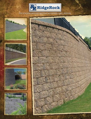
- 1. RidgeRock THE ENGINEERED SEGMENTAL RETAINING WALL SYSTEM
- 2. etaining ock r er The Advantages of RidgeRock abili ty Welcome to g end rid ep Q uali ty &D the ridgerock retaining wall system IN T E GRA L S H E A R KE Y S YS T E M Incorporated in each RidgeRock unit is an integral user friendly concrete shear key for positive block-to-block shear. Located on the bottom of each ste wa l l s y m unit, the incorporation of the shear mechanism into the block eliminates the needs for pins or clips that can be easily forgotten or misplaced. F L E X IBL E W IN G POS IT ION IN G S YS T E M The latest advancement in the RidgeRock product line is the inclusion of the Flexible Wing Positioning System (FWPS). The positioning wings, located on either side of the RidgeRock units, provide additional shear resistance between the integral shear key and the underlying course of block while allowing flexibility in block positioning for easy installation of curved walls. CH IP- A W A Y S H E A R KE Y The integral shear key includes a molded groove to provide easy removal of a predetermined portion of the shear key. Removal of this portion of the shear key allows the construction of walls with a near vertical setback when space is at a premium. OPT ION S IN A PPE A RA N CE RidgeRock is available in beveled face to offer increased shadowing effects or in straight face for clean lines. A variety of color options are available at most locations*. PROV E N S U CCE S S Engineers, architects, municipalities and homeowners have trusted the strength and dependability of RidgeRock for over a decade. RidgeRock can be found in thousands of projects across the country. From 2 ft. planter walls T he RidgeRock Retaining Wall System was patented and introduced geogrid connection strength and drainage capabilities. The integrated to 60+ ft. commercial walls, trust RidgeRock retaining walls block after block. to the marketplace more than a decade ago. Since its debut, the concrete shear key provides dependable block-to-block shear resistance *Available colors and styles vary by region. Please contact your local RidgeRock representative for RidgeRock unit has been a preferred retaining wall product for many without the need for cumbersome, often omitted, clips or pins. available options. contractors. Through advancements in technology and design throughout its existence, the RidgeRock unit has continued to evolve Designed for aesthetics and functionality, the RidgeRock and is now the preferred product of contractors throughout the country. engineered segmental retaining wall system gives your project an attractive and cost effective option that complements any natural T he RidgeRock Retaining Wall System is the latest advancement in landscape. RidgeRock is available in varying colors* and in a straight soil retention technology. The RidgeRock system is universal in design face or beveled face design. With all RidgeRock has to offer, you have and can be used to construct walls from 1 foot to over 60 feet in height. the freedom to create curves, terraces, corners and other complex S T RA IGH T F A CE BE V E L E D F A CE C AP U NI T Dimensions: 8”h x 12”d x 18”w Dimensions: 8”h x 12”d x 18”w Dimensions: 4”h x 12”d x 18”w The patented design of the RidgeRock unit incorporates an integral designs with ease. You are sure to find the perfect solution for your Weight: 79 lbs each** Weight: 78 lbs each** Weight: 65 lbs each** Coverage: 1 sq. ft. per unit Coverage: 1 sq. ft. per unit Coverage: 1/2 sq. ft. per unit concrete shear key to provide block-to-block shear resistance while the project. Setback: 1/2” to 1/8” (modified) per course Setback: 1/2” to 1/8” (modified) per course open core design allows drainage stone containment for superior *Available colors and styles vary by region. Please contact your local RidgeRock representative for available options. ** Weight and other dimensions may vary by location. Please contact your local RidgeRock representative for information.
- 3. Installation Steps STEP 1 BA S E COU RS E PRE PA RA T ION Beginning at the point of lowest elevation, excavate a trench the length of the wall that will accommodate a minimum of 6” of base material and 6” of block embedment. As a rule of thumb for level areas, 1” of STEP 1 block should be embedded for every 8 ft. of wall with a minimum of 6” embedded below grade. If your wall is placed on a slope, check with a local design engineer for requirements. The width of the trench should be a minimum of 24” and your trench depth will vary with wall embedment requirements. STEP 2 L E V E L IN G PA D IN S T A L L A T ION Place and compact a minimum of 6” of base material to 95% of Standard Proctor. Base material should consist of 1/2” to 3/4” washed stone or crushed road base. This material will vary from region to region. STEP 3 BA S E COU RS E IN S T A L L A T ION S T E PS 2 & 3 Place the base course of block end-to-end and use a string line along the back of the block to align straight walls. Center the blocks on the pad to allow a minimum of 6” of pad in front of and behind the blocks. Using a 4 ft. level, level the blocks from side-to-side and front-to-back. Level across 3 full blocks to ensure level from block-to-block. Use a rubber mallet to seat the blocks into the leveling pad rather than attempting to push small amounts of material under the blocks. STEP 4 CORE & D RA IN A GE F IL L Place 1/2” to 3/4” clean aggregate within the cores, the area between blocks and a minimum of 12” behind the back of the blocks. Fill 1 block course at a time as wall construction proceeds. ST EP 4 STEP 5 GE OGRID PL A CE M E N T Level the drainage stone with the top of the block and ensure fill dirt has been placed and compacted to this same elevation. Clean all debris from the top of the block course. Cut the proper length and install with the strength direction of the geogrid perpendicular to the wall face. The strength direction is normally the roll direction, but check withthe geogrid manufacturer for clarification. Extend geogrid to the front of the block. Place next course of RidgeRock on wall in a running bond configuration to hold geogrid in place. Pull geogrid taut from the back, removing any wrinkles. Pin or stake to hold in place while placing fill. Place and compact infill soils leaving 12” behind blocks for drainage fill. Place and compact drainage fill inside and 12” behind blocks. ST EP 5 STEP 6 S U CCE S S IV E COU RS E IN S T A L L A T ION Prior to adding successive courses, the block should be swept free of debris. Starting in the center of the wall, center the block in a running bond pattern and pull it forward until the Shear Key engages the positioning Wings. Place backfill material in maximum 12” loose lifts and compact to 95% of standard proctor leaving 12” of space behind the block for drainage fill. Place drainage fill behind and in blocks 1 course at a time and compact. Only hand operated compaction equipment such as a vibrating plate compactor should be used within 3 ft. of the back of the block. Continue with successive courses, placing geogrid as required by design until full height is reached. S TE P 6 STEP 7 CA PPIN G T H E W A L L Top caps are 4” in height and should be placed with the split edge forward. Adhere top caps with construction adhesive specifically manufactured for masonry use. Cap styles may vary by region. Check with your local representative for options. STEP 8 T OP OF W A L L S T E PPIN G Where steps must occur in the top of the wall to follow finished grades, double capping at each step can be used to provide a finished appearance. S T EP S 7 & 8 IN S T A L L A T ION N OT E S These application steps are applicable to most situations. However, special design considerations must be given in some instances to ensure hydrostatic forces do not develop and that conditions behind of and in front of the wall are handled correctly. These instances include but are not limited to ponding water, sloping grades, surcharge conditions, fences and guardrails, tiered walls, driveways and roads, groundwater, culverts, bridges, drainage structures and streams or creeks.
- 4. SLOPING FILL LEVEL GRADE LEVEL GRADE 250 PSF SURCHARGE 3 ft. Design Charts and Details NO SURCHARGE Geogrid length (L) Geogrid length (L) Geogrid length (L) Design Design Design Height Height Height R EI N FO R C E D WA LL DET A IL GR AV ITY WAL L S (Maximum Unreinforced Wall Height) E4 (H) E4 (H) E4 (H) E3 E3 E3 12” 4” cap unit E2 E2 E2 NEAR VERTICAL 3.58° +/- BATTER E1 E1 E1 12” Level Fill 3H:1V Slope Level Fill 3H:1V Slope Leveling pad Leveling pad Leveling pad Sand/Gravel 2’-8” 2’-0” 3’-4” 2’-8” CASE 1 CASE 2 CASE 3 Ф=34° Geogrid reinforcement Silty Sand D E S IGN A S S U M PT ION S & N OT E S Silt/Lean Clay: Ф=26° γ=120 pcf Ф=30° 2’-8” 2’-0” 2’-8” 2’-0” • Design charts are applicable only to soils possessing an angle of internal friction (PHI) of 26°, Height 30° and 34° and a moist unit weight of 120 lbs./cu.ft. For other soil types consult a local Case 1, Level fill, No loading Silt/Clean Clay 2’-0” 2’-0” 2’-0” Drainage material varies Ф=26° 2’-0” design engineer. Design Geogrid Geogrid Elevations (Feet above base) (1/2 “ to 3/4” crushed stone) • It is assumed that wall construction is in accordance with RidgeRock specifications and Height (ft.) Length (ft.) E-1 E-2 E-3 E-4 E-5 E-6 industry standards. All backfill soils are assumed compacted to 95% of standard proctor and placed in maximum 8” compacted lifts. 4 5.0 2 Reinforced soil *SEE NOTE. • Gravity wall calculations assume no sloping fill or surcharges within a distance of 2 times the 6 5.5 2 4 wall height behind the wall. 8 7.0 2 4 6 --- • Gravity wall calculations assume the use of free draining 1/2” to 3/4” stone for the leveling pad 10 8.0 0.67 2 4 6 8 COR NER D ETAIL and 12” behind the facing units. 12 9.5 0.67 2 4 6 8 10 4” dia. perforated drain pipe 6” min. • Unreinforced heights may be increased with the use of additional drainage aggregate in some cases. Contact RidgeRock Retaining Walls Inc. or a qualified engineer for more information. Case 2, Level fill, 250 psf surcharge Base leveling pad Successive course • The geogrid charts are provided for setback construction only. Setback construction is a wall Design Geogrid Geogrid Elevations (Feet above base) 24” minimum Lower built with a 1/2” positive setback per course of block. For near vertical construction consult Height (ft.) Length (ft.) E-1 E-2 E-3 E-4 E-5 E-6 *EMBEDMENT BELOW GRADE VARIES WITH course Construction the RidgeRock website for design charts or a qualified engineer for geogrid requirements. 4 5.0 0.67 2 CONDITION IN FRONT OF WALL. 6” MINIMUM. • Geogrid lengths shown are measured from the face of the block to the tails of the geogrid. 6 7.0 2 4 • Wall heights shown in the design charts are measured from the top of the leveling pad to the 8 8.5 0.67 2 4 6 top of the top most 8” block course. 10 10.0 0.67 2 4 6 8 • Design charts provide geogrid requirements in 2 ft. wall height increments. Judgment will be 12 11.5 0.67 2 4 6 8 10 NEA R V E R TI CA L DET A IL (0.9° BATTER ) required when interpolating between these heights. • Geogrid charts are based on the use of GridLok 270 coated polyester geogrid with a design Case 3, 3H:1V Sloping fill 12” 4” cap unit strength (LTDS) of 1475 lb/ft. per the NCMA Design Manual for Segmental Retaining Walls, Design Geogrid Geogrid Elevations (Feet above base) Split with chisel and hammer 3rd Edition. Information on other specific geogrid is available through the manufacturer. Height (ft.) Length (ft.) E-1 E-2 E-3 E-4 E-5 E-6 • Information provided in the design charts is for informational purposes only. A qualified 12” Corner Block Creation engineer should be consulted for final wall design purposes. RidgeRock Retaining Walls Inc. 4 5.5 2 Height accepts no liability for the improper use of these charts. 6 6.5 2 4 Drainage material varies (1/2 “ to 3/4” crushed stone) 8 8.0 0.67 2 4 6 10 10.0 0.67 2 4 6 8 Backfill soil Saw cut Silty Sand: Ф=30° γ=120 pcf 12 11.5 0.67 2 4 6 8 10 4” dia. perforated drain pipe 6” min. NOTE: PREFABRICATED CORNER UNITS MAY ALSO BE AVAILABLE IN SOME LOCATIONS. Case 1, Level fill, No loading Sand/Gravel: Ф=34° γ=120 pcf Design Geogrid Geogrid Elevations (Feet above base) Base leveling pad Height (ft.) Length (ft.) E-1 E-2 E-3 E-4 E-5 E-6 Case 1, Level fill, No loading 24” minimum Design Geogrid Geogrid Elevations (Feet above base) 4 4.0 2 6 5.0 2 4 Height (ft.) Length (ft.) E-1 E-2 E-3 E-4 E-5 E-6 8 6.0 2 4 6 4 4.0 2 10 7.5 2 4 6 8 6 4.5 2 4 SET B A C K D E T A IL (3.58° BA T T ER) 8 6.0 2 4 6 R AD IUS D ETAIL 12 8.5 0.67 2 4 6 8 10 10 7.0 2 4 6 8 12” 4” cap unit 12 8.0 2 4 6 8 10 OPTION A - 9' 0" RADIUS Case 2, Level fill, 250 psf surcharge No block modifications required Case 2, Level fill, 250 psf surcharge 12” Design Geogrid Geogrid Elevations (Feet above base) 3.58° OPTION B - 6' 4" RADIUS Height (ft.) Length (ft.) E-1 E-2 E-3 E-4 E-5 E-6 Design Geogrid Geogrid Elevations (Feet above base) Remove tips of sidewings 4 4.5 0.67 2 Height (ft.) Length (ft.) E-1 E-2 E-3 E-4 E-5 E-6 OPTION C - 2' 2" MINIMUM RADIUS Drainage material Remove wings and bottom lug 6 6.0 2 4 4 4.5 2 (1/2 “ to 3/4” crushed stone) Height 6 5.0 2 4 varies 8 7.0 2 4 6 10 8.5 0.67 2 4 6 8 8 6.5 2 4 6 Backfill soil 12 10.0 0.67 2 4 6 8 10 10 7.5 2 4 6 8 12 8.5 0.67 2 4 6 8 10 NOTE: RADII SHOWN ARE MEASURED 4” dia. perforated drain pipe 6” min. AT TOP OF WALL. RADII AT BOTTOM OF Case 3, 3H:1V Sloping fill Case 3, 2H:1V Sloping fill WALL WILL NEED TO BE INCREASED TO ACCOUNT FOR WALL BATTER. Design Geogrid Geogrid Elevations (Feet above base) Design Geogrid Geogrid Elevations (Feet above base) Base leveling pad Height (ft.) Length (ft.) E-1 E-2 E-3 E-4 E-5 E-6 Height (ft.) Length (ft.) E-1 E-2 E-3 E-4 E-5 E-6 24” minimum 4 4.5 2 4 4.0 2 6 5.5 2 4 6 5.5 2 4 8 7.0 2 4 6 8 7.0 2 4 6 10 9.0 0.67 2 4 6 8 10 9.0 0.67 2 4 6 8 12 10.5 0.67 2 4 6 8 10 12 10.5 0.67 2 4 6 8 10
- 5. The RidgeRock Family of Products R I DG E R O C K II With the same flexibility in design and including the same Flexible Wing Positioning System as its larger RidgeRock predecessor, RidgeRock II is a popular choice for all of your retaining wall needs. B EL GAD O When you are looking for something on a grander scale, look to the Belgado retaining wall system. This system offers a multi- piece appearance with variegated colors for a prestigious and luxurious finish. RI DG E S C A PE In a word...GREEN! The RidgeScape reinforced earth system is perfect for those areas where the desired finished appearance is not one of concrete or stone but where level space is still at a premium. Vegetated after construction, this system allows near vertical construction without sacrificing a natural, eco- friendly appearance. Call your local RidgeRock representative to learn more about how RidgeRock Retaining Walls can meet your most challenging site development and landscaping needs. RidgeRock Distributed by: Retaining Walls, Inc. P.O. Box 241233 Charlotte, NC 28224 office 704.504.3358 fax 704.504.3038 www.Ridge-Rock.com Patent Nos. 6,168,354 & 6,474,036 Other Patents Pending