
Empfohlen
Weitere ähnliche Inhalte
Was ist angesagt?
Was ist angesagt? (20)
Andere mochten auch
Andere mochten auch (9)
Ähnlich wie Chapter 12
Ähnlich wie Chapter 12 (20)
Kürzlich hochgeladen
Kürzlich hochgeladen (20)
Chapter 12
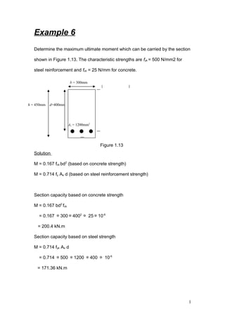
- 1. Example 6 Determine the maximum ultimate moment which can be carried by the section shown in Figure 1.13. The characteristic strengths are fyk = 500 N/mm2 for steel reinforcement and fck = 25 N/mm for concrete. Solution M = 0.167 fck bd2 (based on concrete strength) M = 0.714 fy As d (based on steel reinforcement strength) Section capacity based on concrete strength M = 0.167 bd2 fck = 0.167 ∗300∗4002 ∗ 25∗10-6 = 200.4 kN.m Section capacity based on steel strength M = 0.714 fyk As d = 0.714 ∗500 ∗1200 ∗400 ∗ 10-6 = 171.36 kN.m 1 b = 300mm As = 1200mm2 h = 450mm d=400mm Figure 1.13
- 2. The maximum ultimate moment which can be carried by the section is 171.36 kN.m analysis of doubly reinforced section When doubly reinforced section is taken into consideration, the compression and the tension steel bars should yield before the concrete. To ensure that the compression steel bar have been yielded d'/x should be less than 0.38 (for fyk = 500 N/mm2 ) as shown in the analysis performed on the doublly reinforced section shown in Figure 1.14. Assume steel reinforcement in compression area are yielded εsc= 0.987 fyk / Es = 0.87 ∗500 /200000 = 0.00217 0.0035 / x = 0.00217 /( x-d') (x – d') / x = 0.00217 / 0.0035 2 As′ As x d-x N.A 0.0035 Est εsc d' x-d' Figure 1.14
- 3. 1 – (d' / x) = 0.62 d' / x = 0.38 for other grades of steel, with x = 0.45d d' / d = 0.171 If d'/ x > 0.38 (or d'/d > 0.171), then it is necessary to determine the value of εsc from strains distribution, then and then to compute fsc from fsc = Es xεsc where Es = 200 000 N/mm2 LIMITING CONSTANT VALUES TABLE Example 7 Compute the design strength (the ultimate moment of resistance) of the doubly reinforced cross-section as shown in Figure 1.15; fyk = 460 N/mm2 and fck = 30 N/mm2 3 b=280mm As' = 620mm2 As = 2410mm2 d = 510mm d' =50mm Figure 1.15
- 4. Solution Form equilibrium. Fst = Fcc + Fsc (assume that the steel reinforcement in the tension and compression are yielded values ( fst = fsc = 0.87 fyk) 0.87 fyk As = 0.567 fck b ∗ 0.8 x + 0.87 fyk As' x = 0.87 fyk (As – As') / 0.4536 fck b x = 0.87 ∗ 500 (2410 – 628) / 0.4536 ∗25 ∗280 x = 244.1 mm < 0.617d ( = 314.67mm) Therefore, steel reinforcement in tension will have yielded as assumed d' / x = 50 / 244.1 = 0.20 < 0.38 So the steel reinforcement in the compression will have yielded as assumed. Taking moment about the centroid of the steel in tension M = Fcc x Z1 + Fsc ∗Z2 M = 0.567 fck b ∗0.8 x (d – 0.8x / 2) + 0.87 fyk As' (d – 50) = [0.567 x 25 x 280 x 0.8 x 244.1 (510 – 0.8 x 244.1/ 2)] + 0.87 x 500 x 620 (510-50) ∗10-6 = 443 KN. m 4 As′ As 0.567fck Fst N.A Z2=d-50 Z1=d-0.8x/2 Fsc Fcc0.8xx
- 5. DESIGN OF REINFORCED BEAMS Reinforced Beams design consists primarily of producing member details which will adequately resist the ultimate bending moments, shear forces and torsional moments. At the same time the serviceability requirements must be considered to ensure that the member will behave satisfactorily under working loads. The design procedure should include the following: 1- Preliminary analysis and member sizing; 2- Detailed analysis and design of reinforcement; 3- Serviceability calculations. Preliminary analysis and member sizing While starting to design a beam the dimensions to be taken care of are the 1- Cover to the reinforcement; 2- Breadth (b) 3- Effective depth (d) 4- Overall depth (h) For reinforced concrete beams the span-depth ration varies from 14 to 30 but it is slightly greater for larger spans. 5
- 6. 6
- 7. EC2 fig. BS Fig. Derivation of Designing equations BY EC2 Force= stress ∗ area Fs = 0.87 fyk As Fc = 0.567 fck ∗b ∗0.8x = 0.454 fck b x For equilibrium Fc= Fs [0.454 fck b x = 0.87 fyk As] ∗ d 1 d x = 1.916 ∗ f yk fck ∗ bd As M = Fc ∗z b dh As Z=d-0.4x Fs Fc 0.567fck N.A 7 Figure 1.16
- 8. = (0.454 fck b x) (d - 0.4 x) Rearrange the above formulae = (0.454 d x ) (1-0.4 x) fck b d2 Assume; k= (0.454 d x ) (1-0.45 x) ∴ M=kfckbd2 ( the applied bending moment on the section) Where the simplified stress block is used; EC2 limits d x should not exceed 0.45 and x d′ (for doubly reinforced section) should not exceed 0.38 (for fy=500 N/mm2 ). This limit in d x and x d′ is to ensure that the steel reinforcement will have yielded (fs=0.87fyk) and the design will be under reinforced section. Therefore, the maximum moment capacity of a singly reinforced beam based on concrete strength is calculating form (limiting x=0.45d) ∴Mu = 0.167 fck bd2 (the maximum moment capacity of singly reinforced beam based on concrete stregth), where k′ = 0.167. Derivation of doubly reinforced beams equations Whenever the applied moment exceeds the maximum moment capacity of the section then the excess (M-Mu) to be resisted by using steel reinforcement (As 8
- 9. ′) in the concrete compression area to supplement the load-carrying capacity of the concrete. The neutral axis depth (x) to be maintained at the maximum permitted value i.e 0.45d. By referring to the Figure 1.17: F s′ = 0.87 fyk As′ M-Mu=Fs′ ∗ z1 = 0.87 fyk As′ ∗ (d-d′) − =′ ′−yk M Mu As 0.87 (d d )f Where Mu= k′ fcu bd2 ∴ ′− =′ ′− 2M k bdfcu As 0.87 (d d )f yk An area of steel in tension must then provided to balance the total compressive forces in concrete and the compression reinforcement: Fs=Fs′ + Fc 0.87 fyk As = 0.87 fyk As′ + 0.204 fck bd b dh As Z=d-0.4x Fs Fc 0.567fck N.A As′ d′ Fs′ z1 =d-d′ 9 Figure 1.17
- 10. ∴ = + ′ 0.204 bdfck AsAs 0.87f yk Where; Mu=0.204 fck b d∗z ∴ z = + ′ yk Mu AsAs 0.87f Note: to prove that z= d {0.5+ 0.25 1.134k− }; refer to Figure 1.16 M = Fc ∗ z = 0.567 fck b∗ 0.8x ∗z Where; z = d - 0.8x 2 and 0.8x = 2 (d-z) ∴M= 0.567 fck b∗ 2 (d-z) ∗ z = 0.1.134 fck b (d-z) ∗ z Where; k = dbfcu M 2 ∗∗ = − 2 2 k z z 1.134 d d And (z/d)2 – (z/d) + k/0.9 = 0 Solve the above quadratic equation z= d {0.5+ 0.25 1.134k− } note: the above equations are also applicable to flanged beams where the neutral axis lies within the flange. Designing procedures for singly reinforced beams 10
- 11. 1. Check that k = ,max ,min 100 4.0% 100 26 % s s ctm yk A bh A f bd f ≤ ≥ ≤ < Kbal = 0.167 2. Determine the lever-arm, z, from the following equation z= d {0.5+ 0.25 1.134k− } 3. Calculate the area of tension steel required from As= M 0.87 zf yk 4.Select sutable bar size. 5. Check that the area of steel actually provided is within the limits required by thecode that is, ,max 100 4.0%sA bh ≤ and ,min 100 26 %s ctm yk A f bd f ≥ and not less than 0.13% where fctm = 0.3 x fck 2/3 for fck ≤ C50. Example 8 The ultimate design moment to be resisted by the section in the Figure 1.18 is 165 kN.m. Determine the area of tension reinforcement (As) required. The characteristic strength of steel fyk=500 N/mm2 and the characteristic strength of concrete fck = 25 N/mm2 : 11 b=230mm d= 490mm h= 550 mm As
- 12. Solution 1. k = ∗ ∗ 2 M b dfck = 6 2 165*10 25*230*490 = 0.12 < 0.167 Therefore, the section is singly reinforced: 2. z= d {0.5+ 0.25 1.134k− } = d {0.5+ 0.25 0.12 1.134− } = 0.88d < 0.954 d 3. As= M 0.87 zf yk = ∗ = ∗ ∗ 6 2 165 10 880 mm 0.87 500 431 4. Provide 3 H20 bars, area= 920 mm2 5. 100 943 0.84 0.13% 230 490 ∗ = = > ∗ s100A bd and 100 943 0.75 4% 230 550 ∗ = = < ∗ s100A bh . Example 9 Design the steel reinforcement for the section of dimension; 230 mm wide and 330 mm effective depth, while the inset of compression steel is 50 mm. the section to resist an applied moment of 165 kN.m. Solution 12 Figure 1.18
- 13. 1. k = ∗ ∗ 2 M b dfck = 6 10 *25 ∗ 2 165 230 *330 = 0.26 > kbal (=0.167) Therefore, compression steel reinforcement is required z= d {0.5+ 0.25 0.167 1.134− } 0.82 d (zmin) < 0.821 d < 0.954 d (Z max) ∴z = 0.821 d = 0.821 ∗330 = 232.8 mm x = 0.45d = 0.45 x 330 = 148 mm d 50 0.34 0.38 x 148 ′ = = < ∴The compression steel will have yielded 2. 2(k-k ) bdf ck 0.87 (d-d )f yk ′ =′ ′As = 2 (0.26-0.167) 25 230 330 0.87 500 (330 50) ∗ ∗ ∗ ∗ ∗ − = 496 mm2 Provide 2 H20 bars for As', area= 628 mm2 3. As = 2 ck yk k f bd As 0.87f z ′ ′+ = 2 0.167 25 230 330 496 0.87 500 0.82 330 ∗ ∗ ∗ + ∗ ∗ ∗ 13
- 14. = 1384 mm2 Provide 3 H25 bars for As, area= 1470 mm2 . 4. Check area of steel required and provided for ductility. (As' prov – As' req) > (As prov – As req) 628 – 496 (= 132 mm2 ) > 1470 – 1384 (= 86 mm2 ) 5. 100 943 0.84 0.13% 230 490 ∗ = = > ∗ s100A bd and 100 943 0.75 4% 230 550 ∗ = = < ∗ s100A bh . 1.8 Derivation of design formulae for flanged reinforced concrete beams: The design procedure of flanged beam depends on the location of the neutral axis. The neutral axis may lie in the flange or in the web as shown in the Figure 1.19 xhf d bf N.A N.A x a) Neutral axis in the flange b) Neutral axis in the web 14 Figure 1.19
- 15. A) Neutral axis in the flange Z= d – (0.8/2)x Or 0.8x = 2(d-z) If 0.8 x ≤ hf ∴the neutral axis does lie within the flange as assumed and As= M 0.87 zf yk B) The neutral axis in the web Fcf = 0.567fck ∗ hf ∗ (b-bw) Fcw = 0.567fck ∗0.8x∗bw Where; d x = 0.45 xhf d bf N.A 0.8x Fc 0.4x Fs Z=d-0.4x x hf d bf N.A 0.8x Fcf 0.567fck Fs Z1 Fcw Z2 bw 15
- 16. x = 0.45∗d 0.8 x = 0.8∗0.45d Therefore, Fcw=0.36 fck bw d Z1 = d – 0.5 hf Z2 = d – 0.5 ∗(0.8x – hf)/2 = d – 0.5 ∗0.45d = 0.775 d Fs = 0.95 fy As The moment about the centroid of the flange at Fcf M = Fs ∗(d – hf/2) - Fcw ∗(s/2 – hf/2) = 0.87fykAs (d - 0.5hf)-0.2 fck bw d (0.36d - hf) /2 Therefore, As = ( ) ( ) + ck w f yk f M 0.1f b d 0.36d-h 0.87f d-0.5h As stated in the EC2; the above equation to calculate As for singly reinforced flanged section only when hf< 0.36d. For section with tension reinforced only; the applied moment must not exceed the moment of resistance of the concrete which can be calculated as following: M = Fcf.z1+Fcw.z2 = 0.567 fck (b-bw) (d-0.5hf)+ 0.167 fck bw d2 Thus; = − − + ÷ ÷ f f 2 cu M h b bhw w0.567 1 1 0.156 f bd d b 2d b or M = βf fcubd2 Where βf can be obtained from Table 3.6 of the BS8110 The equation for the steel area As only applies when the ultimate moment to be resisted by the section is less than βf fcubd2 . If the applied moment is 16
- 17. greater than the resistance moment of the concrete section then the excess (M-Mu) to be resisted by steel reinforcement in the compression area: ∴ M – Mc = Fs′ ∗z Where z = (d-d′) and Fs′ = 0.87 fyk As′ ∴ M – Mc = 0.87 fyk As′ (d - d′) As′ = ′− u yk M-M 0.87f (d d ) For equilibrium; Fs = Fcf + Fcw +Fs′ So that: As = ( )+ − + ′ cu ckw f w 0.2 d 0.567b b bf f hf As0.87f yk Take note that x d′ should be less than 0.38 to ensure that the steel in compression area will have yielded. Example 10 x hf d bf N.A 0.8x Fcf 0.567fck Fs dFcw bw Fs′ d′ 17
- 18. A ‘T’ beam has effective flange width 900 mm, flange thickness 150 mm, web width 250 mm, and overall depth 500 mm. characteristic strength for concrete 30 N/mm2 and for steel 500 N/mm2 . Assume that the centroid of reinforcement is placed 50 mm from the top or bottom of the beam, design suitable reinforcement for ultimate design moments The concrete grade is 25 N/mm2 : a) 800 kN.m, b) 950 kN.m, c) 1000 kN.m Solution a) Determine the location of the neutral axis: the moment resistance of the flange (Mf): Mf= 0.567 fck bf hf (d-hf/2) = [ ] 6 0.567 25 900 150 (650 (150/ 2) 10− ∗ ∗ ∗ ∗ − ∗ = 909.0 kN.m > the applied moment (=600 kN.m) ∴the neutral axis lies within the flange 2 ck M k bd f = = 6 2 600 10 900 550 30 ∗ ∗ ∗ = 0.088 < / k (=0.167) ∴ the section is singly reinforced section z d{0.5 0.25-k/1.134}= + = d{0.5 0.25-0.088/1.134}+ = 0.915d < zmax (=0.954d) 18
- 19. z = 0.915 x 550 = 503.3 mm yk M As 0.87f z = = 6 600 10 0.87 500 503.3 ∗ ∗ ∗ = 2740.67 mm2 b) Mf (=909 kN.m) < 950 kN.m ∴the neutral axis lies within the web 2 ck f f w f ck awMc 0.567f h (b b )(d-0.5h ) 0.167f b d= − + = 2 6 0.567 25 150 (900 250)(650 0.5 150) 0.167 25 250 650 10− ∗ ∗ ∗ − − ∗ + ∗ ∗ ∗ ∗ = 1235 > 950 kN.m ∴the section is singly reinforced section hf (=150 mm) < 0.36d (0.36∗650=234) As = ( ) ( ) + ck w f yk f M 0.1f b d 0.36d-h 0.87f d-0.5h = 6 950 10 0.1 25 250 650 (0.36 650 150) 0.87 500 (650 0.5 150) ∗ + ∗ ∗ ∗ ∗ ∗ − ∗ ∗ − ∗ = 3935 mm2 c) Mc (=1235 kN.m) < 1300 kN.m 19 1 2 2 x
- 20. ∴the section is doubly reinforced section x = 0.45d = 0.45∗650 = 292.5 mm / d 50 0.171 0.38 x 292.5 = = < ∴the compression reinforcement will have yielded / / yk M-Mc As 0.87f (d-d ) = = 6 (1300 1235) 10 0.87 500(650 50) − ∗ ∗ − = 249 mm2 /ck w ck f f w yk 0.2f b d 0.567f h (b -b ) As As 0.87f + = + = ≥ = 5294 mm2 1.10 Minimum and maximum percentages of reinforcement in beams and minimum clear spacing between bars: As stated in cl. 5.4.2.1.1(1) of the EC2, the minimum required percentages of tension reinforcement should not be less than the required to control cracking as stated in cl. 4.4.2 and the value of 0.6 t yk b d f should be greater than or equal to 0.0015 tb d where bt is the width of the surface under tension. For a T-beam 20
- 21. with the flange in compression, the width of the web is taken into account. When the maximum percentage of reinforcement is considered cl. 5.4.2.1.1(2) can be referred to and realized that the sum of the tension and compression reinforcement should not exceed 4% of the cross-sectional area of the beam itself. As stated in cl.5.2.1.1 of the EC2, the minimum spacing of bars should be the greater of the bar diameter, largest aggregate size plus 5 mm or 20 mm. Example 11 A simply supported beam of 7 m span carries a characteristic dead load of 10 kN/m and live load of 5 kN/m. The beam dimensions are breadth 250 mm, effective depth (d) 450 mm and overall height (h) 500mm. The concrete grade is 35 N/mm2 and the steel grade is 460 N/mm2 , while the nominal cover is 37.5 mm. The maximum aggregate size is 20 mm, design the beam to resist the design flexural moment Solution Design load = 1.35∗10+1.5∗5 = 21 kN/m 21 7m 21 kN/m
- 22. 134.75 kN.m Ultimate moment = 8 2wl = 2 21 7 8 ∗ = 134.75 kN.m cu 2 fbd M k = = 6 2 128.625 10 250 450 35 ∗ ∗ ∗ = 0.073 k ( 0.167)′< = ∴singly reinforced section z d{0.5 0.25-k/1.134}= + = d{0.5 0.25-0.073/1.134}+ = 0.931d < zmax (=0.954d) z 0.931 450= ∗ = 419.1 mm (d-z) x 0.4 = = (450-419.1) 0.4 22
- 23. = 77.25 mm < 0.45d (0.45 ∗450=202.5mm), ∴tension steel reinforcement will have yielded yk M As 0.87f z = = 6 128.625 10 0.87 500 419.1 ∗ ∗ ∗ = 705.53 mm2 100 50025013.0 Asmin ∗∗ = Or 0.6bd/fyk > 0.0015bd = 162.5 mm2 500250 100 4 Asmax ∗∗= = 5000 mm2 min maxAs ( 162.5) As( 705.53) As ( 5000)= < = < = adjust use steel bar size 25 mm; Area of one steel bar = =∗µ2 5.12 490.87 mm2 No. of steel bars = 705.3 490.87 = 1.43 2≅ As provided = 2∗490.87 = 981.74 mm2 spacing between bars = 1 2522.372250 ∗−∗− = 125 > hagg max. +5 (=20+5=25mm) 232Y25