Brooks Ar-Mite Low Flow Armored Flowmeter
•
1 gefällt mir•1,084 views

The Brooks® Ar-MiteTM is a reliable, low flow metal tube flowmeter with 316L stainless steel wetted parts. The magnetically coupled indicator provides a highly reliable method of indication. This model is a practical and economical approach to low flow rate indication for high pressure and difficult to handle fluids. Optional accessories include 4-20 mA output, Needle Valve, Flow Controllers and Alarms.

Empfohlen
Empfohlen
Weitere ähnliche Inhalte
Was ist angesagt?
Was ist angesagt? (20)
Andere mochten auch
Andere mochten auch (8)
Ähnlich wie Brooks Ar-Mite Low Flow Armored Flowmeter
Ähnlich wie Brooks Ar-Mite Low Flow Armored Flowmeter (20)
Mehr von Belilove Company-Engineers
Mehr von Belilove Company-Engineers (20)
Kürzlich hochgeladen
Kürzlich hochgeladen (20)
Brooks Ar-Mite Low Flow Armored Flowmeter
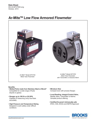
- 1. 1 Brooks® Ar-MiteTM MT3750C Data Sheet DS-VA-MT3750C-eng October, 2014 Ar-MiteTM Low Flow Armored Flowmeter Ar-MiteTM Model MT3750 Metal Tube Flowmeter with Transmitter or Inductive Alarm Ar-MiteTM Model MT3750 Metal Tube Flowmeter Benefits: • Wetted Parts made from Stainless Steel or Monel® Compatible for a wide range of fluids (liquids or gases) • Ranges up to 100 I/h or 26 GPH Capable of measuring (very) low flows accurately • High Pressure and Temperature Rating Designed to work safely under difficult conditions • Miniature Size Compact even with process flanges • Local Reading, Integral Control Valve, Needle Valve, Transmitter or Alarms Versatile product offering • Certified Ex-proof, Intrinsically safe ATEX, CSA, IECEx and NEPSI Approved
- 2. 2 Brooks® Ar-MiteTM MT3750C Data Sheet DS-VA-MT3750C-eng October, 2014 Description The Brooks® Ar-MiteTM is a reliable, low flow metal tube flowmeter with 316L stainless steel wetted parts. The magnetically coupled indicator provides a highly reliable method of indication. This model is a practical and economical approach to low flow rate indication for high pressure and difficult to handle fluids. Optional accessories include 4-20 mA output, Needle Valve, Flow Controllers and Alarms. Specifications Performance Specifications Flow Liquids up to 100 l/h or 26 GPH (Water equiv.) Gases up to 3.1 m3 n/h or 120 SCFH (Air equiv.) (See Table 1 for more information) Accuracy ±5% Full Scale, Class 4 to VDE/VDI 3513, Optional ±3% Full Scale, Class 2.5 to VDE/VDI 3513 Repeatability 1% full scale Pressure Ratings Maximum fluid pressure: All non-flanged meters: 1500 psig (100 bar) Flange connections: (Refer to Table 2) Optional maximum operating pressure: 4000 psig (276 bar) (no valve, 1/4" NPT option only) Scales Length - 52mm, nominal Types - Detachable aluminum direct reading scales in engineering and reference units Operating Fluid Temperature Limits Indicator: -58°F(-50°C) to 400°F (204°C) Alarm: -20°F(-29°C) to 250°F (120°C) Transmitter: -20°F(-29°C) to180°F (82°C) Ambient Temperature: Indicator: -58°F(-50°C) to 150°F (65°C) Alarm: -20°F(-29°C) to 150°F (65°C) Transmitter: -20°F(-29°C) to150°F (65°C) Refer to Table 3 Materials of Construction: Process Wetted 316L stainless steel (1.4404), Inconel® 625, Titanium Grade II (Size 0 float only) Optional Monel® K-500 (size 1-6 only) O-rings Standard: Viton® fluoroelastomers; Option: Buna-N, Ethylene Proplylene, Kalrez® , PTFE Teflon® (without valve) Enclosure Ratings All Housings Epoxy painted die cast aluminum, Indicator Housing: Type 4X/ IP65 Transmitter Enclosure: Type 4X/ IP66/ IP67 Reed Switch Enclosure: Type 4X Inductive Alarm Enclosure: Type 4X/ IP65 Connections Fittings Horizontal 1/4" NPT Female Threaded 1/4" Tube Compression 6mm Tube Compression 1/4" ISO RC (Refer to Figures 5 thru 7) Flanges EN1092 DN15 to DN25 PN40 RF ANSI B16.5 1/2", 3/4" or 1" - 150# , 300# , 600# RF Vertical Inlet and Outlet Only (Refer to Figures 5 thru 7) Pressure Equipment Directive (PED) 97/23/EC Flow meter complies under Sound Engineering Practices (SEP). Optional Equipment Cartridge or NRSTM Needle Valves The cartridge needle valve can be supplied integrally mounted to the inlet fitting of the instrument. The optional NRS needle valve, also integrally mounted to the inlet fitting, provides a greater number of turns affording precision control. Limit Switches Inductive Alarm Switch One or two electronic limit switches type SJ2-N can be installed in the indicator housing to allow initiation of signaling or switching functions on a preset flow value being reached. The SJ2-N limit switch operates as a slot initiator that is inductively actuated by a cam mounted to the pointer. Any flow value can be used for setting the limit value by sliding the switch along the slot in the mounting plate for the initiators. Minimum setting distance between two limit switches is approximately 50 % of the scale range. (Refer to Figure 3) Power supply 8 Vdc (Max. 15,5 Vdc) Current consumption active area clear: > 3 mA Current consumption active area obscured: < 1 mA Self inductance 29 µH Self capacitance 20 nF Max Temp 158°F(70°C) The flow valve can be used for setting the limit value by sliding the switch along the slot in the mounting plate for the initiators. Minimum setting distance between two limit switches is approximately 50% of the scale range. (Refer to Figure 1).
- 3. 3 Brooks® Ar-MiteTM MT3750C Data Sheet DS-VA-MT3750C-eng October, 2014 Table 3 Fluid Temperature at Ambient Temperature Table 2 Pressure Ratings in PSIG (Bar G) Notes: 1. At ambient temperatures less than 104°F (40°C), the maximum fluid temperature does not increase . 2. Ambient temperature is limited to 150°F (65°C) maximum. MAX. AMBIENT MAX. FLUID TEMPERATURE PER OPTION TEMPERATURE INDICATOR ALARM TRANSMITTER ° F ° C ° F ° C ° F ° C ° F ° C 104 40 400 204 250 120 180 82 110 43 390 199 250 120 175 79 120 49 380 193 250 120 170 76 130 54 370 187 250 120 165 74 140 60 360 182 240 115 155 68 150 65 350 176 235 112 150 65 FLANGE RATING -20°F TO 100°F -29°C TO 39°C 200°F 93°C 300°F 149°C 400°F 204°C 150# 275 (19) 240 (16) 215 (15) 195 (13) 300# 720 (49.5) 620 (43) 560 (39) 515 (35) 600# 1440 (99) 1240 (85) 1120 (77) 1030 (71) GPH l/h In/h SCFH m3n/h CP mBar Inches WC 0 0.021-0.21 0.08-0.8 3.9-39 0.15-1.5 - 5 12 4.8 1 0.034-0.34 0.13-1.3 5.6-56 0.21-2.1 - 10 12 4.8 2 0.095-0.95 0.36-3.6 13.0-120 0.5-4.9 - 20 12 4.8 3 0.29-2.8 1.0-10 - 1.2-12 0.033-0.33 35 12 4.8 4 0.55-5.5 2.1-21 - 2.5-23 0.063-0.62 70 32 12.8 5 1.1-11 4.2-42 - 5.4-53 0.15-1.3 100 38 15.3 6 2.8-26 11-100 - 12-110 0.31-3.1 130 44 17.7 MeterSize Viscosity Limit Pressure Drop Flow Range Water Table 1 Capacities Notes: 1. Air flows in scfm converted to 70o F and 14.7 psia when the meter is operated at 70o F and 14.7 psia. 2. Air flows in m3 n /h (converted to normal conditions: 0o C and 1.013 bar abs) when the meter is operated at 1.013 bar abs and 20o C. Air (1,2)
- 4. 4 Brooks® Ar-MiteTM MT3750C Data Sheet DS-VA-MT3750C-eng October, 2014 Inductive Alarm Electrical Classification Intrinsic safety; ATEX: KEMA 02ATEX1126 II 2 G Ex ia IIC T6 per EN 60079-0: 2006 EN 60079-11: 2007 EN 61241-0: 2006 EN 61241-11: 2006 II 2 D Ex iaD 21 IP65 T 75O C IECEx KEM 09.0046 Ex ia IIC T6 Gb/Ex ia IIIC T 75O C Db IP65 per IEC 60079-0: 2007-10 IEC 60079-11: 2006 IEC 61241-11: 2005 CSA: (USA and Canada) 1379260 Class I, II, III, Div. 1, Groups A thru G, T6 per CSA -157:1992 ; UL913:2002 Class I, Zone 0, Zone 1 AEx ia IIC, T6 per ANSI/ UL 2279: 1996 Ex ia IIC per CSA E79-0:2002; CSAE79-11:2002 NEPSI: (China) GYJ11.1639 Ex ia IIC T6 Gb per GB3836.1-2010; GB3836.4-2010 GOST-R 0813793 Approval POCC NL.06.B01220 Figure 1 Reed Switch Wiring Diagram Non Incendive; ATEX: KEMA 02ATEX1127 II 3 GD T 75o C EEx nA II T6 per EN60079-15: 2003; EN50281-1-1:1998 CSA: (USA and Canada) 1379260 NI, Class I, II, III, Div. 2, Groups A thru G, T6 per CSA -213:1987 ; UL1604:1995 Class I, Zone 2 AEx nA II, T6 per ANSI/ UL 2279: 1996 Ex nA II per CSA E79-0:2002; CSA E79-15:2002 NEPSI: (China) GYJ13.1315 Ex nA IIC T6 Gc per GB3836.1:2010; GB3836.8:2003 GOST-R 0813793 Approval POCC NL.06.B01220
- 5. 5 Brooks® Ar-MiteTM MT3750C Data Sheet DS-VA-MT3750C-eng October, 2014 Reed Switch Alarm Two reed switches are installed in the alarm housing to provide signaling or switching functions when a preset flow value has been reached. The reed switches provide high, low or dual setpoints and latched output over the full range. The switches are normally adjusted to the desired flow range in the factory. Modifications to the switch settings can be made in the field. Minimum setting distance between two switches is approximately 40% of the scale. (Refer to Figures 1 and 2) Data Reed Switch Maximum Voltage* 175 Vdc, 124 Vac Maximum Current* 250 mA Maximum Contact Rating* 3 Watts (*Maximum Switch Specifications) Electrical Classification Non Incendive: Maximum Voltage 30 Vdc Maximum Current 100 mA Maximum Contact Rating 3 Watts CSA: (US and Canada) NI, Class I, Div. 2, Groups A, B, C and D: Class II Groups F and G, T6 per CSA-213:1987; UL 1604:1995 Intrinsic Safety: Entity parameters Vmax = Ui = 30 Vdc, Imax = Ii = 100 mA, Ci = 0, Li = 0 CSA: (US and Canada) IS Class I, II, III, Div. 1, Groups A thru G, T6 per CSA-157:1992; UL 913:2002 Figure 2 Model MT3750C with Reed Switch Alarm Transmitter: 3750 The transmitter provides accurate magnet angle detection and conversion to a 4 - 20 mA industry standard output signal, based on the position of a float assembly in the flowmeter. This rugged, compact, microprocessor-driven device is capable of providing accurate flow information to your external support systems. The patented magnetic sensor with automatic gain control enables an extremely high dynamic capture range without sacrificing accuracy. (Refer to Figures 3 and 4) Data Certifications: E.M.C. Directive 2004/108/EC according to EN 61326-1: 2006 Flame-proof/ Explosion-proof: Power Supply 28 Vdc, 4-20 mA Ambient Temperature: -25o C < Tamb < 65o C Flameproof/ Explosion-proof ATEX: KEMA 01ATEX2174 II 2 G Ex d IIC T6 II 2 D Ex tD A 21 IP66 T 85o C per EN 60079-0: 2006; EN 60079-1: 2004; EN61241-0: 2006; EN61241:2004 UL: United States and Canada Ul Listed, E73889 XP Class I, Div.1, Groups A, B, C, and D,T6 DIP Class II, Div. 1, Groups E, F, and G per UL 1203: 2000; CSA-30: 1986 Class I, Zone 1 AEx d IIC T6 per UL 2279: 1996 Ex d IIC T6 per CSA E79-0:2002; CSA E79-1:2002 NEPSI: (China) GYJ11.1638X Ex d IIC T6 Gb per GB3836.1-2010; GB3836.2-2010 IECEx: KEM 06.0049 EX d IIC T6 per IEC 60079-0: 2004; IEC 60079-1: 2003 GOST-R 0813793 Approval POCC NL.06.B01220 Figure 3 Model MT3750C with Transmitter / Inductive Alarm
- 6. 6 Brooks® Ar-MiteTM MT3750C Data Sheet DS-VA-MT3750C-eng October, 2014 Intrinsic Safety: Functional parameters Power Supply 8-28 Vdc, Imax= 22 mA Entity Parameters: Ui = 30 V DC, Ii = 100 mA Pi = 750 mW Ci = 0uF Li = 1.8 mH Ambient Temperature: -30o C < Tamb < 65o C ATEX: KEMA 01ATEX1033 II 2 G Ex ia IIC T6 II 2 D Ex iaD 21 IP66/IP67 T70°C II 2 D Ex tD A21 IP66/IP67 T70°C per EN 60079-0: 2006 EN 60079-11: 2007 EN 61241-0: 2006 EN 61241-11: 2006 CSA: (US and Canada) IS Class I, II, III, Div.1, Groups A, thru G, T6 per UL913:2002; CSA -157:1992 Class I, Zone 1 AEx ia IIC T6 per UL 2279:1996 Ex ia IIC T6 per CSA E79-0:2002; CSAE79-11: 2002 NEPSI: (China) GYJ11.1637 Ex ia IIC T6 Gb Ex iaD 21 T70°C per GB3836.1/4-2010, IEC 61241-0:2004, GB 12476.4-2010 IECEx: KEM 06.0037 EX ia IIC T6 per IEC 60079-0: 2004; IEC 60079-11: 1999 GOST-R 0813793 Approval POCC NL.06.B01220 Non Incendive Power Supply 8-28 Vdc, Imax= 22 mA Ambient Temperature: -30°C < Tamb < 65°C ATEX: KEMA 01ATEX1035 II 3 GD T 70°C EEx nA II T6 IP66/67 per EN 60079-15: 2003; EN 50281-1-1: 1998 CSA: (US and Canada) NI Class I, Div.2, Grps A, B, C, and D; Class II Grps F and G, T6 per UL 1604: 1995; CSA-213: 1987 Class I, Zone 1 AEx nA II T6 per UL 2279: 1996 Ex nA II T6 per CSA E79-0:2002; CSA E79-15:2002 IECEx: KEM 06.0037 Ex nA II T6 per IEC 60079-0: 2004; IEC 60079-15: 2005 GOST-R 0813793 Approval POCC NL.06.B01220 Figure 4 Transmitter Wiring Diagram Flow Controllers Brooks flow controllers with or without brackets can be integrally mounted on the inlet or outlet of the meter. (Refer to Brooks DS-VA-FC-eng, Data Sheet). Material Certification for Pressure Containing Tube and fittings according to EN10204 Level 3.1 Valve parts and plugs are according to EN10204 Level 2.2 Certifications: NACE MR 01-75 Liquid Dye Penetrant Positive Material Identification (Pressure bound only) International Calibration - Certification includes scale check.
- 7. 7 Brooks® Ar-MiteTM MT3750C Data Sheet DS-VA-MT3750C-eng October, 2014 Figure 5 Dimensions for MT3750C Flanged and Threaded Metal Tube Flowmeter with Indicator MM [ INCH ] *Flow controller bracket not shown. Contact Brooks Instrument for drawing of flow controller with bracket.
- 8. 8 Brooks® Ar-MiteTM MT3750C Data Sheet DS-VA-MT3750C-eng October, 2014 Figure 6 Dimensions for MT3750C Flanged and Threaded Connections with Transmitter or Inductive Alarm MM [ INCH ] *Flow controller bracket not shown. Contact Brooks Instrument for drawing of flow controller with bracket.
- 9. 9 Brooks® Ar-MiteTM MT3750C Data Sheet DS-VA-MT3750C-eng October, 2014 Figure 7 Dimensions for MT3750C Flanged and Threaded Connections with Reed Switch Alarm INCH [ MM ] *Flow controller bracket not shown. Contact Brooks Instrument for drawing of flow controller with bracket.
- 10. 10 Brooks® Ar-MiteTM MT3750C Data Sheet DS-VA-MT3750C-eng October, 2014 Table 4 Ordering Information and Model Code Model: 3750C AR-MITE ARMORED PURGE FLOWMETER BASE MODEL NUMBER ARMORED PURGE FLOWMETER 3750C 55 MM MATERIAL SPECIFICATION 1 316L STN. STL. & CRN CERTIFICATION 2 316L STN. STL., CRN CERTIFICATION & CERTIFIED MATERIAL TO EN 2.2 3 316L STN. STL., CRN CERTIFICATION & CERTIFIED MATERIAL TO EN 3.1 4 316L STN. STL., CRN CERTIFICATION & SECTION IX WELDING 5 316L STN. STL., CRN CERTIFICATION & CERTIFIED MATERIAL TO EN 2.2 / SECTION IX WELDING 6 316L STN. STL., CRN CERTIFICATION & CERTIFIED MATERIAL TO EN 3.1 / SECTION IX WELDING A 316L STN. STL. B 316L STN. STL. CERTIFIED MATERIAL TO EN 2.2 C 316L STN. STL. CERTIFIED MATERIAL TO EN 3.1 D 316L STN. STL. WITH SECTION IX WELDING E 316L STN. STL. CERTIFIED MATERIAL TO EN 2.2 / SECTION IX WELDING F 316L STN. STL. CERTIFIED MATERIAL TO EN 3.1 / SECTION IX WELDING G MONEL K500 H MONEL K500, Material Certification Acc to EN 3.1 METER SIZE 0 SIZE 0 1 SIZE 1 2 SIZE 2 3 SIZE 3 4 SIZE 4 5 SIZE 5 6 SIZE 6 CONSTRUCTION SEALS A STANDARD DESIGN VITON O-RINGS B STANDARD DESIGN TEFLON O-RINGS (NO VALVE ONLY) C STANDARD DESIGN BUNA O-RINGS D STANDARD DESIGN KALREZ O-RINGS (WITH VALVE) D STANDARD DESIGN KALREZ O-RINGS (WITHOUT VAVLE) E STANDARD DESIGN EPM O-RINGS F STANDARD DESIGN TEFLON IN METER AND KALREZ IN VALVE G ALL WELDED / HIGH PRESSURE NO ELASTOMER - NO VALVE CAVITY CONNECTION SIZE AND TYPE 1 1/4" NPT (F) - INTEGRAL 2 1/4" TUBE COMPRESSION - WITH ADAPTER 3 6mm TUBE COMPRESSION - WITH ADAPTER 4 1/4" BSP (F) - WITH ADAPTER 5 1/2" NPT (F) - WITH ADAPTER 6 3/4" NPT (F) - WITH ADAPTER A 1/2" ANSI 150# RF FLANGE - VERTICAL ONLY B 1/2" ANSI 300# RF FLANGE - VERTICAL ONLY C 1/2" ANSI 600# RF FLANGE - VERTICAL ONLY D 3/4" ANSI 150# RF FLANGE - VERTICAL ONLY E 3/4" ANSI 300# RF FLANGE - VERTICAL ONLY F 3/4" ANSI 600# RF FLANGE - VERTICAL ONLY G 1" ANSI 150# RF FLANGE - VERTICAL ONLY H 1" ANSI 300# RF FLANGE - VERTICAL ONLY J 1" ANSI 600# RF FLANGE - VERTICAL ONLY K DIN DN 15 PN40 RF FLANGE - VERTICAL ONLY L DIN DN 20 PN40 RF FLANGE - VERTICAL ONLY M DIN DN 25 PN40 RF FLANGE - VERTICAL ONLY CONNECTION ORIENTATION 1 HORIZONTAL INLET AND OUTLET (THREADED CONNECTIONS ONLY) 2 VERTICAL INLET & OUTLET (FLANGED CONNECTIONS ONLY) VALVE CONFIGURATION A NO VALVE (STANDARD FITTING WITH PLUG) B LOW FLOW VALVE ON INLET TYPICAL FOR SIZES 0, 1, 2 C MEDIUM FLOW VALVE ON INLET TYPICAL FOR SIZES 3 & 4 D HIGH FLOW VALVE ON INLET TYPICAL FOR SIZES 5 & 6 E NO VALVE CAVITY ALL WELDED / HIGH PRESSURE ONLY K NRS VALVE - SIZE 3 ON INLET TYPICAL FOR SIZES 0 & 1 L NRS VALVE - SIZE 4 ON INLET TYPICAL FOR SIZE 2 M NRS VALVE - SIZE 5 ON INLET TYPICAL FOR SIZE 3 N NRS VALVE - SIZE 6 ON INLET TYPICAL FOR SIZES 4 & 5 P NRS VALVE - SIZE 7 ON INLET TYPICAL FOR SIZE 6 T MOUNTED TO 316L SS 8802 FLOW CONTROLLER WITH VITON DIAPHRAGM U MOUNTED TO 316L SS 8805 FLOW CONTROLLER WITH TEFLON DIAPHRAGM V MOUNTED TO 316L SS 8902 FLOW CONTROLLER WITH VITON DIAPHRAGM W MOUNTED TO 316L SS 8905 FLOW CONTROLLER WITH TEFLON DIAPHRAGM 1 MOUNTED TO 316L SS 8802 FLOW CONTROLLER WITH TEFLON DIAPHRAGM 3 MOUNTED TO 316L SS 8902 FLOW CONTROLLER WITH TEFLON DIAPHRAGM
- 11. 11 Brooks® Ar-MiteTM MT3750C Data Sheet DS-VA-MT3750C-eng October, 2014 Table 4 Ordering Information and Model Code (continued) ACCURACY INSCRIPTION FLUID 9 N/A NO SCALE N/A A N/A BLANK SCALE N/A B 4 VDI / 5% FS % SCALE LIQUID C 4 VDI / 5% FS DIRECT READING LIQUID D 4 VDI / 5% FS % SCALE GAS E 4 VDI / 5% FS DIRECT READING GAS F 4 VDI / 5% FS % SCALE LIQUID - HIGH VISCOSITY G 4 VDI / 5% FS DIRECT rEADING LIQUID - HIGH VISCOSITY H 2.5 VDI / 3% FS % SCALE LIQUID J 2.5 VDI / 3% FS DIRECT READING LIQUID K 2.5 VDI / 3% FS % SCALE GAS L 2.5 VDI / 3% FS DIRECT READING GAS M 2.5 VDI / 3% FS % SCALE LIQUID - HIGH VISCOSITY N 2.5 VDI / 3% FS DIRECT READING LIQUID - HIGH VISCOSITY ELECTRICAL OUTPUT A NONE B REED SWITCH ALARM, METER MOUNTED E SINGLE INDUCTIVE ALARM WITH M20 x 1.5 ELECTRICAL CONNECTION F SINGLE INDUCTIVE ALARM WITH 1/2" NPT (F) ELECTRICAL CONNECTION G DOUBL INDUCTIVE ALARM WITH M20 x 1.5 ELECRICAL CONNECTION H DOUBLE INDUCTIVE ALARM WITH 1/2" NPT (F) ELECTRICAL CONNECTION J MAT TRANSMITTER WITH M20 x 1.5 ELECTRICAL CONNECTION K MAT TRANSMIITTER WITH 1/2" NPT (F) ELECTRICAL CONNECTION ALARM RELAY / TRANSMITTER POWER SUPPLY A NONE B POWER SUPPLY 24 VDC WITH IS BARRIER C POWER SUPPLY 120 VAC WITH IS BARRIER D POWER SUPPLY 240 VAC WITH IS BARRIER E 24 VDC 1 CHANNEL F 24 VDC 2 CHANNEL G 120 VAC 1 CHANNEL H 120 VAC 2 CHANNEL J 240 VAC 1 CHANNEL K 240 VAC 2 CHANNEL CERTIFICATIONS / APPROVALS A NONE B ZONE 2, Non-incendive - ATEX C ZONE 1, Intrinsically Safe - ATEX D ZONE 1, Flame-proof - ATEX E Division 2/ Zone 2, Non-incendive CSA - USA and Canada F Division 1/ Zone 1,Intrinsically CSA - USA and Canada G Division 1/ Zone 1,Explosion proof/Flame-proof UL listed - USA and Canada H Zone 1 Intrinsically Safe NEPSI (China) (1/2" NPT and M20 Elec. Conn.) J Zone 2 Non-Sparking NEPSI (China) (1/2" NPT and M20 Elec. Conn.) K Zone 1 Flame-proof NEPSI - TRANSMITTER ONLY (China) (M20 Elec. Conn. Only) L Zone 1 Intrinsically Safe IECEx (World) (1/2" NPT and M20 Elec. Conn.) M Zone 2 Non-Sparking IECEx (World) - TRANSMITTER ONLY (1/2" NPT and M20 Elec. Conn.) N Zone 1 Flameproof IECEx (World) - TRANSMITTER ONLY (M20 Elec. Conn.) MATERIAL INSPECTION A NONE 1 MATERIAL CERTIFICATE-3.1 & NACE MR O1-75 CERTIFICATE 2.1 (316L SS Construction Only) 2 LIQUID PENENTRATION (WELDS ONLY) - (316L SS Construction Only) 3 CERTIFIED ACCORDING TO NACE MR 01-75 & LIQUID PENETRATION (316L SS Only) 4 INTERNATIONAL CALIBRATION CERTIFICATE - Includes SCALE CHECK 5 CALIBRATE FOR ICC & NACE MR 01-75 - (316L SS Const. Only) 6 Positive Material Identification - 2.3 - (316L SS Const. Only) 7 PMI & LDP - (316L SS Const. Only) 8 ICC & PMI - (316L SS Const. Only) 9 ICC & PMI & LDP - (316L SS Const. Only) B LDP, ICC - (316L SS Const. Only) C NACE MR 01-75, PMI - (316L SS Const. Only) D LDP, NACE MR 01-75, PMI - (316L SS Const. Only) E LDP, NACE MR 01-75, PMI, ICC - (316L SS Const. Only) F ICC, PMI, NACE - (316L SS Const. Only) H LDP, ICC, NACE - (316L SS Const. Only) ACCESSSORY (Group 1) A NONE B FLUSH PANEL MOUNTING (Indicator and Threaded Connections Only) C NO BROOKS IDENTIFICATION (Indicator Only) D DEGREASE FOR OXYGEN SERVICE E SPECIAL IN-HOUSE CLEANING S FLUSH PANEL MOUNTING MOUNTING & DEGREASE FOR OXYGEN SERVICE (Same as B) T FLUSH PANEL MOUNTING & SPECIAL CLEANING (Same as Option B) ACCESSORY (Group 2) 0 NOT APPLICABLE B Bracket FCA, Standard C Bracket FCA, Stainless Steel
- 12. 12 Brooks® Ar-MiteTM MT3750C Data Sheet DS-VA-MT3750C-eng October, 2014 TRADEMARKS Ar-Mite ........................................................... Brooks Instrument, LLC Brooks ............................................................ Brooks Instrument, LLC Inconel .................................................. Inco Alloys International, Inc. Kalrez ........................................................... DuPont Dow Elastomers Monel .................................................... Inco Alloys International, Inc. NRS ...............................................................Brooks Instrument, LLC Teflon ................................................. E.I. DuPont de Nemours & Co. Viton ................................................DuPont Performance Elastomers BROOKS SERVICE AND SUPPORT Brooks is committed to assuring all of our customers receive the ideal flow solution for their application, along with outstanding service and support to back it up. We operate first class repair facilities located around the world to provide rapid response and support. Each location utilizes primary standard calibration equipment to ensure accuracy and reliability for repairs and recalibration. The primary standard calibration equipment to calibrate our flow products is certified by our local Weights and Measures Authorities and traceable to the relevant International Standards. Visit www.BrooksInstrument.com to locate the service location nearest to you. START-UP SERVICE AND IN-SITU CALIBRATION Brooks Instrument can provide start-up service prior to operation when required. For some process applications, where ISO-9001 Quality Certification is important, it is mandatory to verify and/or (re)calibrate the products periodically. In many cases this service can be provided under in-situ conditions, and the results will be traceable to the relevant international quality standards. CUSTOMER SEMINARS AND TRAINING Brooks Instrument can provide customer seminars and dedicated training to engineers, end users and maintenance persons. Please contact your nearest sales representative for more details. HELP DESK In case you need technical assistance: Americas 1 888 554 FLOW Europe +31 (0) 318 549 290 Asia +81 (0) 3 5633 7100 Due to Brooks Instrument's commitment to continuous improvement of our products, all specifications are subject to change without notice.