1. DieZeichnungbleibtunserausschließlichesEigentum.SiewirdnurzudemvereinbartenZweckanvertrautunddarfzukeinem
anderenZweckverwendetwerden.KopienodersonstigeVervielfältigungeneinschließlichSpeicherung,Verarbeitungoder
VerbreitungunterVerwendungelektronischerSystemedürfennurzudemvereinbartenZweckangefertigtwerden.Weder
OriginalnochVervielfältigungendürfenDrittenausgehändigtoderinsonstigerWeisezugänglichgemachtwerden.
Drawingsremainourexclusiveproperty.Theyareentrustedonlyfortheagreedpurpose.Copiesoranyotherreproduction,
includingstorage,treatmentanddisseminationbyuseofelectronicsystemsmustnotbemadeforanyotherthantheagreed
purpose.Neitheroriginalsnorreproductionsmaybegiventoormadeavailabletothirdparties.
We reserve the right to make changes in the course of developement. This drawing can only be modified with CAD
Page
Plan No.Name
NameScale
Inst.
Checked
Drawn
P + I Date
X
X
1:20 02.03.2011
02.03.2011
Langgu1
Ernst
LYMU0002900e
3 of 4
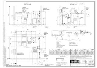
Sample Layout sketch
1x SX with exhaust air fan
This drawing also contains work to be done on site. The regulations of EN 1012 & VDE 0100 have to be
observed; the requirements of existing operational safety ordinance and the manuals have to be considered
by the operator and the employer respectively at the place of installation.
The national safety and accident prevention regulations have to be observed.
The installation of a sub- assembly in terms of the pressure equipment directive 97/23/EC has to be carried
out according to this directive.
A A
SECTION A-A
B
B
SECTION B-B
800 627 600 500
600590
200
1500484
300630
222
970
1582
747
970
747
2800
3100
2300
Louvre for Incoming air
package controlled with
weather protective lattice
Screw
compressor
Air
receiver
Centrifugal
separator with
ECO- Drain
Refrigeration
dryer
Air main
charging
system
Microfilter-
activated carbon
combination
Condensate
treatment unit
AQUAMAT
Pressure
line
Condensate lines have to be connected
to a collecting line via swan neck or are
to be fed to the oil/water separator
separately. A pressure-less drain has
to be provided for.
Ambient temperature
min.: + 3° C
max.: + 40° C
Condensate
line
To the
mains
ATTENTION!
Minimum width of door is total width of unit + 100 mm
Centrifugal
separator with
ECO- Drain
Screw
compressor
Condensate
treatment unit
AQUAMAT
Screw
compressor
Air exhaust fan
temperature controlled
Air main
charging
system
Louvre for Incoming air
package controlled with
weather protective lattice
Refrigeration
dryer
Refrigeration
dryer
Microfilter-
activated carbon
combination
To the
mains
** Designed for reference terms
DIN/ ISO 7183 Option A
Compressor-
model
Compressed
air
connection
Air entrance
aperture m²
free cross
section per
unit
Incomming
air volume
m³/ h per
unit
Air exhaust
fan m³/ h
Centrifugal
separator
model
Compressed
air
connection
ECO-
DRAIN
Minimum air
receiver
capacity l
ECO-
DRAIN
Refrigeration-
dryer model
**
Compressed
air
connection
Air entrance
aperture m²
free cross
section per
unit
Incomming
air volume
m³/ h per
unit
Microfilter-
activated
carbon
combination
model
Compressed
air
connection
Condensate
treatment
unit
AQUAMAT
SX 3 G 3/4 0,2 1200 1200 ZK 01 G 3/4 31 150 31 TA 5 G 3/4 0,1 650 FFG 6- D R 3/8 CF 3
SX 4 G 3/4 0,2 1450 1450 ZK 01 G 3/4 31 150 31 TA 5 G 3/4 0,1 650 FFG 6- D R 3/8 CF 3
SX 6 G 3/4 0,2 1800 1800 ZK 01 G 3/4 31 250 31 TA 5 G 3/4 0,1 650 FFG 6- D R 3/8 CF 3
SX 8 G 3/4 0,2 2400 2400 ZK 01 G 3/4 31 250 31 TA 8 G 3/4 0,1 650 FFG 10- D R 3/8 CF 3
Safety codes on site have to be
paid attention to.
Condensate line
1
2 3 4 5
6
7
8
9
10
5
1
2
3
4
5
6
7
8
9
10
Screw compressor
Hose line
Centrifugal separator
Ball valve
Air receiver tank
Refrigeration dryer
Micofilter Activated Carbon combination
Automatic condensate drain
Condensate Treatmente unit
Air main charging system
Legend
*
*Bypass lines should
not be fitted on standby units
or when 100 % compressed air
quality is required.
The requirements of items 3 and 5 should
be chosen according operating conditions.
Water
Oil
To the
mains
p
i
Control line
Air exhaust fan
temperature controlledAir exhaust fan
temperature controlled
Air exhaust fan
temperature controlled
3. 800 897
400590
3500
2000
AA
B
B
A-A B-B
Oil
Water
1
2 3
4
6
7
8
To the
mains
Condensate main pipe
p
i
5
Screw compressor with integrated refrigeration dryer
Hose line
Ball valve
Microfilter- activated carbon combination
Pressure transducer
Air receiver
Air main charging system
Condensate treatment unit
1
2
3
4
5
6
7
8
Legend
Control line for external pressure transducer
970
1221
2500
Section Section
200
800 450O 100202
222
Compressor-
model
Compressed
air
connection
Air entrance
aperture m²
free cross
section per
unit
Incomming
air volume
m³/h per unit
Air exhaust
fan m³/h
Minimum air
receiver
capacity l
ECO- DRAIN
Microfilter-
activated
carbon
combination
model
Compressed
air
connection
Condensate
treatment
unit
AQUAMAT
SX 3 T G 3/4 0,2 1500 1500 150 31 FFG 6- D R 3/8 CF 3
SX 4 T G 3/4 0,2 1700 1700 150 31 FFG 6- D R 3/8 CF 3
SX 6 T G 3/4 0,2 2100 2100 150 31 FFG 6- D R 3/8 CF 3
SX 8 T G 3/4 0,25 2600 2600 150 31 FFG 10- D R 1/2 CF 3
Air exhaust fan
thermostatically
controlled
Louvre for incoming air
package controlled
with weather protective
lattice
ATTENTION!
Minimum width of door is total width of unit + 100 mm
Safety codes on site have to be
paid attention to.
Condensate lines have to be connected
to a collecting line via swan neck or are
to be fed to the oil/water separator
separately. A pressure-less drain has
to be provided for.
Ambient temperature
min.: + 3° C
max.: + 40° C
Screw
compressor
Screw
compressor
Screw
compressor
Condensate
main pipe
Condensate
treatment unit
AQUAMAT
Condensate
treatment unit
AQUAMAT
Air receiver
Air main
charging
system
Microfilter-
activated
carbon
combination
DieZeichnungbleibtunserausschließlichesEigentum.SiewirdnurzudemvereinbartenZweckanvertrautunddarfzukeinem
anderenZweckverwendetwerden.KopienodersonstigeVervielfältigungeneinschließlichSpeicherung,Verarbeitungoder
VerbreitungunterVerwendungelektronischerSystemedürfennurzudemvereinbartenZweckangefertigtwerden.Weder
OriginalnochVervielfältigungendürfenDrittenausgehändigtoderinsonstigerWeisezugänglichgemachtwerden.
Drawingsremainourexclusiveproperty.Theyareentrustedonlyfortheagreedpurpose.Copiesoranyotherreproduction,
includingstorage,treatmentanddisseminationbyuseofelectronicsystemsmustnotbemadeforanyotherthantheagreed
purpose.Neitheroriginalsnorreproductionsmaybegiventoormadeavailabletothirdparties.
We reserve the right to make changes in the course of developement. This drawing can only be modified with CAD
Page
Plan No.Name
NameScale
Inst.
Checked
Drawn
P + I Date
X
X
1:20 01.12.2009
01.12.2009
blinzler1
Ernst
LYMU0003600e
1 of 2
Sample layout sketch
1x SX T with exhaust air fan
This drawing also contains work to be done on site. The regulations of EN 1012 & VDE 0100 have to be
observed; the requirements of existing operational safety ordinance and the manuals have to be considered
by the operator and the employer respectively at the place of installation.
The national safety and accident prevention regulations have to be observed.
The installation of a sub- assembly in terms of the pressure equipment directive 97/23/EC has to be carried
out according to this directive.
4. Ambient temperature
min.: + 3° C
max.: + 40° C
ATTENTION!
Minimum width of door is total width of unit + 100 mm
Safety codes on site have to be
paid attention to.
Condensate lines have to be connected
to a collecting line via swan neck or are
to be fed to the oil/water separator
separately. A pressure-less drain has
to be provided for.
DieZeichnungbleibtunserausschließlichesEigentum.SiewirdnurzudemvereinbartenZweckanvertrautunddarfzukeinem
anderenZweckverwendetwerden.KopienodersonstigeVervielfältigungeneinschließlichSpeicherung,Verarbeitungoder
VerbreitungunterVerwendungelektronischerSystemedürfennurzudemvereinbartenZweckangefertigtwerden.Weder
OriginalnochVervielfältigungendürfenDrittenausgehändigtoderinsonstigerWeisezugänglichgemachtwerden.
Drawingsremainourexclusiveproperty.Theyareentrustedonlyfortheagreedpurpose.Copiesoranyotherreproduction,
includingstorage,treatmentanddisseminationbyuseofelectronicsystemsmustnotbemadeforanyotherthantheagreed
purpose.Neitheroriginalsnorreproductionsmaybegiventoormadeavailabletothirdparties.
We reserve the right to make changes in the course of developement. This drawing can only be modified with CAD
Page
Plan No.Name
NameScale
Inst.
Checked
Drawn
P + I Date
X
X
1:20 01.12.2009
01.12.2009
blinzler1
Ernst
LYMU0003600e
2 of 2
Sample layout sketch
1x SX T with exhaust air fan
This drawing also contains work to be done on site. The regulations of EN 1012 & VDE 0100 have to be
observed; the requirements of existing operational safety ordinance and the manuals have to be considered
by the operator and the employer respectively at the place of installation.
The national safety and accident prevention regulations have to be observed.
The installation of a sub- assembly in terms of the pressure equipment directive 97/23/EC has to be carried
out according to this directive.
5. 2800
4000
AA
B
B
A-A B-B
1221
Section Section
200
450O
100
202
222
Air exhaust fan
thermostatically
controlled
Louvre for incoming air
package controlled
with weather protective
lattice
ATTENTION!
Minimum width of door is total width of unit + 100 mm
Safety codes on site have to be
paid attention to.
Condensate lines have to be connected
to a collecting line via swan neck or are
to be fed to the oil/water separator
separately. A pressure-less drain has
to be provided for.
Ambient temperature
min.: + 3° C
max.: + 40° C
Screw
compressor
Screw
compressor
Condensate
main pipe
Condensate
treatment unit
AQUAMAT
Condensate
treatment unit
AQUAMAT
Air receiver
Oil
Water
1
2
3
4
8
To the
mains
Condensate main pipe
Screw compressor with integrated refrigeration dryer
Hose line
Ball valve
Microfilter Activated carbon combination
Pressure transducer
Air receiver tank
Air main charging system
Condensate treatment unit
Control
1
2
3
4
5
6
7
8
9
Legend
Control line
1
2 3
4
6
7p
i
5
9
SAM SAM
Screw
compressor
Air receiver
Compressor-
model
Compressed
air
connection
Air entrance
aperture m²
free cross
section per
unit
Incomming
air volume
m³/h per unit
Air exhaust
fan m³/h
Minimum air
receiver
capacity l
ECO- DRAIN
Microfilter-
activated
carbon
combination
model
Compressed
air
connection
Condensate
treatment
unit
AQUAMAT
SX 3 T G 3/4 0,2 1500 3000 150 31 FFG 6- D R 3/8 CF 3
SX 4 T G 3/4 0,2 1700 3400 150 31 FFG 6- D R 3/8 CF 3
SX 6 T G 3/4 0,2 2100 4200 150 31 FFG 6- D R 3/8 CF 3
SX 8 T G 3/4 0,25 2600 5200 150 31 FFG 10- D R 1/2 CF 3
To the
mains
Air main
charging
system
SAM
600 590
500
Screw
compressor
500897800897
Louvre for incoming air
package controlled
with weather protective
lattice
Screw
compressor
970
2500
Microfilter-
activated carbon
combination
Microfilter-
activated carbon
combination
Microfilter-
activated carbon
combination
DieZeichnungbleibtunserausschließlichesEigentum.SiewirdnurzudemvereinbartenZweckanvertrautunddarfzukeinem
anderenZweckverwendetwerden.KopienodersonstigeVervielfältigungeneinschließlichSpeicherung,Verarbeitungoder
VerbreitungunterVerwendungelektronischerSystemedürfennurzudemvereinbartenZweckangefertigtwerden.Weder
OriginalnochVervielfältigungendürfenDrittenausgehändigtoderinsonstigerWeisezugänglichgemachtwerden.
Drawingsremainourexclusiveproperty.Theyareentrustedonlyfortheagreedpurpose.Copiesoranyotherreproduction,
includingstorage,treatmentanddisseminationbyuseofelectronicsystemsmustnotbemadeforanyotherthantheagreed
purpose.Neitheroriginalsnorreproductionsmaybegiventoormadeavailabletothirdparties.
We reserve the right to make changes in the course of developement. This drawing can only be modified with CAD
Page
Plan No.Name
NameScale
Inst.
Checked
Drawn
P + I Date
X
X
1:20 19.03.2010
19.03.2010
blinzler1
Jeske
LYMU0003800e
1 of 2
Sample layout sketch
2x SX T with exhaust air fan
This drawing also contains work to be done on site. The regulations of EN 1012 & VDE 0100 have to be
observed; the requirements of existing operational safety ordinance and the manuals have to be considered
by the operator and the employer respectively at the place of installation.
The national safety and accident prevention regulations have to be observed.
The installation of a sub- assembly in terms of the pressure equipment directive 97/23/EC has to be carried
out according to this directive.
6. Ambient temperature
min.: + 3° C
max.: + 40° C
ATTENTION!
Minimum width of door is total width of unit + 100 mm
Safety codes on site have to be
paid attention to.
Condensate lines have to be connected
to a collecting line via swan neck or are
to be fed to the oil/water separator
separately. A pressure-less drain has
to be provided for.
DieZeichnungbleibtunserausschließlichesEigentum.SiewirdnurzudemvereinbartenZweckanvertrautunddarfzukeinem
anderenZweckverwendetwerden.KopienodersonstigeVervielfältigungeneinschließlichSpeicherung,Verarbeitungoder
VerbreitungunterVerwendungelektronischerSystemedürfennurzudemvereinbartenZweckangefertigtwerden.Weder
OriginalnochVervielfältigungendürfenDrittenausgehändigtoderinsonstigerWeisezugänglichgemachtwerden.
Drawingsremainourexclusiveproperty.Theyareentrustedonlyfortheagreedpurpose.Copiesoranyotherreproduction,
includingstorage,treatmentanddisseminationbyuseofelectronicsystemsmustnotbemadeforanyotherthantheagreed
purpose.Neitheroriginalsnorreproductionsmaybegiventoormadeavailabletothirdparties.
We reserve the right to make changes in the course of developement. This drawing can only be modified with CAD
Page
Plan No.Name
NameScale
Inst.
Checked
Drawn
P + I Date
X
X
1:20 19.03.2010
19.03.2010
blinzler1
Jeske
LYMU0003800e
2 of 2
Sample layout sketch
2x SX T with exhaust air fan
This drawing also contains work to be done on site. The regulations of EN 1012 & VDE 0100 have to be
observed; the requirements of existing operational safety ordinance and the manuals have to be considered
by the operator and the employer respectively at the place of installation.
The national safety and accident prevention regulations have to be observed.
The installation of a sub- assembly in terms of the pressure equipment directive 97/23/EC has to be carried
out according to this directive.
7. DieZeichnungbleibtunserausschließlichesEigentum.SiewirdnurzudemvereinbartenZweckanvertrautunddarfzukeinem
anderenZweckverwendetwerden.KopienodersonstigeVervielfältigungeneinschließlichSpeicherung,Verarbeitungoder
VerbreitungunterVerwendungelektronischerSystemedürfennurzudemvereinbartenZweckangefertigtwerden.Weder
OriginalnochVervielfältigungendürfenDrittenausgehändigtoderinsonstigerWeisezugänglichgemachtwerden.
Drawingsremainourexclusiveproperty.Theyareentrustedonlyfortheagreedpurpose.Copiesoranyotherreproduction,
includingstorage,treatmentanddisseminationbyuseofelectronicsystemsmustnotbemadeforanyotherthantheagreed
purpose.Neitheroriginalsnorreproductionsmaybegiventoormadeavailabletothirdparties.
We reserve the right to make changes in the course of developement. This drawing can only be modified with CAD
Page
Plan No.Name
NameScale
Inst.
Checked
Drawn
P + I Date
X
X
1:20 01.03.2011
01.03.2011
Langgu1
Ernst
LYMU0003100e
3 of 4
Sample Layout sketch
1x SX with exhaust duct
This drawing also contains work to be done on site. The regulations of EN 1012 & VDE 0100 have to be
observed; the requirements of existing operational safety ordinance and the manuals have to be considered
by the operator and the employer respectively at the place of installation.
The national safety and accident prevention regulations have to be observed.
The installation of a sub- assembly in terms of the pressure equipment directive 97/23/EC has to be carried
out according to this directive.
A A
SECTION A-A
B
B
SECTION B-B
800 627 600 500
600590
200
1500484
300630
222
970
1582
747
970
747
2800
3100
2300
Louvre for Incoming air
package controlled with
weather protective lattice
Screw
compressor
Air
receiver
Centrifugal
separator with
ECO- Drain
Refrigeration
dryer
Air main
charging
system
Microfilter-
activated carbon
combination
Condensate
treatment unit
AQUAMAT
Pressure
line
Condensate lines have to be connected
to a collecting line via swan neck or are
to be fed to the oil/water separator
separately. A pressure-less drain has
to be provided for.
Ambient temperature
min.: + 3° C
max.: + 40° C
Condensate
line
To the
mains
ATTENTION!
Minimum width of door is total width of unit + 100 mm
Centrifugal
separator with
ECO- Drain
Screw
compressor
Condensate
treatment unit
AQUAMAT
Screw
compressor
Air exhaust fan
temperature controlled
Air main
charging
system
Louvre for Incoming air
package controlled with
weather protective lattice
Refrigeration
dryer
Refrigeration
dryer
Microfilter-
activated carbon
combination
To the
mains
** Designed for reference terms
DIN/ ISO 7183 Option A
Air exhaust fan
temperature controlled
Safety codes on site have to be
paid attention to.
Recirculating air louvre
thermostatically controlled
Recirculating air louvre
thermostatically controlled
Louvre for outgoing air
thermostatically controlled with
weather protective lattice
Louvre for outgoing air
thermostatically controlled with
weather protective lattice
Compressor-
model
Compressed
air
connection
Air entrance
aperture m²
free cross
section per
unit
Incomming
air volume
m³/ h per
unit
Air exhaust
duct
dimensions
mm
Centrifugal
separator
model
Compressed
air
connection
ECO-
DRAIN
Minimum air
receiver
capacity l
ECO-
DRAIN
Refrigeration-
dryer model
**
Compressed
air
connection
Air entrance
aperture m²
free cross
section per
unit
Incomming
air volume
m³/ h per
unit
Microfilter-
activated
carbon
combination
model
Compressed
air
connection
Condensate
treatment
unit
AQUAMAT
SX 3 G 3/4 0,2 1050 500 X 250 ZK 01 G 3/4 31 150 31 TA 5 G 3/4 0,1 650 FFG 6- D R 3/8 CF 3
SX 4 G 3/4 0,2 1050 500 X 250 ZK 01 G 3/4 31 150 31 TA 5 G 3/4 0,1 650 FFG 6- D R 3/8 CF 3
SX 6 G 3/4 0,2 1050 500 X 250 ZK 01 G 3/4 31 250 31 TA 5 G 3/4 0,1 650 FFG 6- D R 3/8 CF 3
SX 8 G 3/4 0,2 1350 500 X 250 ZK 01 G 3/4 31 250 31 TA 8 G 3/4 0,1 650 FFG 10- D R 1/2 CF 3
Condensate line
1
2 3 4
5
6
7
8
9
10
5
1
2
3
4
5
6
7
8
9
10
Screw compressor
Hose line
Centrifugal separator
Ball valve
Air receiver tank
Refrigeration dryer
Micofilter Activated Carbon combination
Automatic condensate drain
Condensate Treatmente unit
Air main charging system
Legend
*
*Bypass lines should
not be fitted on standby units
or when 100 % compressed air
quality is required.
The requirements of items 3 and 5 should
be chosen according operating conditions.
Water
Oil
To the
mains
p
i
Control line
9. 800 897
400590
3500
2000
AA
B
B
A-A B-B
Oil
Water
1
2 3
4
6
7
8
To the
mains
Condensate main pipe
p
i
5
Screw compressor with integrated refrigeration dryer
Hose line
Ball valve
Microfilter- activated carbon combination
Pressure transducer
Air receiver
Air main charging system
Condensate treatment unit
1
2
3
4
5
6
7
8
Legend
Control line for external pressure transducer
970
1221
2500
Section Section
200
800 450O 100202
222
Air exhaust fan
thermostatically
controlled
Louvre for incoming air
package controlled
with weather protective
lattice
ATTENTION!
Minimum width of door is total width of unit + 100 mm
Safety codes on site have to be
paid attention to.
Condensate lines have to be connected
to a collecting line via swan neck or are
to be fed to the oil/water separator
separately. A pressure-less drain has
to be provided for.
Ambient temperature
min.: + 3° C
max.: + 40° C
Screw
compressor
Screw
compressor
Screw
compressor
Condensate
main pipe
Condensate
treatment unit
AQUAMAT
Condensate
treatment unit
AQUAMAT
Air receiver
Air main
charging
system
Microfilter-
activated
carbon
combination
DieZeichnungbleibtunserausschließlichesEigentum.SiewirdnurzudemvereinbartenZweckanvertrautunddarfzukeinem
anderenZweckverwendetwerden.KopienodersonstigeVervielfältigungeneinschließlichSpeicherung,Verarbeitungoder
VerbreitungunterVerwendungelektronischerSystemedürfennurzudemvereinbartenZweckangefertigtwerden.Weder
OriginalnochVervielfältigungendürfenDrittenausgehändigtoderinsonstigerWeisezugänglichgemachtwerden.
Drawingsremainourexclusiveproperty.Theyareentrustedonlyfortheagreedpurpose.Copiesoranyotherreproduction,
includingstorage,treatmentanddisseminationbyuseofelectronicsystemsmustnotbemadeforanyotherthantheagreed
purpose.Neitheroriginalsnorreproductionsmaybegiventoormadeavailabletothirdparties.
We reserve the right to make changes in the course of developement. This drawing can only be modified with CAD
Page
Plan No.Name
NameScale
Inst.
Checked
Drawn
P + I Date
X
X
1:20 01.12.2009
01.12.2009
blinzler1
Ernst
LYMU0003700e
1 of 2
Sample layout sketch
1x SX T with exhaust air duct
This drawing also contains work to be done on site. The regulations of EN 1012 & VDE 0100 have to be
observed; the requirements of existing operational safety ordinance and the manuals have to be considered
by the operator and the employer respectively at the place of installation.
The national safety and accident prevention regulations have to be observed.
The installation of a sub- assembly in terms of the pressure equipment directive 97/23/EC has to be carried
out according to this directive.
Louvre for outgoing air
thermostatically controlled with
weather protective lattice
Louvre for recirculation air
thermostatically controlled
Compressor-
model
Compressed
air
connection
Air entrance
aperture m²
free cross
section per
unit
Incomming
air volume
m³/h per unit
Air exhaust
duct
dimensions
mm
Permissible
overall pressure
loss for
exhaust air
duct ∆p
Exhaust air
fan for each
dryer m³/h
Minimum air
receiver
capacity l
ECO- DRAIN
Microfilter-
activated
carbon
combination
model
Compressed
air
connection
Condensate
treatment
unit
AQUAMAT
SX 3 T G 3/4 0,2 1500 500 X 150 30 540 150 31 FFG 6- D R 3/8 CF 3
SX 4 T G 3/4 0,2 1500 500 X 150 30 540 150 31 FFG 6- D R 3/8 CF 3
SX 6 T G 3/4 0,2 1700 500 X 150 30 780 150 31 FFG 6- D R 3/8 CF 3
SX 8 T G 3/4 0,25 2000 500 X 150 30 780 150 31 FFG 10- D R 1/2 CF 3
To the
mains
10. Ambient temperature
min.: + 3° C
max.: + 40° C
ATTENTION!
Minimum width of door is total width of unit + 100 mm
Safety codes on site have to be
paid attention to.
Condensate lines have to be connected
to a collecting line via swan neck or are
to be fed to the oil/water separator
separately. A pressure-less drain has
to be provided for.
DieZeichnungbleibtunserausschließlichesEigentum.SiewirdnurzudemvereinbartenZweckanvertrautunddarfzukeinem
anderenZweckverwendetwerden.KopienodersonstigeVervielfältigungeneinschließlichSpeicherung,Verarbeitungoder
VerbreitungunterVerwendungelektronischerSystemedürfennurzudemvereinbartenZweckangefertigtwerden.Weder
OriginalnochVervielfältigungendürfenDrittenausgehändigtoderinsonstigerWeisezugänglichgemachtwerden.
Drawingsremainourexclusiveproperty.Theyareentrustedonlyfortheagreedpurpose.Copiesoranyotherreproduction,
includingstorage,treatmentanddisseminationbyuseofelectronicsystemsmustnotbemadeforanyotherthantheagreed
purpose.Neitheroriginalsnorreproductionsmaybegiventoormadeavailabletothirdparties.
We reserve the right to make changes in the course of developement. This drawing can only be modified with CAD
Page
Plan No.Name
NameScale
Inst.
Checked
Drawn
P + I Date
X
X
1:20 01.12.2009
01.12.2009
blinzler1
Ernst
LYMU0003700e
2 of 2
Sample layout sketch
1x SX T with exhaust air duct
This drawing also contains work to be done on site. The regulations of EN 1012 & VDE 0100 have to be
observed; the requirements of existing operational safety ordinance and the manuals have to be considered
by the operator and the employer respectively at the place of installation.
The national safety and accident prevention regulations have to be observed.
The installation of a sub- assembly in terms of the pressure equipment directive 97/23/EC has to be carried
out according to this directive.
11. 2800
4000
AA
B
B
A-A B-B
1221
Section Section
200
450O
100
202
222
Air exhaust fan
thermostatically
controlled
Louvre for incoming air
package controlled
with weather protective
lattice
ATTENTION!
Minimum width of door is total width of unit + 100 mm
Safety codes on site have to be
paid attention to.
Condensate lines have to be connected
to a collecting line via swan neck or are
to be fed to the oil/water separator
separately. A pressure-less drain has
to be provided for.
Ambient temperature
min.: + 3° C
max.: + 40° C
Screw
compressor
Screw
compressor
Condensate
main pipe
Condensate
treatment unit
AQUAMAT
Condensate
treatment unit
AQUAMAT
Air receiver
Oil
Water
1
2
3
4
8
To the
mains
Condensate main pipe
Screw compressor with integrated refrigeration dryer
Hose line
Ball valve
Microfilter Activated carbon combination
Pressure transducer
Air receiver tank
Air main charging system
Condensate treatment unit
Control
1
2
3
4
5
6
7
8
9
Legend
Control line
1
2 3
4
6
7p
i
5
9
SAM SAM
Screw
compressor
Air receiver
To the
mains
Air main
charging
system
SAM
600 590
500
Screw
compressor
500897800897
Louvre for incoming air
package controlled
with weather protective
lattice
Screw
compressor
970
2500
Microfilter-
activated carbon
combination
Louvre for outgoing air
thermostatically controlled
with weather protective
lattice
Recirculating air louvre
thermostatically controlled
Compressor-
model
Compressed
air
connection
Air entrance
aperture m²
free cross
section per
unit
Incomming
air volume
m³/h per unit
Air exhaust
duct
dimensions
mm
Permissible
overall
pressure loss
for exhaust air
duct ∆p
Exhaust air
fan for each
dryer m³/h
Minimum air
receiver
capacity l
ECO- DRAIN
Microfilter-
activated
carbon
combination
model
Compressed
air
connection
Condensate
treatment
unit
AQUAMAT
SX 3 T G 3/4 0,2 1500 500 X 150 30 540 150 31 FFG 6- D R 3/8 CF 3
SX 4 T G 3/4 0,2 1500 500 X 150 30 540 150 31 FFG 6- D R 3/8 CF 3
SX 6 T G 3/4 0,2 1700 500 X 150 30 780 150 31 FFG 6- D R 3/8 CF 3
SX 8 T G 3/4 0,25 2000 500 X 150 30 780 150 31 FFG 10- D R 1/2 CF 3
DieZeichnungbleibtunserausschließlichesEigentum.SiewirdnurzudemvereinbartenZweckanvertrautunddarfzukeinem
anderenZweckverwendetwerden.KopienodersonstigeVervielfältigungeneinschließlichSpeicherung,Verarbeitungoder
VerbreitungunterVerwendungelektronischerSystemedürfennurzudemvereinbartenZweckangefertigtwerden.Weder
OriginalnochVervielfältigungendürfenDrittenausgehändigtoderinsonstigerWeisezugänglichgemachtwerden.
Drawingsremainourexclusiveproperty.Theyareentrustedonlyfortheagreedpurpose.Copiesoranyotherreproduction,
includingstorage,treatmentanddisseminationbyuseofelectronicsystemsmustnotbemadeforanyotherthantheagreed
purpose.Neitheroriginalsnorreproductionsmaybegiventoormadeavailabletothirdparties.
We reserve the right to make changes in the course of developement. This drawing can only be modified with CAD
Page
Plan No.Name
NameScale
Inst.
Checked
Drawn
P + I Date
X
X
1:20 19.03.2010
19.03.2010
blinzler1
Jeske
LYMU0003900e
1 of 2
Sample layout sketch
2x SX T with exhaust air duct
This drawing also contains work to be done on site. The regulations of EN 1012 & VDE 0100 have to be
observed; the requirements of existing operational safety ordinance and the manuals have to be considered
by the operator and the employer respectively at the place of installation.
The national safety and accident prevention regulations have to be observed.
The installation of a sub- assembly in terms of the pressure equipment directive 97/23/EC has to be carried
out according to this directive.
12. Ambient temperature
min.: + 3° C
max.: + 40° C
ATTENTION!
Minimum width of door is total width of unit + 100 mm
Safety codes on site have to be
paid attention to.
Condensate lines have to be connected
to a collecting line via swan neck or are
to be fed to the oil/water separator
separately. A pressure-less drain has
to be provided for.
DieZeichnungbleibtunserausschließlichesEigentum.SiewirdnurzudemvereinbartenZweckanvertrautunddarfzukeinem
anderenZweckverwendetwerden.KopienodersonstigeVervielfältigungeneinschließlichSpeicherung,Verarbeitungoder
VerbreitungunterVerwendungelektronischerSystemedürfennurzudemvereinbartenZweckangefertigtwerden.Weder
OriginalnochVervielfältigungendürfenDrittenausgehändigtoderinsonstigerWeisezugänglichgemachtwerden.
Drawingsremainourexclusiveproperty.Theyareentrustedonlyfortheagreedpurpose.Copiesoranyotherreproduction,
includingstorage,treatmentanddisseminationbyuseofelectronicsystemsmustnotbemadeforanyotherthantheagreed
purpose.Neitheroriginalsnorreproductionsmaybegiventoormadeavailabletothirdparties.
We reserve the right to make changes in the course of developement. This drawing can only be modified with CAD
Page
Plan No.Name
NameScale
Inst.
Checked
Drawn
P + I Date
X
X
1:20 19.03.2010
19.03.2010
blinzler1
Jeske
LYMU0003900e
2 of 2
Sample layout sketch
2x SX T with exhaust air duct
This drawing also contains work to be done on site. The regulations of EN 1012 & VDE 0100 have to be
observed; the requirements of existing operational safety ordinance and the manuals have to be considered
by the operator and the employer respectively at the place of installation.
The national safety and accident prevention regulations have to be observed.
The installation of a sub- assembly in terms of the pressure equipment directive 97/23/EC has to be carried
out according to this directive.