Weitere ähnliche Inhalte
Ähnlich wie Ac aquaero 4.00_20071105engl
Ähnlich wie Ac aquaero 4.00_20071105engl (20)
Ac aquaero 4.00_20071105engl
- 1. MANUAL
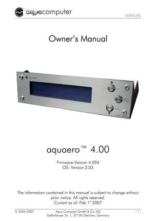
Owner’s Manual
aquaero™ 4.00
Firmware-Version 4.09d
OS- Version 2.03
The information contained in this manual is subject to change without
prior notice. All rights reserved.
Current as of: Feb 1st 2007
© 2004-2007 Aqua Computer GmbH & Co. KG -1-
Gelliehäuser Str. 1, 37130 Gleichen, Germany
- 2. AQUAERO
Table of Contents
1. Contents of the package ...................................................6
2. Preface............................................................................6
3. Safety precautions ............................................................7
4. Connecting external components.......................................8
4.1. Overview..................................................................................... 8
4.2. Power ......................................................................................... 8
4.3. Fan1-Fan4 .................................................................................. 8
4.4. Sensor ........................................................................................ 8
4.5. Flow ........................................................................................... 9
4.6. USB ............................................................................................ 9
4.7. LED .......................................................................................... 10
4.8. Relay ........................................................................................ 10
4.9. aquastream-bridge..................................................................... 10
4.10. Standby-Power......................................................................... 11
4.11. JP1 Power Supply Jumper.......................................................... 11
4.12. aquabus (I2C-bus) .................................................................... 11
4.13. Expansion................................................................................ 11
4.14. Power-LED............................................................................... 11
4.15. Aquaero Power Connect (optional accessory).............................. 12
5. Initial operation..............................................................13
6. Display and Operation ...................................................14
6.1. Function of the Buttons ............................................................... 14
6.2. Display Mode ............................................................................ 14
7. Device Settings...............................................................17
7.1. Basic operation.......................................................................... 17
7.1.1. Definition of Names.......................................................................... 17
7.1.2. Principle of assigning sensors to fans .................................................. 17
7.2. Menu Settings ............................................................................ 18
7.2.1. Sensor-Parameters........................................................................ 18
7.3.2. Flow Sensor ................................................................................. 18
7.3.3. Fan-Parameters............................................................................ 18
7.3.4. Display-Parameters....................................................................... 18
7.3.5. Relay-Parameters.......................................................................... 18
7.3.6. LED-Parameters ........................................................................... 18
7.3.7. Clock and Timer .......................................................................... 19
7.3.8. Periph.-Parameters ....................................................................... 19
7.3.9. Power measurement.......................................................................... 19
7.3.10. Profile settings ................................................................................ 19
-2- Aqua Computer GmbH & Co. KG © 2004-2007
Gelliehäuser Str. 1, 37130 Gleichen, Germany
- 3. MANUAL
7.3.11. Return to Display ............................................................................ 19
8. Menu „Sensor-Parameters“ .............................................20
8.1. Sensor Name............................................................................. 20
8.2. Start-up temp............................................................................. 20
8.3. Maximum temp.......................................................................... 20
8.4. Alarm Temp............................................................................... 20
8.5. Hysteresis .................................................................................. 20
8.6. Target Temp. ............................................................................. 21
8.7. Calibration Offset ...................................................................... 21
8.8. Calibration Factor ...................................................................... 21
8.9. Controller delay ......................................................................... 22
8.10. Controller factor ...................................................................... 22
8.11. Back ....................................................................................... 22
9. Menu „Flow Sensor“.......................................................23
9.1. Sensor name ............................................................................. 23
9.2. Alarm Level 1 ............................................................................ 23
9.3. Alarm Level 2 ............................................................................ 23
9.4. Display Unit............................................................................... 23
9.5. Calibration Factor ...................................................................... 23
9.6. Sensor 2 Connection .................................................................. 23
9.7. Back ......................................................................................... 24
10. Menu "Fan Parameters".................................................25
10.1. Fan Name............................................................................... 25
10.2. Sensor 1 (auto) ........................................................................ 25
10.3. Sensor 2 (auto) ........................................................................ 25
10.4. Set Rpm .................................................................................. 25
10.5. Manual ................................................................................... 26
10.6. Get max. rpm .......................................................................... 26
10.7. Calibration Factor .................................................................... 26
10.8. Minimum Power ....................................................................... 26
10.9. Control Options....................................................................... 27
10.10. Use rpm signal....................................................................... 27
10.11. Hold min. power .................................................................... 28
10.12. Back ..................................................................................... 28
11. Menu "Display Parameters"............................................29
11.1. Brightness................................................................................ 29
11.2. Contrast .................................................................................. 29
11.3. Turn-off Time........................................................................... 29
11.4. Switch Time ............................................................................. 29
11.5. LCD switch-off ......................................................................... 29
11.6. USBLCD-Mode ........................................................................ 29
© 2004-2007 Aqua Computer GmbH & Co. KG -3-
Gelliehäuser Str. 1, 37130 Gleichen, Germany
- 4. AQUAERO
11.7. USBLCD after Boot................................................................... 29
11.8. Aquaero-Name........................................................................ 30
11.9. Page Setup .............................................................................. 30
11.10. Back ..................................................................................... 31
12. Menu "Relay Parameters"...............................................32
12.1. Alarm On/Off.......................................................................... 32
12.2. Alarm-Off-Timeout ................................................................... 32
12.3. Alarm-Events ........................................................................... 32
12.4. Relay On/Off........................................................................... 33
12.5. Relay Usage ............................................................................ 33
12.6. Alarm Time.............................................................................. 33
12.7. Back ....................................................................................... 33
13. Menu "LED Parameters".................................................34
13.1. Sensor 1 (auto) ........................................................................ 34
13.2. Sensor 2 (auto) ........................................................................ 34
13.3. Brighter/Darker ........................................................................ 34
13.4. Brightness................................................................................ 34
13.5. Flash when Alarm..................................................................... 35
13.6. Back ....................................................................................... 35
14. Menu "Clock and Timer" ...............................................36
14.1. Setting the Clock...................................................................... 36
14.2. Turn-On Time 1....................................................................... 36
14.3. On-Time 1 .............................................................................. 36
14.4. Turn-On Time 2....................................................................... 36
14.5. On-Time 2 .............................................................................. 36
14.6. Turn Off Time 1 ....................................................................... 36
14.7. Off-Time 1 .............................................................................. 37
14.8. Turn Off Time 2 ....................................................................... 37
14.9. Off-Time 2 .............................................................................. 37
14.10. Back ..................................................................................... 37
15. Menu "Periph.-Parameters" ............................................38
15.1. aquastream 1/2....................................................................... 38
15.2. Multiswitch 1/2 ........................................................................ 38
15.3. tubemeter................................................................................ 39
15.4. Back ....................................................................................... 39
16.1. Power Measurement 1 Sensor 1 (cold side) ................................. 40
16.2. Power Measurement 1 Sensor 2 (warm side) ............................... 40
16.3. Power Measurement 1 Flow Sensor Selection .............................. 40
16.4. Power Measurement 2 Sensor 1 (cold side) ................................. 41
16.5. Power Measurement 2 Sensor 2 (warm side) ............................... 41
16.6. Power Measurement 1 Flow Sensor Selection .............................. 41
-4- Aqua Computer GmbH & Co. KG © 2004-2007
Gelliehäuser Str. 1, 37130 Gleichen, Germany
- 5. MANUAL
16.7. Back ....................................................................................... 41
Leaves the submenu and returns to "Settings"........................................ 41
17. Menu „Profile Settings“ .................................................42
17.1. Load Profile 1 .......................................................................... 42
17.2. Load Profile 2 .......................................................................... 42
17.3. Copy Profile............................................................................. 42
17.4. Default Setting ......................................................................... 42
18. Example configurations.................................................43
18.1. Progressive Regulation of a Fan via a Temperature Sensor ........... 43
18.2. Regulation of a constant water temperature in a water-cooling system
....................................................................................................... 43
18.3. Temperature-dependent Illumination .......................................... 44
18.4. Emergency Shutdown of the PC at a Temperature Alarm .............. 45
19. Special Notices ............................................................45
19.1. Usage of the Relay as a Power Button on the mainboard.............. 45
19.2. Usage of the Relay to Interrupt the ATX-control-line...................... 46
19.3. Starting of the PC when using the Standby-Power-Supply.............. 46
19.4. Restrictions of the Emergency Shutdown...................................... 46
19.5. Flow Alarm and the aquastream-pump....................................... 46
19.6. Regulation of Contrast when Switching On ................................. 47
19.7. Changing the front plate ........................................................... 47
20. Troubleshooting ...........................................................48
20.1. Deletion of all Settings (EEPROM-Reset)...................................... 48
21. Technical Data.............................................................48
© 2004-2007 Aqua Computer GmbH & Co. KG -5-
Gelliehäuser Str. 1, 37130 Gleichen, Germany
- 6. AQUAERO
1. Contents of the package
1x aquaero (ready to install)
4x Temperature sensor 70 cm
1x internal USB-connection cable 5pin 70 cm
Mounting material
1x Software CD aquaero
1x this manual
2. Preface
customer,
Dear customer
We congratulate you on the purchase of an aquaero from May & Wille,
Aqua Computer Systeme GbR. We are one of the oldest manufacturers
in Germany of PC water-cooling systems. Our products are made from
materials of the highest quality. We hope you enjoy your new cooling
system. Should you have any questions, we would like to ask you to first
look at the "FAQ" area and "forum" on our homepage www.aqua-
computer.de. If you should not find an answer to your question there,
please email to support@aqua-computer.de. Considering the fast tech-
nical development, we reserve the right to be able to perform alterations
to the products at any time. It therefore is possible that your product
does not correspond precisely to the descriptions or especially the illus-
trations in this manual.
Your aqua-computer Team
-6- Aqua Computer GmbH & Co. KG © 2004-2007
Gelliehäuser Str. 1, 37130 Gleichen, Germany
- 7. MANUAL
3. Safety precautions
Before we get into the specifics of the system, we would like you to fol-
low these basic precautions which should be obeyed at all times.
1. Read this manual thoroughly and completely!
! 2. Backup your data before working on the hardware!
3. The aquaero may only be used completely assembled in a
! computer case!
! compo-
4. Never touch, connect or separate cables or electronic compo-
nents while in use!
! 5. Do not turn on your computer unless you are absolutely certain
that all cables are securely and correctly connected to the
! aquaero!
6. Maintenance notes: Use only soft, damp cloths to wipe the de- de-
! vice. Do not use benzene, paint thinner, detergents, or chemically
chemically
ob-
treated wiped cloths, and do not place vinyl, plastic, or rubber ob-
! jects on the device to avoid the risk of malfunction or damage to
surface of the device!
! relay-
7. The relay-output may be powered at max. 12 V! The current
must not exceed 1 Ampere!
! technologi-
8. All statements in this manual are subject to the fast technologi-
Techni-
cal development. Our products are constantly enhanced. Techni-
! cal changes, misprints and errors are reserved!
9. This product is not designed for use in life support appliances,
! systems
devices, or systems where malfunction of this product can rea- rea-
sonably be expected to result in personal injury. May & Wille GbR
! customers using or selling this product for use in such application
do so at their own risk and agree to fully indemnify May & Wille
! damages
GbR for any damages resulting from such application.
10. Do not rest your weight on or place heavy objects on the de-
de-
! vice, and do not apply excessive force to the buttons, switches, or
connectors to avoid the risk of damage to the device or personal
! injury.
© 2004-2007 Aqua Computer GmbH & Co. KG -7-
Gelliehäuser Str. 1, 37130 Gleichen, Germany
- 8. AQUAERO
4. Connecting external components
4.1. Overview
The following schematic shows the multitude of connection possibilities
of the aquaero:
4.2. Power
Power connector. Attach a vacant power connector of your PSU. Due to
the form of the plug the polarity can not be misinterpreted. Do not use
force when connecting the plug but double check if the plug is lined-up
correctly (i.e. not upside down)
4.3. Fan1-Fan4
Fan1-
Connection possibility for four fans with rpm-signals.
Attention: Max. load 5 Watts per channel!
Pin assignment: Pin 1: GND
Pin 2: 0-12 V
Pin 3: rpm
4.4. Sensor
Connection possibility for six temperature sensors (10 kΩ NTC).
Pin assignment: Pin 11-12: Sensor 1
Pin 9-10: Sensor 2
Pin 7-8: Sensor 3
Pin 5-6: Sensor 4
Pin 3-4: Sensor 5
Pin 1-2: Sensor 6
-8- Aqua Computer GmbH & Co. KG © 2004-2007
Gelliehäuser Str. 1, 37130 Gleichen, Germany
- 9. MANUAL
4.5. Flow
Connection possibility for a flow sensor. Only use flow sensors and ca-
bles specified by aqua-computer!
Pin assignment: Pin 1: GND (green cable, marked▼)
Pin 2: 5 V
Pin 3: Rpm
4.6. USB
Connection possibility for an internal USB-connector on the mainboard.
Use the included USB-cable and pay close attention to the polarity (col-
ored wires) of the cable. Incorrect use may result in the destruction of
the aquaero and/or the mainboard and further components! Therefore
components!
pay close attention to the pin assignment of the connectors on the
mainboard. Please consult the manual of your mainboard for help.
© 2004-2007 Aqua Computer GmbH & Co. KG -9-
Gelliehäuser Str. 1, 37130 Gleichen, Germany
- 10. AQUAERO
Pin assignment: Pin 1: GND black wire
Pin 2: GND black wire
Pin 3: D+ green wire
Pin 4: D- white wire
Pin 5: VCC red wire
4.7. LED
Connection possibility for two LEDs or one dual-colored LED (not in-
cluded in delivery) respectively. Standard-LEDs (I max 20 mA) may be
used without a series resistance, which is already integrated in the
aquaero.
Pin assignment: Pin 1: VCC LED 1
Pin 2: VCC LED 2
Pin 3: GND
4.8. Relay
Floating output. Useable for the emergency shutdown of the PSU (addi-
tional cables required, not included in delivery). Alternatively freely use-
able, maximum breaking capacity 1 A at max. 12 V.
Pin assignment: Pin 1-2: breaking contact
4.9. aquastream-bridge
aquastream-
Connection possibility to the controller of the aquastream. A maximum
of two controllers may be connected. Only use cables specified by
aqua-computer (not included in delivery)! The following table shows the
connection possibilities depending on the hardware revision of the aq-
uastream controller in use:
Revision Controller 1 Revision Controller 2
1.0 or higher Not possible
1.5 or higher 3.0 or higher
Attention: It is essential that, if the aquaero and the aquastream are
connected to each other, the power supply is connected to the aquaero
and to the aquastream controller.
- 10 - Aqua Computer GmbH & Co. KG © 2004-2007
Gelliehäuser Str. 1, 37130 Gleichen, Germany
- 11. MANUAL
Standby-
4.10. Standby-Power
Connection possibility for a additional power supply via the 5 V standby
strand of the PSU. In this case the aquaero stays active even when the
computer has been shut down (Soft-Off). See also JP1. Only use cables
specified by aqua-computer (not included in delivery)! See also 4.9.
Pin assignment: Pin 1: GND
Pin 2: +5V Standby
4.11. JP1 Power Supply Jumper
With this Jumper you can decide whether you would like the power sup-
ply coming from the power supply connector (see 4.2. Power) or the
standby-power supply (see 4.10. Standby-Power). By default the Jumper
is set for the power supply connector.
NOTICE: The supply of the fans and the display illumination are always
supplied via the power supply connector!
Jumper setting: Pin 1-2: Standard-power-supply
Pin 2-3: Standby-power-supply
4.12. aquabus (I2C-bus)
3-pin add-on connector for optional add-on components by aqua-
computer. Only use cables specified by aqua-computer (not included in
delivery)!
Pin assignment: Pin 1: GND
Pin 2: SDA
Pin 3: SCL
4.13. Expansion
20-pin expansion port for optional accessories from aqua-computer.
Only use cables and components specified by aqua-computer (not in-
cluded in delivery)!
Power-
4.14. Power-LED
This green LED shows the correct power supply to the microprocessor of
the aquaero. Should the LED not light up although the PSU is correctly
© 2004-2007 Aqua Computer GmbH & Co. KG - 11 -
Gelliehäuser Str. 1, 37130 Gleichen, Germany
- 12. AQUAERO
connected, please check the position of the jumper JP1. See 4.11. JP1
Power Supply Jumper.
4.15. Aquaero Power Connect (optional accessory)
The following picture shows the possible connections of the Aquaero
Power Connect cable. The standby power supply is to be connected to
the appropriate connector of the aquaero. The green ATX PS_ON# line
can be cut through and connected with a plug for the relay outlet. If you
want to use the relay outlet for connection to the power switch line of
the mainboard, the ATX PS_ON# line must remain intact!
- 12 - Aqua Computer GmbH & Co. KG © 2004-2007
Gelliehäuser Str. 1, 37130 Gleichen, Germany
- 13. MANUAL
5. Initial operation
After all connections to the aquaero have been made as described in
chapter 4 and the aquaero is installed in the computer case, you can
now operate it by switching on the computer.
After switching on of the computer, the aquaero will shows a greeting
screen with a statement of the firmware revision before it continues on to
the status of the fans and sensors.
You should now familiarize yourself with the functions and operating of
the device before you perform the setup of the basic settings in the
aquaero.
© 2004-2007 Aqua Computer GmbH & Co. KG - 13 -
Gelliehäuser Str. 1, 37130 Gleichen, Germany
- 14. AQUAERO
Operation
6. Display and Operation
6.1. Function of the Buttons
The aquaero uses three buttons to control the functions of the device.
The usage of the USB-connector and the included software is not neces-
sary but simplifies the operation.
Depending on the active display the buttons have the following func-
tions:
Button „up“: previous menu option/screen
increase chosen value
Button „down“: next menu option/screen
decrease chosen value
Button „set/mode“: Call menu
select menu
6.2. Display Mode
In the normal operation the time, fan, flow sensor and temperature sen-
sor screens are shown one after the other. The screen switches forward
or backward with each key press or, when the switch-time is active, after
the chosen interval.
You can add or remove single screens as well as define sensor names
freely, which is the reason why your screens may vary from the illustra-
tions in this manual.
Following screens will be shown one after the other:
aquaero v4.09d
So. 15:50:50
down up
Firmware: 4.09
Os: 2.03 LCD
down up
- 14 - Aqua Computer GmbH & Co. KG © 2004-2007
Gelliehäuser Str. 1, 37130 Gleichen, Germany
- 15. MANUAL
Hw. Rev.: 4.00
Serial: 999
down up
20,0C 20,0C 20,0C
20,0C 20,0C 20,0C
down up
Sensor 1 : 20,0C
Sensor 2 : 20,0C
down up
Sensor 3 : 20,0C
Sensor 4 : 20,0C
down up
Sensor 5 : 20,0C
Sensor 6 : 20,0C
down up
FAN1 100% FAN2 100%
FAN3 100% FAN4 100%
down up
Fan 1 0 rpm
down up
Fan 2 0 rpm
down up
Fan 3 0 rpm
down up
Fan 4 0 rpm
down up
Fan 1 12,0V
Fan 2 12,0V
down up
Fan 3 12,0V
Fan 4 12,0V
© 2004-2007 Aqua Computer GmbH & Co. KG - 15 -
Gelliehäuser Str. 1, 37130 Gleichen, Germany
- 16. AQUAERO
down up
Pump 1 v1.31 12,0V
Pump active
down up
AS1: I: 400mA P: 4,8W
locked freq.: 47Hz
down up
Pump 2 v1.31 12,0V
Pump active
down up
AS2: I: 400mA P: 4,8W
locked freq.: 47Hz
down up
Flow
30,00 liter/hour
down up
Flow 2
0,00 liter/hour
down up
Fill level:
Invalid value
down up
Power Measurement 1
Power : 0W
down up
Power Measurement 2
Power : 0W
down up
(back to the top)
- 16 - Aqua Computer GmbH & Co. KG © 2004-2007
Gelliehäuser Str. 1, 37130 Gleichen, Germany
- 17. MANUAL
7. Device Settings
7.1. Basic operation
In the normal display operation, you will reach the configuration menu
by pressing the button "set/mode" once. In the configuration menu, you
can select individual points by pressing the "up" and "down" buttons and
then pressing the "set/mode" button. Basically the menu contains two
different entry types:
- Submenus are marked with a small arrow „ “ in front of the name
of the entry.
- Adjustable parameters are marked by a diamond „ “ in front of
the name of the entry.
7.1.1. Definition of Names
The aquaero allows you to define all sensors and fans with user-defined
names. After the selection of a corresponding menu point, the current
sensor name is shown and the cursor blinks on the first letter. By press-
ing the buttons "up" and "down" you can now choose the first character,
the characters appear in the following sequence: Capital letters, lower
case letters, space, numbers. When selecting the sign "", the cursor
jumps back one character in the line.
By pressing the button "set/mode" you confirm the chosen character and
the cursor jumps forward one character in the line. Repeat this process
for all indicated spaces. After the input of the last character in the line
the device will return to the menu.
The sensor names have a predefined length. If you would like to use
shorter names, you must fill the free signs with spaces.
7.1.2. Principle of assigning sensors to fans
In principle with the aquaero, the start-up and max. revolution thresh-
olds for the fan control are assigned to the temperature sensors, not the
fans. This means that these values are adjusted for the corresponding
sensor in the menu and then this completely configured sensor serves as
the guideline for one or two fan/s.
One or two temperature sensors can be assigned to each fan, alterna-
tively each fan can individually also be controlled manually.
© 2004-2007 Aqua Computer GmbH & Co. KG - 17 -
Gelliehäuser Str. 1, 37130 Gleichen, Germany
- 18. AQUAERO
7.2. Menu Settings
In the display mode the menu is reached by pressing the button
„set/mode“ once. Following submenus can be called:
7.2.1. Sensor-
Sensor-Parameters
Calls the submenu to configure the six temperature sensors. Details see
„Sensor-
8. Menu „Sensor-Parameters“
7.3.2. Flow Sensor
Calls the submenu to configure the (optional) flow sensor. Details see 9.
Menu „Flow Sensor“
7.3.3. Fan-
Fan-Parameters
Calls the submenu to configure the four fan connectors. Details see 10.
Menu "Fan Parameters"
7.3.4. Display-
Display-Parameters
ay
Calls the submenu to configure the LCD-display. Details see 11. Menu
"Display Parameters"
7.3.5. Relay-
Relay-Parameters
Calls the submenu to configure the emergency shutdown of the PC. This
function requires further components (connecting cable for the relay
output, where applicable a standby power supply) as well as the correct
integration of the relay output into the ATX-control line of the PSU or
into the connector of the power-Button on the mainboard. Details see
12. Menu "Relay Parameters"
7.3.6. LED-
LED-Parameters
Calls the submenu to configure the two LED-connectors. Details see 13.
Menu "LED Parameters"
- 18 - Aqua Computer GmbH & Co. KG © 2004-2007
Gelliehäuser Str. 1, 37130 Gleichen, Germany
- 19. MANUAL
7.3.7. Clock and Timer
Calls the submenu to set the clock and the timer. Details see 14. Menu
"Clock and Timer"
7.3.8. Periph.-
Periph.-Parameters
Calls the submenu to configure connected optional peripheral devices.
At the time of printing the control of the aquastream-pump as well as up
to four aquaero 8-port supplemental boards are supported. Details see
15. Menu "Periph.-Parameters"
"Periph.-
7.3.9. Power measurement
Calls the submenu to configure the power measurement. Details see 16.
Menu „Power Measurement“
7.3.10. Profile settings
Calls the submenu to manage the profile settings. Details see 17. Menu
„Profile
„Profile Settings“
7.3.11. Return to Display
Leaves the menu and returns to the normal display mode.
© 2004-2007 Aqua Computer GmbH & Co. KG - 19 -
Gelliehäuser Str. 1, 37130 Gleichen, Germany
- 20. AQUAERO
„Sensor-
8. Menu „Sensor-Parameters“
Select one of the six temperature sensors from the list by pressing the
"up" and "down" buttons and confirm your selection by pressing the but-
ton "set/mode".
To leave the menu "sensor parameters" choose the entry "back" and
confirm the selection by pressing "set/mode".
8.1. Sensor Name
Enter the name of the sensor that should be shown on the display. After
the selection of this menu entry, the current sensor name is shown and
can be changed. See also 7.1.1. Definition of Names.
Start-
8.2. Start-up temp.
Enter the temperature in °C here, at which an assigned fan should start.
Below this temperature, an assigned fan is turned off.
If the option “Minimum Power” is activated, the fan will not be shut
down when The temperature drops below the start-up temp. In this case
the minimum power is held contantly.
8.3. Maximum temp.
Enter the temperature in °C here, at which the assigned fan should run
on max. power. Above this temperature, the assigned fan continues to
run at maximum speed.
8.4. Alarm Temp.
Enter the temperature in °C here, at which the PC-emergency shutdown
should be activated. Works only with additional components,
If you use the relay connector for other functions, you enter the switch
temperature here.
8.5. Hysteresis
Depending on the set regulator option this parameter has the following
effect on the regulated fan:
- 20 - Aqua Computer GmbH & Co. KG © 2004-2007
Gelliehäuser Str. 1, 37130 Gleichen, Germany
- 21. MANUAL
Regulator option „linear“ or „progressive“:
Simply put, the hysteresis is the difference between the start-up and
shutdown temperature for the fans. A frequent start-up and shutdown of
the fans is therefore prevented if the current temperature fluctuates
around the start-up temperature. Should the fans be turned on and off
in short intervals you should increase this value.
Regulator option „target value“:
If the fan is regulated via the target temperature, the hysteresis is the
value which is in the tolerable area in which the fan is not adjusted, an
approved regulator error close to the target value if you will.
If for instance a target value of 35°C and a hysteresis of 1°C is set, then
the rpm of the fan is only adjusted when the temperature rises above
36°C or drops below 34°C.
Adjustable in 0,5°C - steps from 0,0°C to 25,0°C. Default setting is
0,0°C.
8.6. Target Temp.
Enter the temperature in °C here, at which the fan should become ac-
tive. The assigned fan will be switched on and, if technically possible,
will regulate a constant target temperature. If the temperature drops be-
low the target temperature, the fan is slowed down.
Adjustable in 0,5°C - steps from 0,0°C to 100,0°C. Default setting is
30,0°C.
8.7. Calibration Offset
Professional function to calibrate the temperature sensors. Standard
value is zero and should not be altered in the normal case. An adjust-
ment may become necessary if sensors of other manufacturers are used.
Internal formula for the temperature calculation, see Fehler! Verweis-
Verweis-
werden..
quelle konnte nicht gefunden werden.
8.8. Calibration Factor
Professional function to calibrate the temperature sensors. Standard
value is zero and should not be altered in the normal case. An adjust-
© 2004-2007 Aqua Computer GmbH & Co. KG - 21 -
Gelliehäuser Str. 1, 37130 Gleichen, Germany
- 22. AQUAERO
ment may become necessary if sensors of other manufacturers are used.
The internally used formula to calculate the temperature is:
237+Offset-(44,15-Factor)*ln(measured value) (Output is value in °C)
8.9. Controller delay
This value is only needed if the corresponding fan is in the target-value
mode.
The controller delay sets the minimum time in seconds after which the
controller is recalculated..
The higher this time, the slower the temperature regulator reacts to
changes in temperature which means that the corresponding fan adjusts
the rpm slowly. For instance when regulating an inert system like the wa-
ter temperature in a cooling system it could be useful to set this value to
approx. 20 seconds.
This value mainly determines the regulatorial behavior at small tempera-
ture differences, at larger temperature differences the effect from the
regulator factor becomes ostensible.
Default value is 3 seconds.
Controller
8.10. Controller factor
This value is only needed if the corresponding fan is in the target-value
mode.
The regulator factor is a multiplier for the temperature difference of the
target-value and causes an immediate adjustment of the rpm of the cor-
responding fan.
The higher this value, the stronger the temperature regulator reacts to
differences in the target value.
Default value is 2.
8.11. Back
Leaves the submenu and returns to “Sensor Parameters”.
- 22 - Aqua Computer GmbH & Co. KG © 2004-2007
Gelliehäuser Str. 1, 37130 Gleichen, Germany
- 23. MANUAL
9. Menu „Flow Sensor“
9.1. Sensor name
Enter the name of the sensor that should be shown on the display. After
the selection of this menu entry, the current sensor name is shown and
can be changed. See also 7.1.1 Definition of Names.
9.2. Alarm Level 1
Enter the flow in l/min for the flow sensor 1here, at which the PC-
emergency shutdown should be activated. Works only with additional
components, If you use the relay connector for other functions, you en-
ter the switch temperature here.
9.3. Alarm Level 2
Enter the flow in l/min for the flow sensor 2here, at which the PC-
emergency shutdown should be activated. Works only with additional
components, If you use the relay connector for other functions, you en-
ter the switch temperature here.
Further remarks for the usage of a second flow sensor may be found in
chapter 9.6. Sensor 2 .
9.4. Display Unit
Here you can adjust the units displayed on the screen. Possible units are
liter/minute (default) or liter/hour.
9.5. Calibration Factor
Enter the impulses generated by the sensor per liter depending on the
used flow sensor here. Default value is 550 imp/l
9.6. Sensor 2 Connection
The aquaero offers the possibility of connecting a second flow sensor in-
stead of a fan to the fan-output 4
The setting „Fan4= Fan4“ configures the fan-output 4 as a normal fan
connector.
© 2004-2007 Aqua Computer GmbH & Co. KG - 23 -
Gelliehäuser Str. 1, 37130 Gleichen, Germany
- 24. AQUAERO
The setting „Fan4= FlowSensor2“ configures the fan-output 4 to be
used with a second flow sensor. In the “Fan Parameters” menu the set-
ting for fan 4 must be set to manual and adjusted to 100% output. (see
also 10. Menu "Fan Parameters" The name for fan 4 will be used for
Parameters").
the flow sensor. If preferred you can change the name to “FlowSens.2”
for instance. Also the calibration factor for fan 4 must be adjusted to the
number of impulses per liter. Sensors distributed by us therefore have to
be set to 509 Imp/U.
9.7. Back
Leaves the submenu and returns to "Settings".
- 24 - Aqua Computer GmbH & Co. KG © 2004-2007
Gelliehäuser Str. 1, 37130 Gleichen, Germany
- 25. MANUAL
10. Menu "Fan Parameters"
Select one of the four fan canals from the list by pressing the "up" and
"down" buttons and confirm your selection by pressing the button
"set/mode".
To leave the menu "Fan Parameters" choose the entry "Back" and con-
firm the selection by pressing the button "set/mode".
Generally, the last adjusted mode is always used, either control via
temperature sensors, revolution speed or manual control. The entered
values are not lost when the operating mode is switched but are saved
for the next call.
10.1. Fan Name
Enter the name of the fan that should be shown on the display. After the
selection of this menu entry, the current fan name is shown and can be
changed. See also 7.1.1. Definition of Names.
10.2. Sensor 1 (auto)
Activates the control by temperature sensors and assigns the selected
fan one of the temperature sensors one to six or no sensor at all. If two
different sensors are assigned, the sensor that causes a higher fan speed
is used.
10.3. Sensor 2 (auto)
Activates the control by temperature sensors and assigns the selected
fan one of the temperature sensors one to six or no sensor at all. If two
different sensors are assigned, the sensor that causes a higher fan speed
is used.
10.4. Set Rpm
Activates the fan control via revolution speed and allows to define the
fan speed. The fan can either be turned off (0 revolutions) or regulated
in the area from approximately ¼ of the maximum speed to the maxi-
mum speed in steps of 50 rpm/s. The maximum speed for each con-
nected fan is determined automatically when the system is started. If the
© 2004-2007 Aqua Computer GmbH & Co. KG - 25 -
Gelliehäuser Str. 1, 37130 Gleichen, Germany
- 26. AQUAERO
connected fan does not generate any speedometer signal, the selection
is deactivated. If you connect fans during operation, you can let the
aquaero determine the parameters again, see 10.6. Get max. rpm.
rpm.
With this function the aquaero regulates the fan after the speedometer
signal has been reported back and adjusts the power output load-
dependently. Only when the entered speed can not be reached even at
max power, the fan will slow down.
10.5. Manual
Activates the manual fan control and allows the adjustment of a con-
stant pwm-ratio accordant to a constant power output. The entered
value is represented by a graphical bar.
10.6. Get max. rpm
Reinitializes the aquaero and determines the maximum speed of the
connected fan for the selected fan canal if the fan generates a speed-
ometer signal.
Calibration
10.7. Calibration Factor
Depending on the fans used, you can enter the impulses generated by
the fan per revolution. For most fans used in a PC, the value should be
two impulses per revolution. Default value is 2 imp/rev. and in most
cases should not be changed.
10.8. Minimum Power
Here, you can define the minimal output performance of the tempera-
ture-controlled operation. This value is processed differently depending
on the implemented fan. If the fan generates a speedometer-signal this
value represents the minimum rpm (percentage-value) of the determined
maximum rpm. To adjust this value you should first set it to 1% and then
determine the lowest start-up value (revolutions per minute)of the fan as
well as the maximum rpm via the “Revolution Speed”. Now calculate
the ratio (minimum rpm / maximum rpm) and use this value as the per-
centage of the minimal output of the fan channel.
If the connected fan does not generate a speedometer signal this value
represents the minimum PWM-ratio (percentage value). If you use a fan
- 26 - Aqua Computer GmbH & Co. KG © 2004-2007
Gelliehäuser Str. 1, 37130 Gleichen, Germany
- 27. MANUAL
without a speedometer signal you should determine the minimum value,
via the “manual regulation”, at which the fan is guaranteed to start and
use this value as the “minimal output” for the fan. Default value is 25%.
10.9. Control Options
Allows the switching between a linear and a progressive speed-curve in
the temperature-controlled operation or activates regulation via a tar-
get-temperature.
"Linear" and "progressive": linear means that the fan is regulated propor-
tionally between the start-up temperature and the full load temperature,
while at progressive regulation the speed-curve is dependent on the
temperature. With climbing temperatures the speed-curve begins shal-
low but climbs steeper as the full load temperature is reached.
Opposite to the linear regulation, the fan performance in progressive
regulation is mobilized only in the upper temperature area and a quieter
operating sound is made possible at a lower heat load. However at
higher temperatures the full load of the fans is still reached rather
quickly.
Sensor parameters used: "start-up threshold", "full load threshold" and
"start-up-hysteresis"
"Fixed": the fan is regulated so that the target temperature is held con-
stant if possible. For this purpose the sensor parameter "target tempera-
ture" is used.
10.10. Use rpm signal
Here you can adjust wether the fan is regulated via the rpm-signal („ac-
tive“) or via the power output („inactive“). With some fans the speed-
ometer signal degenerates at a low power output and thus might not be
processable by the aquaero. In this case you should deactivate this func-
tion to regulate the fan indepently of the quality of the speedometer sig-
nal.
© 2004-2007 Aqua Computer GmbH & Co. KG - 27 -
Gelliehäuser Str. 1, 37130 Gleichen, Germany
- 28. AQUAERO
10.11. Hold min. power
By activating this function the fan output is operated at at least the
minimum power in the modes „linear“, „progressive“ and „target value“
even if the temperature is below the minimum or target value..
By activating this function a switch-off of the fans is prevented and the
relatively loud „Start-Boost“ at the restart of the fans avoided.
10.12.
10.12. Back
Leaves the submenu and returns to the fan selection.
- 28 - Aqua Computer GmbH & Co. KG © 2004-2007
Gelliehäuser Str. 1, 37130 Gleichen, Germany
- 29. MANUAL
11. Menu "Display Parameters"
11.1. Brightness
Here you can adjust the brightness of the background illumination of the
LCD-display. The entered value is represented by a graphical bar.
Contrast
11.2. Contrast
Here you can adjust the contrast of the LCD-display. The entered value
is represented by a graphical bar.
Turn-
11.3. Turn-off Time
Enter the time span after which the display illumination should be turned
off after a button of the aquaero has been pressed. Adjustable in 30-
second-steps from 30 to 300 seconds, alternatively always on (value>
300).
11.4. Switch Time
Enter the time span after which the display should automatically switch
to the next screen. Adjustable in 1-30-second-steps from 1 to 240 sec-
onds, alternatively no automatic switches (value> 240).
switch-
11.5. LCD switch-off
If active, the display is completely shut off after the turn-off time and no
text is visible.
11.6. USBLCD-Mode
USBLCD-
Starts the USBLCD-Mode to output text via PC-software, software-
controlled on the Display. To exit the USBLCD-Mode push the button
"set/mode."
11.7. USBLCD after Boot
Here you can choose if the device should directly activate the USBLCD-
Mode when booting. To leave the USBLCD-Mode press the button
“set/mode”.
© 2004-2007 Aqua Computer GmbH & Co. KG - 29 -
Gelliehäuser Str. 1, 37130 Gleichen, Germany
- 30. AQUAERO
11.8. Aquaero-Name
Aquaero-
uaero
Here, you can enter a user-defined name for the device which is shown
in the display mode. See 7.1.1. Definition of Names.
11.9. Page Setup
Here, you can en- or disable single screens shown in the display mode.
These screens are:
Sensor overview
Sensors 1 and 2
Sensors 3 and 4
Sensors 5 and 6
Fan overview
Details Fan 1
Details Fan 2
Details Fan 3
Details Fan 4
Fan 1+2 voltage
Fan 3+4 voltage
aquastream 1 page 1 of 2
aquastream 1 page 2 of 2
aquastream 2 page 1 of 2
aquastream 2 page 2 of 2
Flow sensor 1
Flow sensor 2
tubemeter
Power measurement 1
Power measurement 2
Clock
aquaero-Info 1
aquaero-Info 2
By selecting the entry "Back" you exit this menu point. For details about
the individual screens see 6.2. . If all screens are deactivated, the start
screen is shown permanently as is the case when the aquaero is turned
on.
- 30 - Aqua Computer GmbH & Co. KG © 2004-2007
Gelliehäuser Str. 1, 37130 Gleichen, Germany
- 31. MANUAL
11.10. Back
Leaves the submenu and returns to the menu "Settings".
© 2004-2007 Aqua Computer GmbH & Co. KG - 31 -
Gelliehäuser Str. 1, 37130 Gleichen, Germany
- 32. AQUAERO
12. Menu "Relay Parameters"
This menu is used for the configuration of the emergency shutdown
function. This function requires further components (connecting cable
for the relay output, where applicable a standby power supply) as well
as the correct integration of the relay output into the ATX-control line of
the PSU or into the connector of the power-button on the mainboard.
Optimally configured, this function can effectively prevent hardware
damages when one or more components fail even if the PC already
crashed a long time ago and software solutions failed.
12.1. Alarm On/Off
Here you can activate and deactivate respectively the entire emergency
shutdown function. If you choose "Emergency shutdown off", all further
settings remain deactivated and the PC will not be shut down under any
circumstances.
Alarm-Off-
12.2. Alarm-Off-Timeout
Enter the time span for the advance warning between crossing an alarm
threshold and turning off of the PC. Adjustable in 5-second-steps from 0
(immediate shutdown) to 180 seconds.
Alarm-
12.3. Alarm-Events
Here, you can the en- or disable individual events that lead to the
emergency shutdown. The events are:
Alarm fan 1
Alarm fan 2
Alarm fan 3
Alarm fan 4
Temp.-Alarm
Flow Alarm 1
Flow Alarm 2
Alarm Level
Water Wave
Pump 1 Error
Pump 2 Error
- 32 - Aqua Computer GmbH & Co. KG © 2004-2007
Gelliehäuser Str. 1, 37130 Gleichen, Germany
- 33. MANUAL
By selecting the entry "Back" you will exit this menu.
12.4. Relay On/Off
By selecting this menu point, the relay is manually switched on. The
status of the relay may change again for instance when an alarm is trig-
gered or when the timer-function is used. If the relay is integrated into
the ATX-control line of the PSU this function might need to be executed
to start the PC. You can leave the screen by pressing the button
"set/mode" again.
12.5. Relay Usage
Here you can setup the relay according to how you want to use it. De-
pending on the setting the relay is addressed differently to shutdown the
PC in case of an alarm-event. A correct setup in this menu is crucial for
the emergency shutdown function of the PC! If the relay is connected to
the power button connection on the mainboard please select "Power
Button", with the integration into the ATX-control-line of the PSU please
select "ATX-Break-Line".
12.6. Alarm Time
Here you can select how long the relay should be switched in the case
of an alarm. A correct setup in this menu is crucial for the emergency
shutdown function of the PC! If the relay is connected to the power but-
ton connection on the mainboard please select a value of at least four
seconds (default setting is 8 seconds).
12.7. Back
Leaves the submenu and returns to "Settings".
© 2004-2007 Aqua Computer GmbH & Co. KG - 33 -
Gelliehäuser Str. 1, 37130 Gleichen, Germany
- 34. AQUAERO
13. Menu "LED Parameters"
Select one of the two LEDs from the list by pressing the buttons "up" and
"down" and confirm your selection by pressing the button "set/mode".
To exit the menu "LED Parameters" select the entry "Back" and confirm
your selection by pressing the button "set/mode".
Sensor
13.1. Sensor 1 (auto)
Select a temperature sensor after which the brightness of the LED should
be regulated. Selectable sensors are sensors 1 to 6 as well as "All Sen-
sors" and "No Sensor". The brightness of the LED is determined by the
start-up and full load thresholds of the sensors. If more than one sensor
is selected per LED, the sensors are first analyzed individually and the
highest result (i.e. the highest brightness) is used to control the LED.
If the brightness of the LED was manually adjusted, this call deactivates
the manual regulation and activates the temperature-dependent regula-
tion.
13.2. Sensor 2 (auto)
see also 13.1. Sensor 1 (auto).
Allows the selection of an additional sensor to regulate the brightness of
the LED.
13.3. Brighter/Darker
Select here whether the LED should become brighter or darker with in-
creasing temperature at the assigned sensors.
13.4. Brightness
Activate the manual regulation of the brightness for the LED and allows
the setting of a constant brightness. The entered value is represented by
a graphical bar.
If the brightness of the LED was regulated temperature-dependent, this
call deactivates the temperature-dependent regulation and activates the
manual regulation.
- 34 - Aqua Computer GmbH & Co. KG © 2004-2007
Gelliehäuser Str. 1, 37130 Gleichen, Germany
- 35. MANUAL
13.5. Flash when Alarm
By activating this function the connected LED flashes when an alarm is
triggered.
13.6. Back
Leaves the submenu and returns to "LED Selection".
© 2004-2007 Aqua Computer GmbH & Co. KG - 35 -
Gelliehäuser Str. 1, 37130 Gleichen, Germany
- 36. AQUAERO
14. Menu "Clock and Timer"
14.1. Setting the Clock
Enter the current day of the week as well as the time (24 hour format).
As long as the device is supplied with power the weekday and time re-
main current. If the aquaero is connected to the standby-power supply
of the PSU the time stays current even when the PC is turned off (soft-
off).
Turn-
14.2. Turn-On Time 1
Enter a time at which the relay should switch on. All individual weekdays
as well as "Every Day", "Mo to Fr" as well as "Weekend" are selectable.
By selecting "Never" the switch time is deactivated. Furthermore you can
set the exact time (24 hour format) at which the process should be exe-
cuted.
On-
14.3. On-Time 1
Determines how long the relay should remain on after "Turn On Time
1". Adjustable in 1-30-second-steps from 1 to 240 seconds, alterna-
tively "Permanently on" (value> 240).
Turn-
14.4. Turn-On Time 2
Enter a second time as mentioned in 14.2. Turn On Time 1.
On-
14.5. On-Time 2
Enter a second time as mentioned in 14.3. On-Time 1.
14.6. Turn Off Time 1
Enter a time at which the relay should switch off. All individual weekdays
as well as "Every Day", "Mo to Fr" as well as "Weekend" are selectable.
By selecting "Never" the switch time is deactivated. Furthermore you can
set the exact time (24 hour format) at which the process should be exe-
cuted.
- 36 - Aqua Computer GmbH & Co. KG © 2004-2007
Gelliehäuser Str. 1, 37130 Gleichen, Germany
- 37. MANUAL
14.7. Off-Time 1
Off-
Determines how long the relay should remain off after "Turn Off Time
1". Adjustable in 1-30-second-steps from 1 to 240 seconds, alterna-
tively "Permanently off" (value> 240).
14.8. Turn Off Time 2
Enter a second time as mentioned in 14.6. Turn Off Time 1.
14.9. Off-Time 2
Off-
Enter a second time as mentioned in 14.7. Off-Time 1
14.10. Back
Leaves the submenu and returns to the menu "Settings".
© 2004-2007 Aqua Computer GmbH & Co. KG - 37 -
Gelliehäuser Str. 1, 37130 Gleichen, Germany
- 38. AQUAERO
"Periph.-
15. Menu "Periph.-Parameters"
15.1. aquastream 1/2
With application of aquastream-pump(s) with a firmware-revision 1.05
or higher a connection between the aquastream controller(s) and the
aquaero is possible via a separately available cable. This allows the
setup of the functionality of the pump(s). Besides the standard settings,
the deaeration program can be activated and the pump frequency can
be changed between 42 and 74 Hz.
Warning: Please monitor the correct function of the pump after chang-
ing the pump frequency! The use of a flow sensor and an properly acti-
vated flow alarm is recommended.
When simultaneousely connecting two aquastream controllers at least
one of these controllers must be a revision 3 or higher. Two separate
addresses must be activated. Details may be found in the manual for the
aquastream.
15.2. Multiswitch 1/2
Here you can configure up to two multiswitch boards connected via the
aquabus to the aquaero (accessory, not included in delivery). The fol-
lowing settings are available:
Load outputs / LED-outputs:
Here you may determine wether the 8 load- and LED-outputs
should be used as a bargraph and choose the data to be dis-
played. Possible settings:
- No bargraph
- Fan 1-4 rpm
- Fan 1-4 Percent
- Sensor 1-6 Temperature
Switch relay:
Here you can manually switch the relay.
back:
Leaves the submenu.
- 38 - Aqua Computer GmbH & Co. KG © 2004-2007
Gelliehäuser Str. 1, 37130 Gleichen, Germany
- 39. MANUAL
15.3. tubemeter
Here you can configure a tubemeter (liquid level sensor, optional acces-
sory, not included in delivery) that is connected via the aquabus to the
aquaero. The following settings are available:
Fill level alarm
Set the fill level in % below which the PC-emergency-shutdown is
activated. (Only works with additional components.)
Should you be using the relay output for other uses, you can enter
the switch value here.
Wave alarm
Adjust the minimum fill level in % of the maximum value below
which the PC-emergency-shutdown is activated. (Only works with
additional components.)
Should you be using the relay output for other uses, you can enter
the switch value here.
Display unit
Here you may choose if the current fill level should be displayed in
% or mm.
LED blinking
Here you can de/activate the blinking of the LED at the tip of the
sensor. This setting only has an optical effect and has no influence
on the measurement.
back:
Leaves the submenu.
15.4. Back
Leaves the submenu and returns to "Settings".
16. Menu „Power Measurement“
This function allows the calculation of the absorbed and emitted power
of up to two cooling circulations. A measurement of the water tempera-
© 2004-2007 Aqua Computer GmbH & Co. KG - 39 -
Gelliehäuser Str. 1, 37130 Gleichen, Germany
- 40. AQUAERO
ture at two points and the flow-measurement are required for the usage
of this function. Optimally these measurements should be in one circu-
lation and the temperature points should be at the supply and return
lines of the radiator.
From the difference in temperature and the flow-speed the emitted heat-
energy is calculated.
To calculate the power, the heat capacity of water is needed, which is
4187 Ws/(kg * K). Therefore an energy of 4187 Ws is needed to heat
up 1 kg of water by 1 Kelvin.
Power= heat capacity * volumetric current („flow“) * difference in the
temperature
The power measurement is generally somewhat problematic due to the
inertia of the system, especially shortly after the start up of the system the
power measurement will show values that deviate from the real power.
Also every additive to the water will change the heat capacity of the
cooling liquid, which can not be taken into consideration in the calcula-
tion of the aquaero. You should therefore regard the calculated value
only as an interesting additional information.
16.1. Power Measurement 1 Sensor 1 (cold side)
Choose the temperature sensor with the lower temperature for the po-
wer measurement 1. This for instance could be the supply line of a wa-
ter cooler or the return line of the radiator.
16.2. Power Measurement 1 Sensor 2 (warm side)
Choose the temperature sensor with the higher temperature for the
power measurement 1. This for instance could be the return line of a
water cooler or the supply line of the radiator.
16.3. Power Measurement 1 Flow Sensor Selection
Select the appropriate flow sensor for the power measurement 1.
- 40 - Aqua Computer GmbH & Co. KG © 2004-2007
Gelliehäuser Str. 1, 37130 Gleichen, Germany
- 41. MANUAL
16.4. Power Measurement 2 Sensor 1 (cold side)
Choose the temperature sensor with the lower temperature for the
power measurement 2. This for instance could be the supply line of a
water cooler or the return line of the radiator.
16.5. Power Measurement 2 Sensor 2 (warm side)
Choose the temperature sensor with the higher temperature for the
power measurement 2. This for instance could be the return line of a
water cooler or the supply line of the radiator.
16.6. Power Measurement 1 Flow Sensor Selection
Select the appropriate flow sensor for the power measurement 2.
16.7. Back
Leaves the submenu and returns to "Settings".
© 2004-2007 Aqua Computer GmbH & Co. KG - 41 -
Gelliehäuser Str. 1, 37130 Gleichen, Germany
- 42. AQUAERO
„Profile
17. Menu „Profile Settings“
The aquaero can save 2 different profiles including its settings internally.
With a profile, all fan and sensor settings are saved but not names and
hardware specific data like sensor offsets and calibration values. This
data is saved independently from the profile.
The usage of these profiles allows you for instance to set up the system
for maximum cooling performance and for a low-noise operation and
to switch between these profiles quickly..
17.1. Load Profile 1
Loads the saved profile-settings from profile 1.
17.2. Load Profile 2
Loads the saved profile-settings from profile 2.
17.3. Copy Profile
Copies the data from the currently active profile to the inactive profile. If
for instance profile 1 is loaded, the data from profile 1 is copied to pro-
file 2. All previous data from profile 2 will be overwritten.
17.4. Default Setting
Overwrites the data of the current profile with the default values of the
aquaero.
NOTE: If the relay is used to switch the ATX-break-line, the computer
will be shut down immediately because also the data of the relay is re-
turned to the default setting. In order to avoid data losses you should
therefore seperate all devices except the aquaero from the PSU prior to
loadind the default settings!
- 42 - Aqua Computer GmbH & Co. KG © 2004-2007
Gelliehäuser Str. 1, 37130 Gleichen, Germany
- 43. MANUAL
configurations
18. Example configurations
In the following chapters, some configurations are explained in an ex-
emplary way. The sensors and fan canals used can easily be applied to
your actual needs.
18.1. Progressive Regulation of a Fan via a Temperature Sensor
Example configuration:
Sensor 1 measures the CPU-temperature
The CPU-fan is connected to the fan canal 1 of the aquaero
Solution:
Enter the following values in the sensor parameters for sensor 1:
Start-up threshold: 30 °C
Full load threshold: 50 °C
Now enter the following values in the fan parameters for fan 1:
Sensor 1 (Auto): sensor 1
Regulation options: Progressive
Result:
When a temperature of 30 °C is measured at sensor 1, the fan 1 is
switched on at a low speed and is progressively regulated in the tem-
perature area up to 50 °C. Above 50 °C the fan permanently runs at full
speed.
18.2. Regulation of a constant water temperature in a water-cooling
water-
system
Example configuration:
Sensor 1 measures the water temperature
Two radiator fans are connected to the fan canals 1 and 2 of the
aquaero
Solution:
Enter the following values in the sensor parameters for sensor 1:
Target temperature: 35,0 °C
© 2004-2007 Aqua Computer GmbH & Co. KG - 43 -
Gelliehäuser Str. 1, 37130 Gleichen, Germany
- 44. AQUAERO
Now enter the following values in the fan parameters for fans 1 and 2:
Sensor 1 (Auto): Sensor 1
Regulation options: Fixed
Result:
When a temperature of 35 °C is measured at sensor 1, the fans 1 and 2
are switched on at a low speed. The fan speed is regulated so that the
temperature is held steadily at 35 °C if possible. If the temperature rises
further, the fans are regulated up to their maximum performance. If the
temperature drops, the fans are slowed down.
Temperature-
18.3. Temperature-dependent Illumination
Example configuration:
Sensor 1 measures a temperature
A red LED is connected to the LED-connector 1 of the aquaero
A green LED is connected to the LED-connector 2 of the aquaero
Solution:
Enter the following values in the sensor parameters for sensor 1:
Start-up threshold: 30 °C
Full load threshold: 50 °C
Now enter the following values in the LED parameters:
LED 1:
Sensor 1 (Auto): Sensor 1
Lighter/Darker: Brighter if warmer
LED 2:
Sensor 1 (Auto): Sensor 1
Lighter/Darker: Darker if warmer
Result:
With climbing temperatures at the sensor 1 the red LED will get brighter
while the green LED gets darker. Below 30 °C at sensor 1 only the green
LED and above 50 °C only the red LED will be lit. Suitable to illuminate
the reservoir container of a water-cooling system, which changes the
color temperature-dependently from green to yellow to red.
- 44 - Aqua Computer GmbH & Co. KG © 2004-2007
Gelliehäuser Str. 1, 37130 Gleichen, Germany
- 45. MANUAL
PC
18.4. Emergency Shutdown of the PC at a Temperature Alarm
Example configuration:
Sensor 1 measures a temperature
The relay output is integrated into the ATX-control-line (special accesso-
ries needed)
The standby power supply is connected (special accessories needed)
Solution:
Enter the following values in the sensor parameters for sensor 1:
Alarm threshold: 65 °C
(all other sensors at very high values respectively)
Now enter the following values in the relay parameters:
Alarm-Off: Emergency shutdown on
Alarm-Off Timeout: 10 seconds
Alarm-Events: Temperature alarm: on
Relay-Type: "Make-Contact"
Relay-Usage: ATX-Break-Line
Alarm Switch Length: Switch permanently
Result:
When the temperature climbs to 65 °C and above at sensor 1, a warn-
ing is shown in the display for 10 seconds (Alarm-Off-Timeout). If the
temperature remains at or above 65 °C the PSU is turned off by the re-
lay.
19. Special Notices
19.1. Usage of the Relay as a Power Button on the mainboard
If the relay output of the aquaero is connected to the power button of
the mainboard and is correctly configured, the computer can be
switched on via the buttons of the aquaero. This requires a connected
standby-power-supply (special accessories).
© 2004-2007 Aqua Computer GmbH & Co. KG - 45 -
Gelliehäuser Str. 1, 37130 Gleichen, Germany
- 46. AQUAERO
ATX-control-
19.2. Usage of the Relay to Interrupt the ATX-control-line
If the relay output of the aquaero is integrated into the ATX-control-line
of the PSU, the standby-power-supply must be connected. Suitable ca-
bles for both functions are available as special accessories.
To start the computer for the first time, the relay must be switched on
manually once. This is done in the menu "Relay Parameters".
Standby-Power-
19.3. Starting of the PC when using the Standby-Power-Supply
When using the standby power supply on the aquaero, a menu shows
up when the PSU is switched on. In this menu you can choose the usage
of the relay. Depending on the configuration you need to select the
„ATX-Break-Line“ or „Power-Switch“ and confirm the selection by press-
ing the „set/mode“ button. When using the ATX-Break-Line, the PC may
now be switched on via the main power button. When the relay is used
as a power switch, you can start your PC by pressing the „set/mode“
button. This menu shows up after every cut in the power supply.
Please note: If the PC starts up immediately after pressing the
ATX-Break-
“set/mode” button when using the ATX-Break-Line, „Restart after AC
power loss“ (or similar) is most likely activated in the computer bios.
bios.
19.4. Restrictions of the Emergency Shutdown
The emergency shutdown function, if connected and configured prop-
erly, can prevent damages to your hardware. However no protection
can be a hundred percent. We therefore deny any liability for damages
that are created by or in spite of using this function. Especially with the
connection as a power button on the mainboard the emergency shut-
down may remain unsuccessful!
aquastream-
19.5. Flow Alarm and the aquastream-pump
If an aquastream-pump with a firmware-revision 1.04 or higher is con-
nected to the aquaero via the separately available 10-pin cable and an
alarm is triggered by the flow sensor, the pump is automatically switched
to the standard mode and the user-frequency is reset to the default
value. This change is stored permanently in the pump controller. The
pump frequency can be readjusted again manually in the periphery
- 46 - Aqua Computer GmbH & Co. KG © 2004-2007
Gelliehäuser Str. 1, 37130 Gleichen, Germany
- 47. MANUAL
menu of the aquaero and once again the new user-frequency will be
stored permanently in the pump controller.
19.6. Regulation of Contrast when Switching On
When switching on the device, the contrast of the display can be regu-
lated by pressing the arrow buttons "up" and "down." By doing this the
start process is extended and the the normal operation is temporarily
suspended. After the last press of a button it will take a moment before
the operation starts!
19.7. Changing the front plate
The front plate of the aquaero can be exchanged for different colored
plates (not included in delivery). To do this, simply unscrew the four
mounting screws in the corners, change the front plate and carefully re-
tighten the screws.
© 2004-2007 Aqua Computer GmbH & Co. KG - 47 -
Gelliehäuser Str. 1, 37130 Gleichen, Germany
- 48. AQUAERO
20. Troubleshooting
(EEPROM-
20.1. Deletion of all Settings (EEPROM-Reset)
In individual cases it can occur that the settings stored in the device are
destroyed for example if the power supply to the device is interrupted
during a writing process. In this case, all default settings can be reinitial-
ized. To do this, hold the button "set/mode" when switching on the de-
vice. The Display will read "Warning EEPROM-Reset, please hold 3 sec-
onds". After a successful deletion, "EEPROM resetted" will appear in the
lower line of the display. Please let go of the button, the device will re-
start automatically.
21. Technical Data
Current consumption 5 V Standby: typ. 50 mA
Current consumption 5 V with Display: typ. 320 mA
Load capacity per fan channel: max. 5 W
Load capacity of the switch output: max. 12 V, max. 1 A
Now that you have completely read the instructions, we wish you much
joy with our products. For further questions please do not hesitate to
contact us via e-mail or also in our support forum.
- 48 -Order-no. 93422 *AC93092* © 2004-2007