1. Photo Electric Beam Installation Instructions
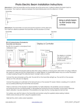
Alternative A. Both the transmitter and the receiver are at the same end. A reflector reflects the beam back to
the receiver. The maximum distance between the transmitter/receiver and the reflector is 18 feet.
Transmitter
Reflector
Receiver
Using a photo beam
to start and/or stop
a timer.
Alternative B. The transmitter is at one end and the receiver is at the other end.
The maximum distance between the transmitter and the receiver is 35 feet.
Transmitter Receiver
IRE-35 Outdoor/Indoor Photoelectric
Transmitter and Receiver Display or Controller
The IRE-35 is housed in a shockproof and
waterproof case.
Transmitter Receiver To Power Connector
Sensitivity
Start/Stop
Ground
Reset
Tallye
Stop
The display or controller
+V
has up to 4 custom
12V
24V
24V
12V
NC
NA
0V
0V
programmable ground
C
closure inputs.
Power Source: 12 to 15VDC or
9 to 13 VAC
Wall
Transformer
Install the transmitter and receiver side by side when using a reflector, or facing each other when not using a reflector.
Be careful to make sure that the infrared beam is closely aligned. Un predictable results may occur when the person
or object passing throught the reflected beam has light colors or is shiny.
Connect the wire and power up the units. The red LED on the transmitter will light up. The red LED on the receiver
will be on if the units are not aligned.
Connect the probes of a voltmeter to the test point pins on the receiver PC board. Obtain a reading of 0.4 volts DC.
by accurately positioning the transmitter and receiver.
There is a trimmer on the receiver to adjust sensitivity. For faster detection, the sensitivity can be increased
by turning the trimmer counterclockwise, or decreased by turning the trimmer clockwise. At short beam distances
beam saturation may slow detection if the sensitivity is too high and the moving objects small and fast.
For outdoor use, seal the holes on the transmitter and receiver using the supplied rubber sealing material.
Install covers and secure them using the supplied screws.
Walk test the units to verify correct operation.
www.alzatex.com www.alzatex.com photo_beam_wiring.pdf