SlideShare ist ein Scribd-Unternehmen logo
1 von 40
Downloaden Sie, um offline zu lesen
AAVVIIOONNIICCSS 
TTEECCHHNNOOLLOOGGYY 
BBaassiicc RRaaddiioo SSyysstteemm 
CCoommppoonneennttss 
Amplifiers 
An amplifier is a device that 
increases the strength of a signal. 
 They are found in both 
transmitters and receivers. 
A transmitter must increase the 
strength of the signal sent to the 
antenna so that the EM waves will 
travel a useful distance outward 
from the antenna. 
A receiver needs amplifiers because 
the strength of the signal from the 
antenna is very low and must be 
increased to enable the signal to be 
heard. 
Amplifiers can be categorized as 
Class A, Class B and Class C. 
 The difference between these is 
the shape of the output 
waveform. 
The output of a Class A amplifier 
is complete sine waves just like the 
input. 
The Class B amplifier has an 
output which shows only half of 
each sine wave. 
The Class C amplifier has an 
output waveform which is less than 
half of the sine wave 
AV2220 - Aircraft Communication Systems Chapter 1 1
AAVVIIOONNIICCSS 
TTEECCHHNNOOLLOOGGYY 
Amplifiers (cont’d) 
The Class C amplifier is often used 
as a power amplifier because of its 
higher efficiency. 
The output of the Class C amplifier 
can be sent through an LC circuit or 
other device to restore the 
complete sine wave shape. 
An example of the output waveform 
for Class A, B and C amplifiers 
AV2220 - Aircraft Communication Systems Chapter 1 2
AAVVIIOONNIICCSS 
TTEECCHHNNOOLLOOGGYY 
Oscillators 
An oscillator is a device that 
produces the frequencies needed by 
both receivers and transmitters. 
A simple oscillator is an LC circuit or 
tank circuit made up of a capacitor 
and inductor in parallel. 
The LC circuit will have a resonant 
frequency which matches the 
desired frequency. 
An LC circuit by itself will not 
continue to oscillate because of 
resistance in the components and 
wires. 
A parallel LC tank circuit. 
AV2220 - Aircraft Communication Systems Chapter 1 3
AAVVIIOONNIICCSS 
TTEECCHHNNOOLLOOGGYY 
Oscillators (cont’d) 
An LC tank circuit which connected 
to a battery can produce 
oscillations. 
If the switch in Figure on the right-side 
is moved to position A, the 
capacitor will be charged by the 
battery. 
If the switch is then moved to 
position C, the tank circuit will start 
to oscillate as energy is transferred 
rapidly back and forth between the 
capacitor and inductor. 
The oscillations will become weaker 
and die out because of the 
resistance in the circuit. 
A parallel LC tank circuit 
AV2220 - Aircraft Communication Systems Chapter 1 4
AAVVIIOONNIICCSS 
TTEECCHHNNOOLLOOGGYY 
Oscillators (cont’d) 
In order to maintain oscillations, 
some energy must be fed back into 
the tank circuit. 
The resonant frequency or 
oscillation frequency is determined 
by the values of capacitance and 
inductance in the tank circuit. 
The LC circuit will not be stable 
over a period of time and may drift 
off the correct frequency. 
An oscillator circuit with feedback 
supplied by a transistor 
AV2220 - Aircraft Communication Systems Chapter 1 5
AAVVIIOONNIICCSS 
TTEECCHHNNOOLLOOGGYY 
Oscillators (cont’d) 
A common technique to stabilize 
the oscillator and produce a more 
accurate frequency is to use a 
crystal. 
The piezoelectric effect of the 
crystal will produce a more accurate 
and consistent output frequency 
from the oscillator. 
A crystal controlled oscillator 
AV2220 - Aircraft Communication Systems Chapter 1 6
AAVVIIOONNIICCSS 
TTEECCHHNNOOLLOOGGYY 
Modulators and Demodulators 
In the radio transmitter, a device is 
needed which will combine the AF 
signal with the RF carrier wave 
signal before it is sent to the 
antenna. 
This is the function of a modulator, 
it combines the AF and RF signals 
so that information can be 
transmitted. 
The output of the modulator is 
called modulated RF. 
The signal produced by the antenna 
in a receiver will be modulated RF. 
In order to hear the voice as an 
output of the receiver, the AF 
component must be separated out. 
The demodulator removes the RF 
component of the modulated RF 
signal and produces an AF output. 
When the AF and RF signals are 
combined in the modulator, they 
must have the proper relative 
strengths for maximum efficiency. 
The amount of modulation is called 
the modulation rate. 
AV2220 - Aircraft Communication Systems Chapter 1 7
AAVVIIOONNIICCSS 
TTEECCHHNNOOLLOOGGYY 
Modulators and Demodulators 
If the AF signal is too weak 
compared to the RF signal, the 
modulation rate will be low and the 
efficiency will also be low. 
If the modulation rate is over 
100%, there will be distortion in the 
signal due to the gaps created. 
Figure (on the right-side) gives 
examples of 50%, 100% and more 
than 100% modulation rates with 
AM modulation. 
Most radio transmitters are adjusted 
to about 90‑95% modulation to 
provide a little margin to prevent 
distortion. 
Examples of different modulation rates 
(A) 50%; (B) 100%;(C) Over 100% 
AV2220 - Aircraft Communication Systems Chapter 1 8
AAVVIIOONNIICCSS 
TTEECCHHNNOOLLOOGGYY 
Filters 
A filter is used in a radio circuit to 
remove or filter out unwanted 
frequencies. 
The signals that are processed by 
the circuits in a radio often have 
additional frequencies present that 
are not needed. 
If the proper filter is installed, it will 
filter out the frequency or 
frequencies that are not wanted. 
A filter is usually made up of an 
arrangement of inductors and 
capacitors. 
Radio frequency filters are combinations of 
inductors and capacitors 
AV2220 - Aircraft Communication Systems Chapter 1 9
AAVVIIOONNIICCSS 
TTEECCHHNNOOLLOOGGYY 
Filters (cont’d) 
A low pass filter will remove all 
frequencies above a certain value 
and pass the low ones. 
A high pass filter does the 
opposite. If a range of frequencies 
must be blocked, a band reject filter 
will be used. 
A bandpass filter will allow a 
certain band of frequencies to go 
through and block frequencies 
either above or below that range. 
Radio frequency filters are combinations of 
inductors and capacitors 
AV2220 - Aircraft Communication Systems Chapter 1 10
AAVVIIOONNIICCSS 
TTEECCHHNNOOLLOOGGYY 
Antennas 
An antenna is a device that 
transforms electrical signals into EM 
waves in the case of a transmit 
antenna, or transforms EM waves 
into electrical signals in the case of 
a receive antenna. 
An antenna may be used for 
transmit only, receive only, or both, 
depending on the particular radio 
system involved. 
The maintenance, inspection and 
installation of antennas are usually 
the responsibility of the airframe 
technician since they are attached 
to the structure or skin of the 
aircraft. 
Three characteristics of an antenna 
are critical: 
 length, 
 polarization 
 directivity. 
For an antenna to be most efficient, 
its length must be one-half the 
wavelength of the signal being 
transmitted or received. 
 This length allows the antenna 
current to be maximum. 
AV2220 - Aircraft Communication Systems Chapter 1 11
AAVVIIOONNIICCSS 
TTEECCHHNNOOLLOOGGYY 
Antennas (cont’d) 
To induce the maximum amount of 
voltage into the receiving antenna, 
the antenna must be installed in 
such away that it is: 
 perpendicular to the magnetic, 
H, field in the radio waves. 
 parallel to the electric, E, field 
in the radio waves. 
When the transmitting antenna is 
vertical, the E field is vertical, and 
the radiation is said to be 
vertically polarized. 
 The maximum reception is picked 
up with a vertical antenna. 
When the transmitting antenna is 
horizontal, the radiation is 
horizontally polarized, and is 
best received on a horizontal 
antenna. 
When the transmitting antenna is 
vertical, its electric field is vertical 
and the magnetic field is horizontal. 
 It is picked up best by a vertical 
antenna. 
Most LF, MF, and HF 
communication use horizontally 
polarized antennas, and 
Higher frequency systems use 
vertically polarized antennas. 
AV2220 - Aircraft Communication Systems Chapter 1 12
AAVVIIOONNIICCSS 
TTEECCHHNNOOLLOOGGYY 
Antennas (cont’d) 
The dipole antenna in A transmits 
its signal strongest in a direction 
perpendicular to its length. 
The vertical whip antenna in B has 
a uniform field strength in all 
directions and is called an 
onmidirectional antenna. 
The loop antenna in C is highly 
directional. 
 Its strength is sharply reduced in 
the direction perpendicular to its 
plane. 
Directional characteristics of typical antennas 
AV2220 - Aircraft Communication Systems Chapter 1 13
AAVVIIOONNIICCSS 
TTEECCHHNNOOLLOOGGYY 
Antennas (cont’d) 
Antennas often have general names 
that describe some of their basic 
characteristics. 
Two of the more common types are 
the Hertz dipole antenna and the 
Marconi monopole antenna. 
The Hertz dipole antenna has two 
metal conductors in a straight line 
with the connection in the middle. 
 It is called a half‑wave 
antenna because the overall 
length is equal to one half the 
wavelength of the EM wave it is 
designed to be used with. 
The Hertz dipole antenna is a half‑wave antenna 
AV2220 - Aircraft Communication Systems Chapter 1 14
AAVVIIOONNIICCSS 
TTEECCHHNNOOLLOOGGYY 
Antennas (cont’d) 
The Marconi antenna is a single 
metal conductor with a length of ¼ 
wavelength. 
In order to work properly, the 
Marconi antenna must have metal 
surrounding the mounting base. 
 The metal at the base is needed 
for efficient operation of the 
antenna. 
 The necessary metal at the base 
is called the groundplane or 
counterpoise. 
The Marconi antenna is a ¼ ‑wave monopole antenna 
that requires a groundplane 
AV2220 - Aircraft Communication Systems Chapter 1 15
AAVVIIOONNIICCSS 
TTEECCHHNNOOLLOOGGYY 
Antennas (cont’d) 
The groundplane is the four metal 
rods at the base of the antenna; 
 the metal skin of an aircraft is 
used as a groundplane for most 
aircraft antennas. 
Most antennas must be installed 
with the correct polarization. 
Polarization refers to the orientation 
of the electric field relative to the 
earth. 
 If the electric field is vertical, it 
has vertical polarization. 
The Marconi antenna is a ¼ ‑wave monopole antenna 
that requires a groundplane 
AV2220 - Aircraft Communication Systems Chapter 1 16
AAVVIIOONNIICCSS 
TTEECCHHNNOOLLOOGGYY 
Antennas (cont’d) 
A horizontally polarized Hertz antenna will produce 
this type of radiation pattern 
A vertically polarized Marconi antenna will produce 
this type of radiation pattern 
AV2220 - Aircraft Communication Systems Chapter 1 17
AAVVIIOONNIICCSS 
TTEECCHHNNOOLLOOGGYY 
Antennas (cont’d) 
The connection between an 
antenna and a radio normally 
requires a coupler in order to give 
the best transfer of energy between 
the two of them. 
Two common types of antenna 
couplers are the LC circuit and the 
transformer types. 
An isolation transformer can be 
used as an antenna coupling 
device. 
A transformer type of coupler antenna 
AV2220 - Aircraft Communication Systems Chapter 1 18
AAVVIIOONNIICCSS 
TTEECCHHNNOOLLOOGGYY 
Antennas (cont’d) 
The use of an LC circuit as a 
coupler between the coax and 
antenna is shown in Figure below. 
In the past, long-wire trailing 
antennas were used for HF 
communication. 
But advances in communication 
technology have developed tuned 
antennas that are actually part of 
the aircraft structure. 
Other aircraft use a copper-clad 
steel wire enclosed in a 
polyethylene covering run from 
outside the fuselage above the 
cockpit to the top of the vertical fin. 
An LC circuit used as an antenna coupler 
AV2220 - Aircraft Communication Systems Chapter 1 19
AAVVIIOONNIICCSS 
TTEECCHHNNOOLLOOGGYY 
Antennas (cont’d) 
VHF communication uses the 
frequencies between 118 and 136 
megahertz, which are just above 
the VOR frequencies, and the 
antenna used is normally a 
quarter-wavelength, vertically 
polarized whip. 
The metal in the aircraft structure 
provides the other quarter-wavelength 
to make the antenna 
electrically a half-wavelength long. 
Many whip antennas are bent so 
they can also pick up horizontally 
polarized signals. 
Broad-band blade antennas provide 
more efficient transmission and 
reception than simple whips. 
AV2220 - Aircraft Communication Systems Chapter 1 20
AAVVIIOONNIICCSS 
TTEECCHHNNOOLLOOGGYY 
Tuning Circuits 
An antenna will intercept many 
different EM waves of different 
frequencies so some method must 
be used to separate out the desired 
frequency. 
 The tuning circuit performs this 
function. 
As the tuning knob is rotated on the 
radio, it moves the variable 
capacitor until the resonant 
frequency of the circuit matches the 
frequency of the desired station. 
 This signal is passed into the 
radio and the other frequencies 
are blocked out. 
A simple tuning circuit which consists of 
a variable capacitor and an inductor in parallel 
AV2220 - Aircraft Communication Systems Chapter 1 21
AAVVIIOONNIICCSS 
TTEECCHHNNOOLLOOGGYY 
Tuning Circuits (cont’d) 
A better type of tuner which is 
found on most modern radios uses 
a frequency synthesizer which 
contains a number of crystals that 
can be combined to match the 
desired frequency. 
Each crystal has a particular 
frequency and by using switches 
the crystals can be combined to 
produce many additional 
frequencies. 
When two frequencies are 
combined, two new frequencies are 
created that are equal to the sum 
and the difference of the two 
frequencies. 
The basic operation of a frequency synthesizer 
AV2220 - Aircraft Communication Systems Chapter 1 22
AAVVIIOONNIICCSS 
TTEECCHHNNOOLLOOGGYY 
Transmitters 
Simplified block diagram of a voice radio transmitter 
AV2220 - Aircraft Communication Systems Chapter 1 23
AAVVIIOONNIICCSS 
TTEECCHHNNOOLLOOGGYY 
Transmitters (cont’d) 
A simple voice radio transmitter consists of: 
 Frequency oscillator which operates at one half the carrier frequency 
 Buffer amplifier and frequency doubler which assigned to amplify and doubling 
the signal so that it has enough power to radiate into space when it goes to the 
antenna. 
 The modulator combines the AF and RF signals 
 The power amp which operates to amplify signal before being sent down the 
coax to the antenna. 
The transmitter uses a crystal oscillator to produce an accurately controlled 
carrier frequency, and only this one frequency radiates from the transmitter 
antenna. 
In order for a receiver to be useful, it must filter out every frequency except the 
one that is wanted. 
 To do this, it employs a special superheterodyne circuit. 
AV2220 - Aircraft Communication Systems Chapter 1 24
AAVVIIOONNIICCSS 
TTEECCHHNNOOLLOOGGYY 
Receivers 
In the 1920s, a new type of radio receiver was invented that produced 
better sound quality. 
 It was called the superheterodyne or superhet radio. 
The only major difference between the superhet and earlier radios was 
that it reduced the modulated RF signal from the antenna to an AF 
signal in more than one jump or stage. 
AV2220 - Aircraft Communication Systems Chapter 1 25
AAVVIIOONNIICCSS 
TTEECCHHNNOOLLOOGGYY 
Receivers 
Simplified block diagram of a superheterodyne VHF voice radio receiver 
AV2220 - Aircraft Communication Systems Chapter 1 26
AAVVIIOONNIICCSS 
TTEECCHHNNOOLLOOGGYY 
Receivers (cont’d) 
In a VHF superhet aircraft receiver block diagram above: 
 The RF signal from the antenna is combined with a local oscillator frequency to 
produce a lower IF frequency. 
 The intermediate frequencies found in a superhet radio are abbreviated as IF. 
 The output of the mixer is the difference between the RF frequency and the 
local oscillator frequency. 
The basic principle of the mixer is: 
 two different frequencies are combined, 
 two new frequencies are created; the sum and the difference of the two 
combined frequencies. 
 The IF signals is amplified and then sent to the detector and demodulator. 
 The detector chops off half of each sine wave to produce a varying DC signal 
from an AC signal. 
 The AF signal is amplified and used to drive the speaker. 
AV2220 - Aircraft Communication Systems Chapter 1 27
AAVVIIOONNIICCSS 
TTEECCHHNNOOLLOOGGYY 
Receivers (cont’d) 
A tunable local oscillator is included 
in this circuit. 
 The frequency of this oscillator is 
varied so it is always a specific 
frequency higher than the 
frequency to which the 
preamplifier is tuned. 
For most broadcast band receivers, 
the frequency of the local oscillator 
is always 455 kilohertz higher than 
the frequency tuned on the 
preamplifier. 
 In this case, the local oscillator 
produces a signal with a 
frequency of 1,655 kilohertz 
(1,200 + 455). 
The antenna picks up all the radio 
signals in the area and they are 
taken into a tunable preamplifier. 
 This preamplifier uses an 
electronic filter circuit that passes 
only the frequency to which the 
receiver is tuned and sends all of 
the other frequencies to ground. 
The preamplifier amplifies any 
signal with a frequency of e.g. 
1,200 kHz and passes all other 
frequencies to ground. 
AV2220 - Aircraft Communication Systems Chapter 1 28
AAVVIIOONNIICCSS 
TTEECCHHNNOOLLOOGGYY 
Receivers (cont’d) 
The four signals will have 
frequencies of: 
 1,200 kHz 
 1,655 kHz 
 2,855 kHz (1,200 + 1,655) 
 455 kHz (1,655 - 1,200) 
The four signals from the mixer are 
sent into the intermediate 
frequency (IF) amplifier. 
This is a very narrow-band amplifier 
that is tuned to 455 kHz. 
It amplifies the 455 kHz signal and 
attenuates, or diminishes, all other 
frequencies. 
The signals from the preamplifier 
and the local oscillator are sent to 
the mixer. 
When signals with two frequencies 
are mixed, they produce two other 
signals: 
 one with a frequency that is the 
sum of the original two 
frequencies and 
 the other with a frequency that is 
the difference between the two. 
AV2220 - Aircraft Communication Systems Chapter 1 29
AAVVIIOONNIICCSS 
TTEECCHHNNOOLLOOGGYY 
Receivers (cont’d) 
The amplified 455 kHz signal is sent to the detector/demodulator 
 It removes the 455 kHz IF carrier and leaves the AF envelope that has both 
halves of the audio signal. 
The detector rectifies the AF signal and removes one half of the envelope. 
The AF signal is amplified by a power amplifier stage and drives the speaker. 
The output of the speaker is the same as the input to the microphone at the 
transmitter. 
AV2220 - Aircraft Communication Systems Chapter 1 30
AAVVIIOONNIICCSS 
TTEECCHHNNOOLLOOGGYY 
Receivers (cont’d) 
Communication receivers such as those used in aircraft are more sensitive than 
the normal household broadcast receiver, and they have more stages. 
A simplified block diagram of a VHF superhet communication receiver 
AV2220 - Aircraft Communication Systems Chapter 1 31
AAVVIIOONNIICCSS 
TTEECCHHNNOOLLOOGGYY 
Receivers (cont’d) 
The signal is picked up on the 
antenna and amplified by the tuned 
preamplifier. 
The local oscillator produces a 
frequency that is 10.8-megahertz 
different from the frequency to 
which the preamplifier is tuned. 
These two frequencies are fed into 
the mixer where they produce a 
10.8-MHz intermediate frequency. 
This IF is amplified by two stages of 
IF amplification and sent into the 
detector/demodulator, where it 
emerges as an audio frequency 
signal that duplicates the AF 
produced by the microphone at the 
transmitter. 
Some of the detector output is sent 
into a squelch circuit that controls 
the audio frequency amplifier. 
When no signal is being received, 
the AF amplifier output is 
attenuated, or decreased, so the 
background noise that makes a 
hissing sound in the speaker is not 
loud enough to be annoying. 
AV2220 - Aircraft Communication Systems Chapter 1 32
AAVVIIOONNIICCSS 
TTEECCHHNNOOLLOOGGYY 
Speakers and Microphones 
Aircraft radios often supply an audio 
output for the pilot and voice 
transmitters require an audio input 
from a microphone. 
A speaker is a device that 
transforms electrical signals into 
sound waves. 
When the audio frequency signal is 
applied to the windings in the 
speaker, it sets up a magnetic field 
that expands and contracts at an 
audio rate. 
A dynamic speaker 
AV2220 - Aircraft Communication Systems Chapter 1 33
AAVVIIOONNIICCSS 
TTEECCHHNNOOLLOOGGYY 
Speakers and Microphones (cont’d) 
The magnetic field causes the metal 
diaphragm to vibrate at a 
corresponding rate to produce the 
movement of air that generates 
sound waves. 
Dynamic microphones are available 
which operate in the opposite way. 
Many newer and more efficient 
types of microphones are now 
being manufactured, but they all 
work by transforming the vibrations 
of sound waves into varying 
electrical signals. 
A dynamic speaker 
AV2220 - Aircraft Communication Systems Chapter 1 34
AAVVIIOONNIICCSS 
TTEECCHHNNOOLLOOGGYY 
Audio Control Panel 
When an aircraft has more than one 
radio, an efficient means of 
switching the microphone and 
speaker connections from one radio 
to another is needed. 
 The audio control panel performs 
this function. 
An audio control panel is not a radio 
because it only uses audio 
frequencies, but it is associated 
with the radios in the aircraft. 
A typical audio control panel 
AV2220 - Aircraft Communication Systems Chapter 1 35
AAVVIIOONNIICCSS 
TTEECCHHNNOOLLOOGGYY 
Audio Control Panel (cont’d) 
This audio control panel has a row 
of toggle switches that can be used 
to connect the audio output of the 
various radios to the speaker or 
headphones. 
It also has a rotary selector switch 
to connect the microphone audio 
output to the different radio 
transmitters and intercom systems 
available for the aircraft. 
The audio control panel illustrated 
also has three lights that are the 
indicators for the marker beacon 
system on the aircraft. 
A typical audio control panel 
AV2220 - Aircraft Communication Systems Chapter 1 36
AAVVIIOONNIICCSS 
TTEECCHHNNOOLLOOGGYY 
RReegguullaattiioonnss aanndd 
SSttaannddaarrddss ffoorr RRaaddiiooss 
Aircraft avionics equipment might 
have to comply with a number of 
different regulations and standards 
depending on the type of 
equipment and the type of aircraft 
in which it is installed. 
Regulations from the FAA and the 
FCC apply to the manufacture and 
use of most types of equipment and 
carry the force of law. 
FAA standards for equipment are 
usually in the form of TSO 
(Technical Standard Order) 
approvals. 
FCC rules generally apply to 
equipment which produces radio 
waves. 
An FCC Station License is required 
for aircraft that have radio 
transmitters other than ELT. 
Each different type of transmitter 
must be listed on the license that is 
displayed in the cockpit. 
The role of ARINC in established 
standards apply to the equipment in 
air carrier jets and bizjets primarily. 
There are some FAA Regulations 
concerning the use of radio 
equipment in flight. 
AV2220 - Aircraft Communication Systems Chapter 1 37
AAVVIIOONNIICCSS 
TTEECCHHNNOOLLOOGGYY 
FAR 91.130 (c) 
No person may operate an aircraft in an Airport Radar Service Area (ARSA) 
unless two‑way radio communication is established and maintained with ATC. 
A transponder with Mode C automatic reporting of aircraft pressure altitude is 
also required in all ARSAs. 
FAR 91.131 (c) and (d) 
No person may operate an aircraft in a Terminal Control Area (TCA) unless it 
has: 
1. A two‑way radio with appropriate frequencies available. 
2. An operable transponder with Mode C altitude reporting. 
AV2220 - Aircraft Communication Systems Chapter 1 38
AAVVIIOONNIICCSS 
TTEECCHHNNOOLLOOGGYY 
FAR 91.205 (d) and (e) Minimum Equipment Requirements for 
IFR 
 Two‑way radio communications and navigation equipment appropriate to the 
ground facilities that will be used. 
 At and above 24,000 ft. MSL; approved DME (distance measuring equipment). 
AV2220 - Aircraft Communication Systems Chapter 1 39
AAVVIIOONNIICCSS 
TTEECCHHNNOOLLOOGGYY 
FAR 91.511 
Large and turbine ‑powered, multi‑engine airplanes, if operating over water 
more than 30 minutes or 100 nautical miles from the nearest shoreline, must 
have: 
1. Radio communication equipment appropriate to the ground facilities. 
2. Two transmitters. 
3. Two microphones. 
4. Two headsets (or headset and speaker). 
5. Two independent receivers. 
6. If needed, one HF transceiver. 
AV2220 - Aircraft Communication Systems Chapter 1 40

Weitere ähnliche Inhalte

Was ist angesagt?

Nav Topic 8 automatic direction finder
Nav Topic 8 automatic direction finderNav Topic 8 automatic direction finder
Nav Topic 8 automatic direction finder
Izah Asmadi
 
Avionics Systems Instruments
Avionics Systems InstrumentsAvionics Systems Instruments
Avionics Systems Instruments
Michael Bseliss
 
Nav Topic 5 selcal and data link system
Nav Topic 5 selcal and data link systemNav Topic 5 selcal and data link system
Nav Topic 5 selcal and data link system
Izah Asmadi
 
Aircraft navigation system
Aircraft navigation systemAircraft navigation system
Aircraft navigation system
Krishikesh Singh
 
Vor navigation and_tracking
Vor navigation and_trackingVor navigation and_tracking
Vor navigation and_tracking
drbagwell
 
Aircraft Auto Pilot Roll Control System
Aircraft Auto Pilot Roll Control SystemAircraft Auto Pilot Roll Control System
Aircraft Auto Pilot Roll Control System
Suchit Moon
 
Air Traffic Control and Nav Aids
Air Traffic Control and Nav AidsAir Traffic Control and Nav Aids
Air Traffic Control and Nav Aids
Emmanuel Fuchs
 

Was ist angesagt? (20)

Nav Topic 8 automatic direction finder
Nav Topic 8 automatic direction finderNav Topic 8 automatic direction finder
Nav Topic 8 automatic direction finder
 
Avionics Systems Instruments
Avionics Systems InstrumentsAvionics Systems Instruments
Avionics Systems Instruments
 
A presentation on internship from jaipur Airport [AAI]
A presentation on internship from jaipur Airport [AAI]A presentation on internship from jaipur Airport [AAI]
A presentation on internship from jaipur Airport [AAI]
 
Nav Topic 5 selcal and data link system
Nav Topic 5 selcal and data link systemNav Topic 5 selcal and data link system
Nav Topic 5 selcal and data link system
 
Avionics
AvionicsAvionics
Avionics
 
Aircraft Communication Topic 4 hf communication system
Aircraft Communication  Topic 4 hf communication systemAircraft Communication  Topic 4 hf communication system
Aircraft Communication Topic 4 hf communication system
 
ACARS
ACARSACARS
ACARS
 
B737 NG Communications
B737 NG CommunicationsB737 NG Communications
B737 NG Communications
 
VHF Communication Basics Part 3
VHF Communication  Basics Part 3VHF Communication  Basics Part 3
VHF Communication Basics Part 3
 
V.o.r ppt
V.o.r pptV.o.r ppt
V.o.r ppt
 
Aircraft Communication Topic 5 selcal and data link system
Aircraft Communication  Topic 5 selcal and data link systemAircraft Communication  Topic 5 selcal and data link system
Aircraft Communication Topic 5 selcal and data link system
 
Aircraft navigation system
Aircraft navigation systemAircraft navigation system
Aircraft navigation system
 
Instrument Landing System
Instrument Landing SystemInstrument Landing System
Instrument Landing System
 
Vor navigation and_tracking
Vor navigation and_trackingVor navigation and_tracking
Vor navigation and_tracking
 
Avionics buses
Avionics busesAvionics buses
Avionics buses
 
DME in Aviation||| Avionics || Distance Measuring Equipment
DME in Aviation||| Avionics || Distance Measuring EquipmentDME in Aviation||| Avionics || Distance Measuring Equipment
DME in Aviation||| Avionics || Distance Measuring Equipment
 
RADIO NAVIGATION.pptx
RADIO NAVIGATION.pptxRADIO NAVIGATION.pptx
RADIO NAVIGATION.pptx
 
PPt on AAI
PPt on AAIPPt on AAI
PPt on AAI
 
Aircraft Auto Pilot Roll Control System
Aircraft Auto Pilot Roll Control SystemAircraft Auto Pilot Roll Control System
Aircraft Auto Pilot Roll Control System
 
Air Traffic Control and Nav Aids
Air Traffic Control and Nav AidsAir Traffic Control and Nav Aids
Air Traffic Control and Nav Aids
 

Ähnlich wie Aircraft Communication Topic 3 radio components

Nav Topic 3 radio components
Nav Topic 3 radio componentsNav Topic 3 radio components
Nav Topic 3 radio components
Izah Asmadi
 
Chapter 47
Chapter 47Chapter 47
Chapter 47
mcfalltj
 
Aircraft Communication Topic 2 modulation and propagation of radio waves
Aircraft Communication  Topic 2 modulation and propagation of radio wavesAircraft Communication  Topic 2 modulation and propagation of radio waves
Aircraft Communication Topic 2 modulation and propagation of radio waves
Izah Asmadi
 
Nav Topic 2 modulation and propagation of radio waves
Nav Topic 2 modulation and propagation of radio wavesNav Topic 2 modulation and propagation of radio waves
Nav Topic 2 modulation and propagation of radio waves
Izah Asmadi
 
Halderman ch061 lecture
Halderman ch061 lectureHalderman ch061 lecture
Halderman ch061 lecture
mcfalltj
 
Paper id 36201528
Paper id 36201528Paper id 36201528
Paper id 36201528
IJRAT
 
Nav Topic 1 basic radio wave properties
Nav Topic 1 basic radio wave propertiesNav Topic 1 basic radio wave properties
Nav Topic 1 basic radio wave properties
Izah Asmadi
 
Modulation types-amplitude,frequency,phase modulation,
Modulation types-amplitude,frequency,phase modulation,Modulation types-amplitude,frequency,phase modulation,
Modulation types-amplitude,frequency,phase modulation,
gayatri suthar
 

Ähnlich wie Aircraft Communication Topic 3 radio components (20)

Nav Topic 3 radio components
Nav Topic 3 radio componentsNav Topic 3 radio components
Nav Topic 3 radio components
 
Chapter 47
Chapter 47Chapter 47
Chapter 47
 
Aircraft Communication Topic 2 modulation and propagation of radio waves
Aircraft Communication  Topic 2 modulation and propagation of radio wavesAircraft Communication  Topic 2 modulation and propagation of radio waves
Aircraft Communication Topic 2 modulation and propagation of radio waves
 
AM RECEIVERS 2.docx
AM RECEIVERS 2.docxAM RECEIVERS 2.docx
AM RECEIVERS 2.docx
 
0 lecture 3 wp wireless protocol
0 lecture 3 wp wireless protocol0 lecture 3 wp wireless protocol
0 lecture 3 wp wireless protocol
 
Nav Topic 2 modulation and propagation of radio waves
Nav Topic 2 modulation and propagation of radio wavesNav Topic 2 modulation and propagation of radio waves
Nav Topic 2 modulation and propagation of radio waves
 
Topic 1 basic radio wave properties
Topic 1 basic radio wave propertiesTopic 1 basic radio wave properties
Topic 1 basic radio wave properties
 
Transistor Amplifire.pptx
Transistor Amplifire.pptxTransistor Amplifire.pptx
Transistor Amplifire.pptx
 
Antenna Tuning Units for better reception.pdf
Antenna Tuning Units for better reception.pdfAntenna Tuning Units for better reception.pdf
Antenna Tuning Units for better reception.pdf
 
Electronics and Communication Engineering
Electronics and Communication EngineeringElectronics and Communication Engineering
Electronics and Communication Engineering
 
Halderman ch061 lecture
Halderman ch061 lectureHalderman ch061 lecture
Halderman ch061 lecture
 
Paper id 36201528
Paper id 36201528Paper id 36201528
Paper id 36201528
 
Types of klystron Amplifier
Types of klystron AmplifierTypes of klystron Amplifier
Types of klystron Amplifier
 
Am transmitter
Am transmitterAm transmitter
Am transmitter
 
UNIT III - SIGNAL CONDITIONING CIRCUITS.pptx
UNIT III - SIGNAL CONDITIONING CIRCUITS.pptxUNIT III - SIGNAL CONDITIONING CIRCUITS.pptx
UNIT III - SIGNAL CONDITIONING CIRCUITS.pptx
 
Nav Topic 1 basic radio wave properties
Nav Topic 1 basic radio wave propertiesNav Topic 1 basic radio wave properties
Nav Topic 1 basic radio wave properties
 
Oscillator
OscillatorOscillator
Oscillator
 
Modulation types-amplitude,frequency,phase modulation,
Modulation types-amplitude,frequency,phase modulation,Modulation types-amplitude,frequency,phase modulation,
Modulation types-amplitude,frequency,phase modulation,
 
Electrical Engineering
Electrical EngineeringElectrical Engineering
Electrical Engineering
 
Oscillator
OscillatorOscillator
Oscillator
 

Mehr von Izah Asmadi

Business ethics C7 -business_ethics_environmental_issues
Business ethics C7  -business_ethics_environmental_issuesBusiness ethics C7  -business_ethics_environmental_issues
Business ethics C7 -business_ethics_environmental_issues
Izah Asmadi
 
Business ethics C5 -organizational_ethics_compatibility_mode_
Business ethics C5  -organizational_ethics_compatibility_mode_Business ethics C5  -organizational_ethics_compatibility_mode_
Business ethics C5 -organizational_ethics_compatibility_mode_
Izah Asmadi
 
Business ethics C4 -corporate_social_responsibility_compatibility_mode_
Business ethics C4  -corporate_social_responsibility_compatibility_mode_Business ethics C4  -corporate_social_responsibility_compatibility_mode_
Business ethics C4 -corporate_social_responsibility_compatibility_mode_
Izah Asmadi
 
Business ethics C3 theories principles in_business_ethics
Business ethics C3 theories principles in_business_ethicsBusiness ethics C3 theories principles in_business_ethics
Business ethics C3 theories principles in_business_ethics
Izah Asmadi
 
Business ethics C1 -moral_ethics_ethical_dilemma
Business ethics C1  -moral_ethics_ethical_dilemmaBusiness ethics C1  -moral_ethics_ethical_dilemma
Business ethics C1 -moral_ethics_ethical_dilemma
Izah Asmadi
 
Project Management Ch11 Project Scheduling Critical Chain
Project Management Ch11 Project Scheduling Critical ChainProject Management Ch11 Project Scheduling Critical Chain
Project Management Ch11 Project Scheduling Critical Chain
Izah Asmadi
 
Project Management Ch10
Project Management Ch10 Project Management Ch10
Project Management Ch10
Izah Asmadi
 
Project Management CH9 Project Scheduling
Project Management CH9 Project SchedulingProject Management CH9 Project Scheduling
Project Management CH9 Project Scheduling
Izah Asmadi
 
Project Management C5 -scope_management
Project Management C5  -scope_managementProject Management C5  -scope_management
Project Management C5 -scope_management
Izah Asmadi
 
Project Management C8 -cost_estimation_and_budgeting
Project Management C8  -cost_estimation_and_budgetingProject Management C8  -cost_estimation_and_budgeting
Project Management C8 -cost_estimation_and_budgeting
Izah Asmadi
 
Project Management C6 -project_team_building_conflict_and_negotiation
Project Management C6  -project_team_building_conflict_and_negotiationProject Management C6  -project_team_building_conflict_and_negotiation
Project Management C6 -project_team_building_conflict_and_negotiation
Izah Asmadi
 
Project Management C4 -leadership_and_the_project_manager
Project Management C4  -leadership_and_the_project_managerProject Management C4  -leadership_and_the_project_manager
Project Management C4 -leadership_and_the_project_manager
Izah Asmadi
 
Project Management C3 -project_selection_and_portfolio_management
Project Management C3  -project_selection_and_portfolio_managementProject Management C3  -project_selection_and_portfolio_management
Project Management C3 -project_selection_and_portfolio_management
Izah Asmadi
 

Mehr von Izah Asmadi (20)

Aircraft Communication Topic 10 instrument landing systems
Aircraft Communication Topic 10 instrument landing systemsAircraft Communication Topic 10 instrument landing systems
Aircraft Communication Topic 10 instrument landing systems
 
Aircraft Communication Topic 9 vhf omni range (vor)
Aircraft Communication  Topic 9 vhf omni range (vor)Aircraft Communication  Topic 9 vhf omni range (vor)
Aircraft Communication Topic 9 vhf omni range (vor)
 
Aircraft Communication Topic 8 automatic direction finder
Aircraft Communication  Topic 8 automatic direction finderAircraft Communication  Topic 8 automatic direction finder
Aircraft Communication Topic 8 automatic direction finder
 
Aircraft Communication Topic 7 elt, cvr and fdr
Aircraft Communication  Topic 7 elt, cvr and fdrAircraft Communication  Topic 7 elt, cvr and fdr
Aircraft Communication Topic 7 elt, cvr and fdr
 
Business ethics C8 -ethics_technology
Business ethics C8  -ethics_technologyBusiness ethics C8  -ethics_technology
Business ethics C8 -ethics_technology
 
Business ethics C7 -business_ethics_environmental_issues
Business ethics C7  -business_ethics_environmental_issuesBusiness ethics C7  -business_ethics_environmental_issues
Business ethics C7 -business_ethics_environmental_issues
 
C6 -ethics_and_government_compatibility_mode_
C6  -ethics_and_government_compatibility_mode_C6  -ethics_and_government_compatibility_mode_
C6 -ethics_and_government_compatibility_mode_
 
Business ethics C5 -organizational_ethics_compatibility_mode_
Business ethics C5  -organizational_ethics_compatibility_mode_Business ethics C5  -organizational_ethics_compatibility_mode_
Business ethics C5 -organizational_ethics_compatibility_mode_
 
Business ethics C4 -corporate_social_responsibility_compatibility_mode_
Business ethics C4  -corporate_social_responsibility_compatibility_mode_Business ethics C4  -corporate_social_responsibility_compatibility_mode_
Business ethics C4 -corporate_social_responsibility_compatibility_mode_
 
Business ethics C3 theories principles in_business_ethics
Business ethics C3 theories principles in_business_ethicsBusiness ethics C3 theories principles in_business_ethics
Business ethics C3 theories principles in_business_ethics
 
Business ethics C1 -moral_ethics_ethical_dilemma
Business ethics C1  -moral_ethics_ethical_dilemmaBusiness ethics C1  -moral_ethics_ethical_dilemma
Business ethics C1 -moral_ethics_ethical_dilemma
 
Business ethics C2 -business_and_society
Business ethics C2  -business_and_societyBusiness ethics C2  -business_and_society
Business ethics C2 -business_and_society
 
Project Management Ch11 Project Scheduling Critical Chain
Project Management Ch11 Project Scheduling Critical ChainProject Management Ch11 Project Scheduling Critical Chain
Project Management Ch11 Project Scheduling Critical Chain
 
Project Management Ch10
Project Management Ch10 Project Management Ch10
Project Management Ch10
 
Project Management CH9 Project Scheduling
Project Management CH9 Project SchedulingProject Management CH9 Project Scheduling
Project Management CH9 Project Scheduling
 
Project Management C5 -scope_management
Project Management C5  -scope_managementProject Management C5  -scope_management
Project Management C5 -scope_management
 
Project Management C8 -cost_estimation_and_budgeting
Project Management C8  -cost_estimation_and_budgetingProject Management C8  -cost_estimation_and_budgeting
Project Management C8 -cost_estimation_and_budgeting
 
Project Management C6 -project_team_building_conflict_and_negotiation
Project Management C6  -project_team_building_conflict_and_negotiationProject Management C6  -project_team_building_conflict_and_negotiation
Project Management C6 -project_team_building_conflict_and_negotiation
 
Project Management C4 -leadership_and_the_project_manager
Project Management C4  -leadership_and_the_project_managerProject Management C4  -leadership_and_the_project_manager
Project Management C4 -leadership_and_the_project_manager
 
Project Management C3 -project_selection_and_portfolio_management
Project Management C3  -project_selection_and_portfolio_managementProject Management C3  -project_selection_and_portfolio_management
Project Management C3 -project_selection_and_portfolio_management
 

Kürzlich hochgeladen

Cara Menggugurkan Sperma Yang Masuk Rahim Biyar Tidak Hamil
Cara Menggugurkan Sperma Yang Masuk Rahim Biyar Tidak HamilCara Menggugurkan Sperma Yang Masuk Rahim Biyar Tidak Hamil
Cara Menggugurkan Sperma Yang Masuk Rahim Biyar Tidak Hamil
Cara Menggugurkan Kandungan 087776558899
 
Verification of thevenin's theorem for BEEE Lab (1).pptx
Verification of thevenin's theorem for BEEE Lab (1).pptxVerification of thevenin's theorem for BEEE Lab (1).pptx
Verification of thevenin's theorem for BEEE Lab (1).pptx
chumtiyababu
 
Kuwait City MTP kit ((+919101817206)) Buy Abortion Pills Kuwait
Kuwait City MTP kit ((+919101817206)) Buy Abortion Pills KuwaitKuwait City MTP kit ((+919101817206)) Buy Abortion Pills Kuwait
Kuwait City MTP kit ((+919101817206)) Buy Abortion Pills Kuwait
jaanualu31
 
DeepFakes presentation : brief idea of DeepFakes
DeepFakes presentation : brief idea of DeepFakesDeepFakes presentation : brief idea of DeepFakes
DeepFakes presentation : brief idea of DeepFakes
MayuraD1
 
Call Girls in South Ex (delhi) call me [🔝9953056974🔝] escort service 24X7
Call Girls in South Ex (delhi) call me [🔝9953056974🔝] escort service 24X7Call Girls in South Ex (delhi) call me [🔝9953056974🔝] escort service 24X7
Call Girls in South Ex (delhi) call me [🔝9953056974🔝] escort service 24X7
9953056974 Low Rate Call Girls In Saket, Delhi NCR
 

Kürzlich hochgeladen (20)

AIRCANVAS[1].pdf mini project for btech students
AIRCANVAS[1].pdf mini project for btech studentsAIRCANVAS[1].pdf mini project for btech students
AIRCANVAS[1].pdf mini project for btech students
 
Cara Menggugurkan Sperma Yang Masuk Rahim Biyar Tidak Hamil
Cara Menggugurkan Sperma Yang Masuk Rahim Biyar Tidak HamilCara Menggugurkan Sperma Yang Masuk Rahim Biyar Tidak Hamil
Cara Menggugurkan Sperma Yang Masuk Rahim Biyar Tidak Hamil
 
Computer Networks Basics of Network Devices
Computer Networks  Basics of Network DevicesComputer Networks  Basics of Network Devices
Computer Networks Basics of Network Devices
 
Verification of thevenin's theorem for BEEE Lab (1).pptx
Verification of thevenin's theorem for BEEE Lab (1).pptxVerification of thevenin's theorem for BEEE Lab (1).pptx
Verification of thevenin's theorem for BEEE Lab (1).pptx
 
Thermal Engineering-R & A / C - unit - V
Thermal Engineering-R & A / C - unit - VThermal Engineering-R & A / C - unit - V
Thermal Engineering-R & A / C - unit - V
 
Thermal Engineering Unit - I & II . ppt
Thermal Engineering  Unit - I & II . pptThermal Engineering  Unit - I & II . ppt
Thermal Engineering Unit - I & II . ppt
 
Kuwait City MTP kit ((+919101817206)) Buy Abortion Pills Kuwait
Kuwait City MTP kit ((+919101817206)) Buy Abortion Pills KuwaitKuwait City MTP kit ((+919101817206)) Buy Abortion Pills Kuwait
Kuwait City MTP kit ((+919101817206)) Buy Abortion Pills Kuwait
 
Online food ordering system project report.pdf
Online food ordering system project report.pdfOnline food ordering system project report.pdf
Online food ordering system project report.pdf
 
Tamil Call Girls Bhayandar WhatsApp +91-9930687706, Best Service
Tamil Call Girls Bhayandar WhatsApp +91-9930687706, Best ServiceTamil Call Girls Bhayandar WhatsApp +91-9930687706, Best Service
Tamil Call Girls Bhayandar WhatsApp +91-9930687706, Best Service
 
S1S2 B.Arch MGU - HOA1&2 Module 3 -Temple Architecture of Kerala.pptx
S1S2 B.Arch MGU - HOA1&2 Module 3 -Temple Architecture of Kerala.pptxS1S2 B.Arch MGU - HOA1&2 Module 3 -Temple Architecture of Kerala.pptx
S1S2 B.Arch MGU - HOA1&2 Module 3 -Temple Architecture of Kerala.pptx
 
A CASE STUDY ON CERAMIC INDUSTRY OF BANGLADESH.pptx
A CASE STUDY ON CERAMIC INDUSTRY OF BANGLADESH.pptxA CASE STUDY ON CERAMIC INDUSTRY OF BANGLADESH.pptx
A CASE STUDY ON CERAMIC INDUSTRY OF BANGLADESH.pptx
 
DeepFakes presentation : brief idea of DeepFakes
DeepFakes presentation : brief idea of DeepFakesDeepFakes presentation : brief idea of DeepFakes
DeepFakes presentation : brief idea of DeepFakes
 
COST-EFFETIVE and Energy Efficient BUILDINGS ptx
COST-EFFETIVE  and Energy Efficient BUILDINGS ptxCOST-EFFETIVE  and Energy Efficient BUILDINGS ptx
COST-EFFETIVE and Energy Efficient BUILDINGS ptx
 
Generative AI or GenAI technology based PPT
Generative AI or GenAI technology based PPTGenerative AI or GenAI technology based PPT
Generative AI or GenAI technology based PPT
 
Introduction to Serverless with AWS Lambda
Introduction to Serverless with AWS LambdaIntroduction to Serverless with AWS Lambda
Introduction to Serverless with AWS Lambda
 
Bhubaneswar🌹Call Girls Bhubaneswar ❤Komal 9777949614 💟 Full Trusted CALL GIRL...
Bhubaneswar🌹Call Girls Bhubaneswar ❤Komal 9777949614 💟 Full Trusted CALL GIRL...Bhubaneswar🌹Call Girls Bhubaneswar ❤Komal 9777949614 💟 Full Trusted CALL GIRL...
Bhubaneswar🌹Call Girls Bhubaneswar ❤Komal 9777949614 💟 Full Trusted CALL GIRL...
 
Moment Distribution Method For Btech Civil
Moment Distribution Method For Btech CivilMoment Distribution Method For Btech Civil
Moment Distribution Method For Btech Civil
 
Call Girls in South Ex (delhi) call me [🔝9953056974🔝] escort service 24X7
Call Girls in South Ex (delhi) call me [🔝9953056974🔝] escort service 24X7Call Girls in South Ex (delhi) call me [🔝9953056974🔝] escort service 24X7
Call Girls in South Ex (delhi) call me [🔝9953056974🔝] escort service 24X7
 
Engineering Drawing focus on projection of planes
Engineering Drawing focus on projection of planesEngineering Drawing focus on projection of planes
Engineering Drawing focus on projection of planes
 
NO1 Top No1 Amil Baba In Azad Kashmir, Kashmir Black Magic Specialist Expert ...
NO1 Top No1 Amil Baba In Azad Kashmir, Kashmir Black Magic Specialist Expert ...NO1 Top No1 Amil Baba In Azad Kashmir, Kashmir Black Magic Specialist Expert ...
NO1 Top No1 Amil Baba In Azad Kashmir, Kashmir Black Magic Specialist Expert ...
 

Aircraft Communication Topic 3 radio components

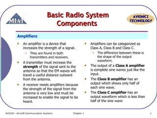
  • 1. AAVVIIOONNIICCSS TTEECCHHNNOOLLOOGGYY BBaassiicc RRaaddiioo SSyysstteemm CCoommppoonneennttss Amplifiers An amplifier is a device that increases the strength of a signal.  They are found in both transmitters and receivers. A transmitter must increase the strength of the signal sent to the antenna so that the EM waves will travel a useful distance outward from the antenna. A receiver needs amplifiers because the strength of the signal from the antenna is very low and must be increased to enable the signal to be heard. Amplifiers can be categorized as Class A, Class B and Class C.  The difference between these is the shape of the output waveform. The output of a Class A amplifier is complete sine waves just like the input. The Class B amplifier has an output which shows only half of each sine wave. The Class C amplifier has an output waveform which is less than half of the sine wave AV2220 - Aircraft Communication Systems Chapter 1 1
  • 2. AAVVIIOONNIICCSS TTEECCHHNNOOLLOOGGYY Amplifiers (cont’d) The Class C amplifier is often used as a power amplifier because of its higher efficiency. The output of the Class C amplifier can be sent through an LC circuit or other device to restore the complete sine wave shape. An example of the output waveform for Class A, B and C amplifiers AV2220 - Aircraft Communication Systems Chapter 1 2
  • 3. AAVVIIOONNIICCSS TTEECCHHNNOOLLOOGGYY Oscillators An oscillator is a device that produces the frequencies needed by both receivers and transmitters. A simple oscillator is an LC circuit or tank circuit made up of a capacitor and inductor in parallel. The LC circuit will have a resonant frequency which matches the desired frequency. An LC circuit by itself will not continue to oscillate because of resistance in the components and wires. A parallel LC tank circuit. AV2220 - Aircraft Communication Systems Chapter 1 3
  • 4. AAVVIIOONNIICCSS TTEECCHHNNOOLLOOGGYY Oscillators (cont’d) An LC tank circuit which connected to a battery can produce oscillations. If the switch in Figure on the right-side is moved to position A, the capacitor will be charged by the battery. If the switch is then moved to position C, the tank circuit will start to oscillate as energy is transferred rapidly back and forth between the capacitor and inductor. The oscillations will become weaker and die out because of the resistance in the circuit. A parallel LC tank circuit AV2220 - Aircraft Communication Systems Chapter 1 4
  • 5. AAVVIIOONNIICCSS TTEECCHHNNOOLLOOGGYY Oscillators (cont’d) In order to maintain oscillations, some energy must be fed back into the tank circuit. The resonant frequency or oscillation frequency is determined by the values of capacitance and inductance in the tank circuit. The LC circuit will not be stable over a period of time and may drift off the correct frequency. An oscillator circuit with feedback supplied by a transistor AV2220 - Aircraft Communication Systems Chapter 1 5
  • 6. AAVVIIOONNIICCSS TTEECCHHNNOOLLOOGGYY Oscillators (cont’d) A common technique to stabilize the oscillator and produce a more accurate frequency is to use a crystal. The piezoelectric effect of the crystal will produce a more accurate and consistent output frequency from the oscillator. A crystal controlled oscillator AV2220 - Aircraft Communication Systems Chapter 1 6
  • 7. AAVVIIOONNIICCSS TTEECCHHNNOOLLOOGGYY Modulators and Demodulators In the radio transmitter, a device is needed which will combine the AF signal with the RF carrier wave signal before it is sent to the antenna. This is the function of a modulator, it combines the AF and RF signals so that information can be transmitted. The output of the modulator is called modulated RF. The signal produced by the antenna in a receiver will be modulated RF. In order to hear the voice as an output of the receiver, the AF component must be separated out. The demodulator removes the RF component of the modulated RF signal and produces an AF output. When the AF and RF signals are combined in the modulator, they must have the proper relative strengths for maximum efficiency. The amount of modulation is called the modulation rate. AV2220 - Aircraft Communication Systems Chapter 1 7
  • 8. AAVVIIOONNIICCSS TTEECCHHNNOOLLOOGGYY Modulators and Demodulators If the AF signal is too weak compared to the RF signal, the modulation rate will be low and the efficiency will also be low. If the modulation rate is over 100%, there will be distortion in the signal due to the gaps created. Figure (on the right-side) gives examples of 50%, 100% and more than 100% modulation rates with AM modulation. Most radio transmitters are adjusted to about 90‑95% modulation to provide a little margin to prevent distortion. Examples of different modulation rates (A) 50%; (B) 100%;(C) Over 100% AV2220 - Aircraft Communication Systems Chapter 1 8
  • 9. AAVVIIOONNIICCSS TTEECCHHNNOOLLOOGGYY Filters A filter is used in a radio circuit to remove or filter out unwanted frequencies. The signals that are processed by the circuits in a radio often have additional frequencies present that are not needed. If the proper filter is installed, it will filter out the frequency or frequencies that are not wanted. A filter is usually made up of an arrangement of inductors and capacitors. Radio frequency filters are combinations of inductors and capacitors AV2220 - Aircraft Communication Systems Chapter 1 9
  • 10. AAVVIIOONNIICCSS TTEECCHHNNOOLLOOGGYY Filters (cont’d) A low pass filter will remove all frequencies above a certain value and pass the low ones. A high pass filter does the opposite. If a range of frequencies must be blocked, a band reject filter will be used. A bandpass filter will allow a certain band of frequencies to go through and block frequencies either above or below that range. Radio frequency filters are combinations of inductors and capacitors AV2220 - Aircraft Communication Systems Chapter 1 10
  • 11. AAVVIIOONNIICCSS TTEECCHHNNOOLLOOGGYY Antennas An antenna is a device that transforms electrical signals into EM waves in the case of a transmit antenna, or transforms EM waves into electrical signals in the case of a receive antenna. An antenna may be used for transmit only, receive only, or both, depending on the particular radio system involved. The maintenance, inspection and installation of antennas are usually the responsibility of the airframe technician since they are attached to the structure or skin of the aircraft. Three characteristics of an antenna are critical:  length,  polarization  directivity. For an antenna to be most efficient, its length must be one-half the wavelength of the signal being transmitted or received.  This length allows the antenna current to be maximum. AV2220 - Aircraft Communication Systems Chapter 1 11
  • 12. AAVVIIOONNIICCSS TTEECCHHNNOOLLOOGGYY Antennas (cont’d) To induce the maximum amount of voltage into the receiving antenna, the antenna must be installed in such away that it is:  perpendicular to the magnetic, H, field in the radio waves.  parallel to the electric, E, field in the radio waves. When the transmitting antenna is vertical, the E field is vertical, and the radiation is said to be vertically polarized.  The maximum reception is picked up with a vertical antenna. When the transmitting antenna is horizontal, the radiation is horizontally polarized, and is best received on a horizontal antenna. When the transmitting antenna is vertical, its electric field is vertical and the magnetic field is horizontal.  It is picked up best by a vertical antenna. Most LF, MF, and HF communication use horizontally polarized antennas, and Higher frequency systems use vertically polarized antennas. AV2220 - Aircraft Communication Systems Chapter 1 12
  • 13. AAVVIIOONNIICCSS TTEECCHHNNOOLLOOGGYY Antennas (cont’d) The dipole antenna in A transmits its signal strongest in a direction perpendicular to its length. The vertical whip antenna in B has a uniform field strength in all directions and is called an onmidirectional antenna. The loop antenna in C is highly directional.  Its strength is sharply reduced in the direction perpendicular to its plane. Directional characteristics of typical antennas AV2220 - Aircraft Communication Systems Chapter 1 13
  • 14. AAVVIIOONNIICCSS TTEECCHHNNOOLLOOGGYY Antennas (cont’d) Antennas often have general names that describe some of their basic characteristics. Two of the more common types are the Hertz dipole antenna and the Marconi monopole antenna. The Hertz dipole antenna has two metal conductors in a straight line with the connection in the middle.  It is called a half‑wave antenna because the overall length is equal to one half the wavelength of the EM wave it is designed to be used with. The Hertz dipole antenna is a half‑wave antenna AV2220 - Aircraft Communication Systems Chapter 1 14
  • 15. AAVVIIOONNIICCSS TTEECCHHNNOOLLOOGGYY Antennas (cont’d) The Marconi antenna is a single metal conductor with a length of ¼ wavelength. In order to work properly, the Marconi antenna must have metal surrounding the mounting base.  The metal at the base is needed for efficient operation of the antenna.  The necessary metal at the base is called the groundplane or counterpoise. The Marconi antenna is a ¼ ‑wave monopole antenna that requires a groundplane AV2220 - Aircraft Communication Systems Chapter 1 15
  • 16. AAVVIIOONNIICCSS TTEECCHHNNOOLLOOGGYY Antennas (cont’d) The groundplane is the four metal rods at the base of the antenna;  the metal skin of an aircraft is used as a groundplane for most aircraft antennas. Most antennas must be installed with the correct polarization. Polarization refers to the orientation of the electric field relative to the earth.  If the electric field is vertical, it has vertical polarization. The Marconi antenna is a ¼ ‑wave monopole antenna that requires a groundplane AV2220 - Aircraft Communication Systems Chapter 1 16
  • 17. AAVVIIOONNIICCSS TTEECCHHNNOOLLOOGGYY Antennas (cont’d) A horizontally polarized Hertz antenna will produce this type of radiation pattern A vertically polarized Marconi antenna will produce this type of radiation pattern AV2220 - Aircraft Communication Systems Chapter 1 17
  • 18. AAVVIIOONNIICCSS TTEECCHHNNOOLLOOGGYY Antennas (cont’d) The connection between an antenna and a radio normally requires a coupler in order to give the best transfer of energy between the two of them. Two common types of antenna couplers are the LC circuit and the transformer types. An isolation transformer can be used as an antenna coupling device. A transformer type of coupler antenna AV2220 - Aircraft Communication Systems Chapter 1 18
  • 19. AAVVIIOONNIICCSS TTEECCHHNNOOLLOOGGYY Antennas (cont’d) The use of an LC circuit as a coupler between the coax and antenna is shown in Figure below. In the past, long-wire trailing antennas were used for HF communication. But advances in communication technology have developed tuned antennas that are actually part of the aircraft structure. Other aircraft use a copper-clad steel wire enclosed in a polyethylene covering run from outside the fuselage above the cockpit to the top of the vertical fin. An LC circuit used as an antenna coupler AV2220 - Aircraft Communication Systems Chapter 1 19
  • 20. AAVVIIOONNIICCSS TTEECCHHNNOOLLOOGGYY Antennas (cont’d) VHF communication uses the frequencies between 118 and 136 megahertz, which are just above the VOR frequencies, and the antenna used is normally a quarter-wavelength, vertically polarized whip. The metal in the aircraft structure provides the other quarter-wavelength to make the antenna electrically a half-wavelength long. Many whip antennas are bent so they can also pick up horizontally polarized signals. Broad-band blade antennas provide more efficient transmission and reception than simple whips. AV2220 - Aircraft Communication Systems Chapter 1 20
  • 21. AAVVIIOONNIICCSS TTEECCHHNNOOLLOOGGYY Tuning Circuits An antenna will intercept many different EM waves of different frequencies so some method must be used to separate out the desired frequency.  The tuning circuit performs this function. As the tuning knob is rotated on the radio, it moves the variable capacitor until the resonant frequency of the circuit matches the frequency of the desired station.  This signal is passed into the radio and the other frequencies are blocked out. A simple tuning circuit which consists of a variable capacitor and an inductor in parallel AV2220 - Aircraft Communication Systems Chapter 1 21
  • 22. AAVVIIOONNIICCSS TTEECCHHNNOOLLOOGGYY Tuning Circuits (cont’d) A better type of tuner which is found on most modern radios uses a frequency synthesizer which contains a number of crystals that can be combined to match the desired frequency. Each crystal has a particular frequency and by using switches the crystals can be combined to produce many additional frequencies. When two frequencies are combined, two new frequencies are created that are equal to the sum and the difference of the two frequencies. The basic operation of a frequency synthesizer AV2220 - Aircraft Communication Systems Chapter 1 22
  • 23. AAVVIIOONNIICCSS TTEECCHHNNOOLLOOGGYY Transmitters Simplified block diagram of a voice radio transmitter AV2220 - Aircraft Communication Systems Chapter 1 23
  • 24. AAVVIIOONNIICCSS TTEECCHHNNOOLLOOGGYY Transmitters (cont’d) A simple voice radio transmitter consists of:  Frequency oscillator which operates at one half the carrier frequency  Buffer amplifier and frequency doubler which assigned to amplify and doubling the signal so that it has enough power to radiate into space when it goes to the antenna.  The modulator combines the AF and RF signals  The power amp which operates to amplify signal before being sent down the coax to the antenna. The transmitter uses a crystal oscillator to produce an accurately controlled carrier frequency, and only this one frequency radiates from the transmitter antenna. In order for a receiver to be useful, it must filter out every frequency except the one that is wanted.  To do this, it employs a special superheterodyne circuit. AV2220 - Aircraft Communication Systems Chapter 1 24
  • 25. AAVVIIOONNIICCSS TTEECCHHNNOOLLOOGGYY Receivers In the 1920s, a new type of radio receiver was invented that produced better sound quality.  It was called the superheterodyne or superhet radio. The only major difference between the superhet and earlier radios was that it reduced the modulated RF signal from the antenna to an AF signal in more than one jump or stage. AV2220 - Aircraft Communication Systems Chapter 1 25
  • 26. AAVVIIOONNIICCSS TTEECCHHNNOOLLOOGGYY Receivers Simplified block diagram of a superheterodyne VHF voice radio receiver AV2220 - Aircraft Communication Systems Chapter 1 26
  • 27. AAVVIIOONNIICCSS TTEECCHHNNOOLLOOGGYY Receivers (cont’d) In a VHF superhet aircraft receiver block diagram above:  The RF signal from the antenna is combined with a local oscillator frequency to produce a lower IF frequency.  The intermediate frequencies found in a superhet radio are abbreviated as IF.  The output of the mixer is the difference between the RF frequency and the local oscillator frequency. The basic principle of the mixer is:  two different frequencies are combined,  two new frequencies are created; the sum and the difference of the two combined frequencies.  The IF signals is amplified and then sent to the detector and demodulator.  The detector chops off half of each sine wave to produce a varying DC signal from an AC signal.  The AF signal is amplified and used to drive the speaker. AV2220 - Aircraft Communication Systems Chapter 1 27
  • 28. AAVVIIOONNIICCSS TTEECCHHNNOOLLOOGGYY Receivers (cont’d) A tunable local oscillator is included in this circuit.  The frequency of this oscillator is varied so it is always a specific frequency higher than the frequency to which the preamplifier is tuned. For most broadcast band receivers, the frequency of the local oscillator is always 455 kilohertz higher than the frequency tuned on the preamplifier.  In this case, the local oscillator produces a signal with a frequency of 1,655 kilohertz (1,200 + 455). The antenna picks up all the radio signals in the area and they are taken into a tunable preamplifier.  This preamplifier uses an electronic filter circuit that passes only the frequency to which the receiver is tuned and sends all of the other frequencies to ground. The preamplifier amplifies any signal with a frequency of e.g. 1,200 kHz and passes all other frequencies to ground. AV2220 - Aircraft Communication Systems Chapter 1 28
  • 29. AAVVIIOONNIICCSS TTEECCHHNNOOLLOOGGYY Receivers (cont’d) The four signals will have frequencies of:  1,200 kHz  1,655 kHz  2,855 kHz (1,200 + 1,655)  455 kHz (1,655 - 1,200) The four signals from the mixer are sent into the intermediate frequency (IF) amplifier. This is a very narrow-band amplifier that is tuned to 455 kHz. It amplifies the 455 kHz signal and attenuates, or diminishes, all other frequencies. The signals from the preamplifier and the local oscillator are sent to the mixer. When signals with two frequencies are mixed, they produce two other signals:  one with a frequency that is the sum of the original two frequencies and  the other with a frequency that is the difference between the two. AV2220 - Aircraft Communication Systems Chapter 1 29
  • 30. AAVVIIOONNIICCSS TTEECCHHNNOOLLOOGGYY Receivers (cont’d) The amplified 455 kHz signal is sent to the detector/demodulator  It removes the 455 kHz IF carrier and leaves the AF envelope that has both halves of the audio signal. The detector rectifies the AF signal and removes one half of the envelope. The AF signal is amplified by a power amplifier stage and drives the speaker. The output of the speaker is the same as the input to the microphone at the transmitter. AV2220 - Aircraft Communication Systems Chapter 1 30
  • 31. AAVVIIOONNIICCSS TTEECCHHNNOOLLOOGGYY Receivers (cont’d) Communication receivers such as those used in aircraft are more sensitive than the normal household broadcast receiver, and they have more stages. A simplified block diagram of a VHF superhet communication receiver AV2220 - Aircraft Communication Systems Chapter 1 31
  • 32. AAVVIIOONNIICCSS TTEECCHHNNOOLLOOGGYY Receivers (cont’d) The signal is picked up on the antenna and amplified by the tuned preamplifier. The local oscillator produces a frequency that is 10.8-megahertz different from the frequency to which the preamplifier is tuned. These two frequencies are fed into the mixer where they produce a 10.8-MHz intermediate frequency. This IF is amplified by two stages of IF amplification and sent into the detector/demodulator, where it emerges as an audio frequency signal that duplicates the AF produced by the microphone at the transmitter. Some of the detector output is sent into a squelch circuit that controls the audio frequency amplifier. When no signal is being received, the AF amplifier output is attenuated, or decreased, so the background noise that makes a hissing sound in the speaker is not loud enough to be annoying. AV2220 - Aircraft Communication Systems Chapter 1 32
  • 33. AAVVIIOONNIICCSS TTEECCHHNNOOLLOOGGYY Speakers and Microphones Aircraft radios often supply an audio output for the pilot and voice transmitters require an audio input from a microphone. A speaker is a device that transforms electrical signals into sound waves. When the audio frequency signal is applied to the windings in the speaker, it sets up a magnetic field that expands and contracts at an audio rate. A dynamic speaker AV2220 - Aircraft Communication Systems Chapter 1 33
  • 34. AAVVIIOONNIICCSS TTEECCHHNNOOLLOOGGYY Speakers and Microphones (cont’d) The magnetic field causes the metal diaphragm to vibrate at a corresponding rate to produce the movement of air that generates sound waves. Dynamic microphones are available which operate in the opposite way. Many newer and more efficient types of microphones are now being manufactured, but they all work by transforming the vibrations of sound waves into varying electrical signals. A dynamic speaker AV2220 - Aircraft Communication Systems Chapter 1 34
  • 35. AAVVIIOONNIICCSS TTEECCHHNNOOLLOOGGYY Audio Control Panel When an aircraft has more than one radio, an efficient means of switching the microphone and speaker connections from one radio to another is needed.  The audio control panel performs this function. An audio control panel is not a radio because it only uses audio frequencies, but it is associated with the radios in the aircraft. A typical audio control panel AV2220 - Aircraft Communication Systems Chapter 1 35
  • 36. AAVVIIOONNIICCSS TTEECCHHNNOOLLOOGGYY Audio Control Panel (cont’d) This audio control panel has a row of toggle switches that can be used to connect the audio output of the various radios to the speaker or headphones. It also has a rotary selector switch to connect the microphone audio output to the different radio transmitters and intercom systems available for the aircraft. The audio control panel illustrated also has three lights that are the indicators for the marker beacon system on the aircraft. A typical audio control panel AV2220 - Aircraft Communication Systems Chapter 1 36
  • 37. AAVVIIOONNIICCSS TTEECCHHNNOOLLOOGGYY RReegguullaattiioonnss aanndd SSttaannddaarrddss ffoorr RRaaddiiooss Aircraft avionics equipment might have to comply with a number of different regulations and standards depending on the type of equipment and the type of aircraft in which it is installed. Regulations from the FAA and the FCC apply to the manufacture and use of most types of equipment and carry the force of law. FAA standards for equipment are usually in the form of TSO (Technical Standard Order) approvals. FCC rules generally apply to equipment which produces radio waves. An FCC Station License is required for aircraft that have radio transmitters other than ELT. Each different type of transmitter must be listed on the license that is displayed in the cockpit. The role of ARINC in established standards apply to the equipment in air carrier jets and bizjets primarily. There are some FAA Regulations concerning the use of radio equipment in flight. AV2220 - Aircraft Communication Systems Chapter 1 37
  • 38. AAVVIIOONNIICCSS TTEECCHHNNOOLLOOGGYY FAR 91.130 (c) No person may operate an aircraft in an Airport Radar Service Area (ARSA) unless two‑way radio communication is established and maintained with ATC. A transponder with Mode C automatic reporting of aircraft pressure altitude is also required in all ARSAs. FAR 91.131 (c) and (d) No person may operate an aircraft in a Terminal Control Area (TCA) unless it has: 1. A two‑way radio with appropriate frequencies available. 2. An operable transponder with Mode C altitude reporting. AV2220 - Aircraft Communication Systems Chapter 1 38
  • 39. AAVVIIOONNIICCSS TTEECCHHNNOOLLOOGGYY FAR 91.205 (d) and (e) Minimum Equipment Requirements for IFR  Two‑way radio communications and navigation equipment appropriate to the ground facilities that will be used.  At and above 24,000 ft. MSL; approved DME (distance measuring equipment). AV2220 - Aircraft Communication Systems Chapter 1 39
  • 40. AAVVIIOONNIICCSS TTEECCHHNNOOLLOOGGYY FAR 91.511 Large and turbine ‑powered, multi‑engine airplanes, if operating over water more than 30 minutes or 100 nautical miles from the nearest shoreline, must have: 1. Radio communication equipment appropriate to the ground facilities. 2. Two transmitters. 3. Two microphones. 4. Two headsets (or headset and speaker). 5. Two independent receivers. 6. If needed, one HF transceiver. AV2220 - Aircraft Communication Systems Chapter 1 40