

Empfohlen
Empfohlen
Weitere ähnliche Inhalte
Mehr von Alarm Grid
Mehr von Alarm Grid (20)
Leviton vrs05 1 lz installation manual and setup guide
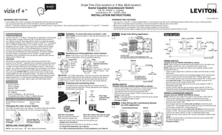
- 1. Scene Capable Incandescent Switch INSTALLATION INSTRUCTIONS WARNINGS AND CAUTIONS: WARNINGS AND CAUTIONS: INTRODUCTION Step 1 WARNING: TO AVOID FIRE SHOCK OR DEATH; TURN Step 4a Single Pole Wiring Application: Step 4b cont’d OFF POWER Terminal ® Screw marked White (WH) Vizia + (no LEDs) Switch not used BK 1 WH BK BK Hot (Black) Terminal ® ® Screw marked 2 Black Black (BK) Green Green Ground Ground 3 Terminal 4 RD YL/RD RD YL/RD Line Screw marked YL/RD RD Load Yellow/Red 120V (YL/RD) Terminal Screw marked ® Step 2 Identifying your wiring application (most common): Red (RD) White NOTE: Terminal Label: ® Use Terminal for 3-Way or More Applications Only. For Single-Pole Applications Do Not Remove This Label. Neutral (White) CAUTION: Single Pole 3-Way Switch WIRING SWITCH: 1. 1. (see Connect wires per WIRING DIAGRAM as follows: 2 2. 1 2 important instruction) NOTE: 1 3. 2. BK Hot (Black) 3 4. 3 4 3. Green NOTE: 4 5 4. Ground 5. RD YL/RD DO NOT USE Black Line 120VAC, 60Hz IMPORTANT : Load Use Terminal for 3-Way or More Applications On ly. For Single-Pole Applications , White Do Not Remove This Label. (note wire color) FEATURES Neutral (White) Step 3 Preparing and connecting wires: WIRING SWITCH: Connect wires per WIRING DIAGRAM as follows: (note wire color) WIRING COORDINATING REMOTE: 5/8" Connect wires per WIRING DIAGRAM as follows: ® Strip Gage (1.6 cm) NOTE: NOTE: (measure bare Tools needed to install your Switch Cut wire here) (if necessary) Proceed to Step 5. Step 4b 3-Way Wiring with Coordinating Remote (note color as above) (no LED) Application: Changing the color of your Switch: Coordinating Remote Switch (note color as above) Side Wire Connection Back Wire (either hole may be used) Terminal BK 1 BK Screw marked 1 solid wire copper only solid wire copper only Black (BK) 2 2 NOTE: Push in Line up tabs and 3 3 side at tab press in sides one Terminal straight (cut if necessary). Screw marked 4 4 Proceed to Step 5. to release at a time to attach Yellow/Red YL/RD RD YL/RD RD (YL/RD) 5 5 INSTALLING YOUR SWITCH Terminal Screw marked Red (RD) NOTE:
- 2. Step 4c 3-Way Wiring with Matching Remote Step 5 Testing your Switch prior to mounting in wall box: Step 8 cont’d OPERATION Push Pad (w/LEDs) Application: D) NOTE: Matching Switch Remote Switch NOTE: Push Pad (Default settings) Additional Neutral Wire Turn ON from OFF position: NOTE: 2 4 E) The switch is now installed in the network Locator BK Terminal BK NOTE: Turn OFF from ON position: Light 1 Screw 2 NOTE: marked 4 Black (BK) 3 3 1 5 Terminal YL/RD RD Screw YL/RD RD 5 Programmer/Controller Cleaning: DO NOT marked Cat. No. VRCPG Yellow/Red Terminal (YL/RD) Screw marked Red (RD) ADVANCED PROGRAMMING FEATURES Definition of Mode Matching Switch Remote (with LEDs) Switch NOTE: TROUBLESHOOTING section. Hot (Black) WH BK BK NOTE: Green Green Step 6 Switch Mounting: Ground Ground Black TURN OFF POWER AT CIRCUIT BREAKER OR FUSE. Excluding Switch from Z-Wave® Network: Locator LED Locator LED Option Setting Line YL/RD RD YL/RD Load NOTE: 120V ® White Step 7 Restore Power: Neutral (White) Installation is complete. A) ® TROUBLESHOOTING NOTE: must Step 8 Including Switch into Z-Wave Network: ® must B) NOTES: C) NOTE: WIRING MATCHING REMOTE (wall box with Line Hot connection): A) ® Connect wires per WIRING DIAGRAM as follows: Programmer/Controller Factory Default: Techline at 1-800-824-3005 or visit Leviton’s B) Cat. No. VRCPG website at www.ViziaRF+.com (note wire color) NOTE: DO NOT Gently press top of push pad (refer FCC COMPLIANCE STATEMENT C) WIRING SWITCH (wall box with Load connection): to figure) Connect wires per WIRING DIAGRAM as follows: Menu Button Center 1 ON Button CAUTION: OFF 2 ON OFF 3 ON OFF (note color as above) 4 ON NOTE: OFF LIMITED 5 YEAR WARRANTY AND EXCLUSIONS There are no other or