

Empfohlen
Weitere ähnliche Inhalte
Was ist angesagt?
Was ist angesagt? (20)
Andere mochten auch
Ähnlich wie Pump cavitation
Ähnlich wie Pump cavitation (20)
Kürzlich hochgeladen
Kürzlich hochgeladen (20)
Pump cavitation
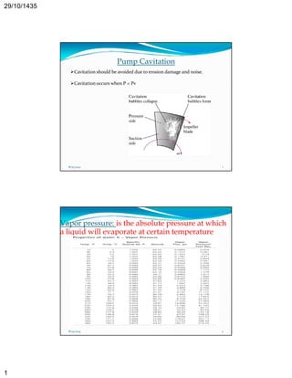
- 1. 29/10/1435 1 Pump Cavitation Cavitation should be avoided due to erosion damage and noise. Cavitation occurs when P < Pv 8/25/2014 1 Vapor pressure: is the absolute pressure at which a liquid will evaporate at certain temperature 8/25/2014 2
- 2. 29/10/1435 2 CAVITATION 8/25/2014 3 Concept of Cavitation Definitions: Some say when a pump makes a rattling or knocking sound along with vibrations, it is cavitating. Some call it slippage as the pump discharge pressure slips and flow becomes erratic. When cavitating, the pump not only fails to serve its basic purpose of pumping the liquid but also may experience internal damage, leakage from the seal and casing, bearing failure, etc. 8/25/2014 4
- 3. 29/10/1435 3 Meaning of the Term "Cavitation" in the Context of the Centrifugal Pump The term ‘‘cavitation’’ comes from the Latin word cavus, which means a hollow space or a cavity. Webster’s Dictionary defines the word ‘cavitation’ as the rapid formation and collapse of cavities in a flowing liquid in regions of very low pressure. 8/25/2014 5 Types Of Bubbles Formed In The Liquid Vapor bubbles Gas bubbles 8/25/2014 6
- 4. 29/10/1435 4 Vapor Bubbles Vapor bubbles are formed due to the vaporization of a process liquid that is being pumped. The cavitation condition induced by formation and collapse of vapor bubbles is commonly p y referred to as Vaporous Cavitation. Gas Bubbles Gas bubbles are formed due to the presence of dissolved gases in the liquid that is being pumped (generally air but may be any gas in the system). The cavitation condition induced by the formation and collapse of gas bubbles is commonly referred to as Gaseous Cavitation. Both types of bubbles are formed at a point inside the pump where the local static pressure is less than the vapor pressure of the liquid (vaporous cavitation) or saturation pressure of the gas (gaseous cavitation). 8/25/2014 7 Vaporous Cavitation It is the most common form of cavitation found in process plants. Generally it occurs due to insufficiency of the available NPSH or internal recirculation phenomenon. It generally manifests itself in the form of reduced pump performance, excessive noise and vibrations and wear of pump parts. The extent of the cavitation damage can range from a relatively minor amount of pitting after years of service to catastrophic failure in a relatively short period of time. 8/25/2014 8
- 5. 29/10/1435 5 Gaseous Cavitation Occurs when any gas (most commonly air) enters a centrifugal pump along with liquid. A centrifugal pump can handle air in the range of ½ % by volume. If the amount of air is increased to 6%, the pump starts cavitating. The cavitation condition is also referred to as Air binding. It seldom causes damage to the impeller or casing. The main effect of gaseous cavitation is loss of capacity. 8/25/2014 9 Mechanism of Cavitation 8/25/2014 10
- 6. 29/10/1435 6 Step One Formation of bubbles inside the liquid being pumped. The bubbles form inside the liquid when it vaporises i.e. phase change from liquid to vapor. But how does vaporization of the liquid occur during a pumping operation? Vaporization of any liquid inside a closed container can occur if either pressure on the liquid surface decreases such that it becomes equal to or less than the liquid vapor pressure at the operating temperature, or the temperature of the liquid rises, raising the vapor pressure such that it becomes equal to or greater than the operating pressure at the liquid surface. 8/25/2014 11 To understand vaporization, two important points to remember are: The static pressure and not the total pressure. The terms pressure and head have different meanings and they should not be confused So, the key concept is ‐ vapor bubbles form due to vaporization of the liquid being pumped when the local static pressure at any point inside the pump becomes equal to or less than the vapor pressure of the liquid at the pumping temperature. 8/25/2014 12
- 7. 29/10/1435 7 How does pressure reduction occur in a pump system? The reduction in local static pressure at any point inside the pump can occur under two conditions: The actual pressure drop in the external suction system is greater than that considered during design. As a result, the pressure available at pump suction is not sufficiently high enough to overcome the design pressure drop inside the pump. The actual pressure drop inside the pump is greater than that considered during g the pump p p design. g 8/25/2014 13 Pressure reduction in the external suction system of the pump 8/25/2014 14
- 8. 29/10/1435 8 Pressure reduction in the external suction system of the pump 8/25/2014 15 Dr.Ihab G.Adam 8/25/2014 16 Eng.Hisham Mohammed Khamys
- 9. 29/10/1435 9 Flow path of fluid inside the pump The internal suction system is comprised of the pump’s suction nozzle and impeller. Figures 5 and 6 depict the internal parts in detail. 8/25/2014 17 In Figure 7, it can be seen that the passage from the suction flange (point 2) to the impeller suction zone (point 3) and to the impeller eye (point 4) acts like a venturi i.e. there is gradual reduction in the cross‐section area. 8/25/2014 18
- 10. 29/10/1435 10 In the impeller, the point of minimum radius (eye) with reference to pump centerline is referred to as the “eye” of the impeller (Figure 8). Dr.Ihab G.Adam 8/25/2014 19 Eng.Hisham Mohammed Khamys How pressure reduction occurs as the fluid flows inside the pump? 8/25/2014 20
- 11. 29/10/1435 11 Step Two Growth of bubbles Unless there is no change in the operating conditions, new bubbles continue to formand old bubbles grow in size. The bubbles then get carried in the liquid as it flows from the impeller eye to the impeller exit tip along the vane trailing edge. Due to impeller rotating action, the bubbles attain very high velocity and eventually reach the regions of high pressure within the impeller where they start collapsing. The life cycle of a bubble has been estimated to be in the order of 0.003 seconds. 8/25/2014 21 Step Three Collapse of bubbles As the vapor bubbles move along the impeller vanes, the pressure around the bubbles begins to increase until a point is reached where the pressure on the outside of the bubble is greater than the pressure inside the bubble. The bubble collapses. The process is not an explosion but rather an implosion (inward bursting). Hundreds of bubbles collapse at approximately the same point on each impeller vane. Bubbles collapse non‐symmetrically such that the surrounding liquid p y y g q h f ll h d f l d rushes to fill the void forming a liquid micro jet. The micro jet subsequently ruptures the bubble with such force that a hammering action occurs. Bubble collapse pressures greater than 1 GPa (145x106 psi) have been reported. The highly localized hammering effect can pit the pump impeller. Dr.Ihab G.Adam 8/25/2014 22 Eng.Hisham Mohammed Khamys
- 12. 29/10/1435 12 The pitting effect 8/25/2014 23 Formation and collapse of a bubble 8/25/2014 24
- 13. 29/10/1435 13 Impeller Cavitation Regions 8/25/2014 25 General Symptoms of Cavitation and its Effects on Pump Performance and Pump Parts loud noises, vibrations and an unsteadily working pump. Fluctuations in flow and discharge pressure take place with a sudden and drastic reduction in head rise and pump capacity. Depending upon the size and quantum of the bubbles formed and the severity of their collapse, the pump faces problems ranging from a partial loss in capacity and head to total failure in pumping along with irreparable damages to the internal parts. It requires a lot of experience and thorough investigation of effects of cavitation on pump parts to clearly identify the type and root causes of cavitation. 8/25/2014 26
- 14. 29/10/1435 14 1-Reduction in capacity of the pump The formation of bubbles causes a volume increase decreasing the space available for the liquid and thus diminish pumping capacity. For example, when water changes state from liquid to gas its volume increases by approximately 1,700 times. If the bubbles get big enough at the eye of the impeller, the pump “chokes” i.e. loses all suction resulting in a total reduction in flow. The unequal and uneven formation and collapse of bubbles causes fluctuations in the flow and the pumping of liquid occurs in spurts. This symptom is common to all types of cavitations. 8/25/2014 27 2-Decrease in the head developed Bubbles unlike liquid are compressible. The head developed diminishes drastically because energy has to be expended to increase the velocity of the liquid used to fill up the cavities, as the bubbles collapse. As mentioned earlier, The Hydraulic Standards Institute defines cavitation as condition of 3 % drop in head developed across the pump. Like reduction in capacity, this symptom is also common to all types of cavitations. Thus, the hydraulic effect of a cavitating pump is that the pump performance drops off of its expected performance curve, referred to as break away, producing a lower than expected head and flow. p 8/25/2014 28
- 15. 29/10/1435 15 8/25/2014 29 3-Abnormal sound and vibrations It is movement of bubbles with very high velocities from low‐pressure area to a high‐pressure area and subsequent collapse that creates shockwaves producing abnormal sounds and vibrations. It has been estimated that during collapse of bubbles the pressures of the order of 10000 atm develops. The sound of cavitation can be described as similar to small hard particles or gravel rapidly striking or bouncing off the interior parts of a pump or valve. Various terms like rattling, knocking, crackling are used to describe the abnormal sounds. People can easily mistake cavitation for a bad bearing in a pump motor. To distinguish between the noise due to a bad bearing or cavitation, operate the g g p h fl h d f ll b d f pump with no flow. The disappearance of noise will be an indication of cavitation. 8/25/2014 30
- 16. 29/10/1435 16 Damage to pump parts Cavitation erosion or pitting 8/25/2014 31 Cavitation Damage on Impellers 8/25/2014 32
- 17. 29/10/1435 17 The two pictures are of the same area of a centrifugal pump impeller. The one on the left shows a typical cavitation pattern during flow. Bubbles are forming to the left and imploding at the impeller’s surface in the upper right. The picture on the right shows the actual damage caused by continuous implosion of bubbles in the same area. 8/25/2014 33 The picture shows damage at the low pressure side of the leading edge of an impeller vane due to suction cavitation. 8/25/2014 34
- 18. 29/10/1435 18 Net Positive Suction Head (NPSH) What is Net Positive Suction Head?? Net Positive Suction Head. NPSH is what the pump needs, the minimum requirement to perform its duties. Therefore, NPSH is what happens in the suction side of the pump, including what goes on in the eye of the impeller. NPSH takes into consideration the suction piping and connections, the elevation and absolute pressure of the fluid in the suction piping, the velocity of the fluid and the temperature. 8/25/2014 35 Net positive Suction Head (NPSH) Net positive Suction Head Available (NPSHA) Net positive Suction Head Required (NPSHR) 8/25/2014 36
- 19. 29/10/1435 19 8/25/2014 37 8/25/2014 38
- 20. 29/10/1435 20 Net positive Suction Head Available (NPSHA) The difference between the total suction head and the vapor pressure of the liquid at the suction flange. Calculating NPSHA of a piping system NPSHA = hsa – hvpa where: hsa = Total suction head head, absolute hvpa = Vapor pressure of liquid at the pumping temperature, absolute. 8/25/2014 39 hsa = hpsa + hss – hfs where: hpsa = suction surface pressure, absolute, on the surface of the liquid from which the pump takes its suction. This will be the atmospheric pressure, in the case of an open tank, or the absolute pressure above the liquid in a closed tank. hss = static suction head. In other words, the height of the liquid surface in the suction tank above or below the pump centerline. (Positive if the liquid level is above the pump, negative if the liquid level is below the pump). hfs = friction head loss, between the liquid surface in the suction tank and the suction flange of the pump. 8/25/2014 40
- 21. 29/10/1435 21 Net Positive Suction Head (NPSH) Net Positive Section Head and Cavitation (NPSH) NPSH Available Suction supply open to atmosphere with section lift. NPSHA =PB – (VP +LS +hf) Where PB= Barometric pressure in feet absolute. V V f th li id t i VP= Vapor pressure of the liquid at maximum pumping temperature, in feet absolute. Ls = Maximum static suction lift in feet. hf = Friction loss in feet in suction pipe at required capacity. 8/25/2014 41 Net Positive Suction Head (NPSH) Net Positive Section Head and Cavitation (NPSH) NPSH Available Suction supply open to atmosphere with section head. NPSHA =PB + LH ‐ (VP +hf) Where PB= Barometric pressure in feet absolute. V V f th li id t i VP= Vapor pressure of the liquid at maximum pumping temperature, in feet absolute. LH = Minimum static suction head in feet. hf = Friction loss in feet in suction pipe at required capacity. 8/25/2014 42
- 22. 29/10/1435 22 Net Positive Suction Head (NPSH) Net Positive Section Head and Cavitation (NPSH) NPSH Available Closed suction supply with suction head. NPSHA =P + LH ‐ (VP +hf) Where P = Pressure on surface of liquid in closed suction tank, in feet absolute. VP= Vapor pressure of the liquid at maximum pumping temperature, in feet absolute. LH = Minimum static suction head in feet. hf = Friction loss in feet in suction pipe at required capacity. 8/25/2014 43 Net Positive Suction Head (NPSH) Net Positive Section Head and Cavitation (NPSH) NPSH Available Closed suction supply with suction lift. NPSHA = P ‐ (VP ‐ LS +hf) Where P = Pressure on surface of liquid in closed suction tank, in feet absolute. VP= Vapor pressure of the liquid at maximum pumping temperature, in feet absolute. Ls = Maximum static suction lift in feet. hf = Friction loss in feet in suction pipe at required capacity. 8/25/2014 44
- 23. 29/10/1435 23 Net Positive Suction Head Required (NPSHR) The reduction in total head as the liquid enters the pump. 8/25/2014 45 8/25/2014 46
- 24. 29/10/1435 24 8/25/2014 47 NPSH testing Two procedures are used for NPSHR testing as follows:‐ Establishing a constant NPSHA and then varying the pump flow by means of a discharge control valve until a predetermined amount of deterioration (usually 3 percent) in the pump discharge head performance is observed 8/25/2014 48
- 25. 29/10/1435 25 An alternate procedure is to hold capacity constant while the NPSH available is reduced by either throttling or changing the vacuum on the pump suction 8/25/2014 49 Methods of reducing NPSHA 1‐Valve suppression In the valve suppression method of testing, a valve, located in the suction line leading to the pump, is used to reduce the suction pressure by throttling, thus creating varying NPSHA conditions. 8/25/2014 50
- 26. 29/10/1435 26 2‐Vacuum method An alternate to valve suppression testing is to create a vacuum on the suction side of the pump . This is done by using a tank or reservoir in which the pressure above the liquid is reduced bymeans of an ejector or a vacuum pump. 8/25/2014 51 The objective of all these testing methods is to establish the NPSH requirements, at various flow rates, for a given impeller‐casing combination and to construct an NPSHr versus flow capacity curve. 8/25/2014 52
- 27. 29/10/1435 27 Suction specific speed A dimensionless rating number which indicates the relative ability of centrifugal pumps to operate under conditions of low available net positive suction head. where: S = suction specific speed N = rotative speed, in revolutions perminute Q = capacity, at best efficiency, in gallons per minute hsv = net positive suction head required by maximum diameter impeller at best efficiency, in feet Depending on impeller design design, suction specific speeds will vary in numerical value from below 4,000 to above 11,000 with the higher values indicating lower net positive suction head requirements. 8/25/2014 53 General rule to avoid cavitation NPSHa > NPSHr + 3 ft or more safety margin 8/25/2014 54
- 28. 29/10/1435 28 Net Positive Suction Head (NPSH) NPSH margin According to the Hydraulic Institute, NPSH margin is required above the NPSHR f h h f f of the pump to suppress incipient cavitation. The amount of margin is a function of Suction Energy and the critical nature of the application as follows: NPSHMargin Ratio (NPSHA/NPSHR) Low 1.1 ‐ 1.3 High 1.2 ‐ 1.7 Very y High g 1.7 7 ‐ 2.5 5 8/25/2014 55 Pump Cavitation and NPSH Cavitation should be avoided due to erosion damage and noise. Cavitation occurs when P < Pv Net positive suction head NPSH required curves are created through systematic testing over a range of flow rates V. 8/25/2014 56
- 29. 29/10/1435 29 Net Positive Suction Head (NPSH) Cavitation If the pump operates to the right of point A, A then the required suction head is greater than the available suction head. This means that vapour bubbles will occur in the suction pipe. While Operation to the left of point A means that vapour bubbles will not form, and so Cavitations will not be a problem. bl 8/25/2014 57 If the available NPSH is not greater than that required by the pump, the following serious problems can result :‐ 1. A marked reduction in head and capacity (the energy expended in accelerating the liquid to high velocity in filling q g y g the void left by the bubble is a loss, and causes the drop in head, while the loss in capacity is the result of pumping a mixture of vapor and liquid instead of liquid). 2. Excessive vibration can occur when sections of the impeller are handling vapor and the other sections handling liquid. 3. Probably the most serious problem is pitting and erosion of the pump parts, resulting in reduced life. 4. Erratic flow rate with spurts of liquid being thrown from the discharge pipe. 8/25/2014 58
- 30. 29/10/1435 30 The solid line curves represent a condition of adequate NPSHa whereas the dotted lines depict the condition of inadequate NPSHa i.e. the condition of cavitation. 8/25/2014 59 Impeller damaged by cavitation 8/25/2014 60
- 31. 29/10/1435 31 8/25/2014 61 8/25/2014 62
- 32. 29/10/1435 32 Detecting a low NPSHA problem A centrifugal pump in the field that is cavitating often will sound as if it is pumping rocks, and frequently the discharge pressure will pulsate. A simple way to determine if the problem is a flow‐induced NPSH problem is to slowly shut down on the discharge block valve. If the problem is flow‐induced, the noise and the pulsations should go away as the flow is reduced through the pump. pump 8/25/2014 63 Net Positive Suction Head (NPSH) How to stop vaporization Cavitation By increasing the suction head • Raise the liquid level in the tank • Elevate the supply tank. . • Reduce the piping losses. •Install a booster pump . • Pressurize the tank. • Be sure the tank vent is open and not obstructed. • Some vents can freeze in cold weather. 8/25/2014 64
- 33. 29/10/1435 33 Net Positive Suction Head (NPSH) How to stop vaporization Cavitation By lowering the fluid inlet temperature • Injecting a small amount of cooler fluid at the suction is often practical. • Insulate the suction piping from the sun's rays. • Be careful of discharge re‐circulation and vent lines re‐circulated to the pump suction; they can heat up the suction fluid. 8/25/2014 65 Net Positive Suction Head (NPSH) How to stop vaporization Cavitation By decrease the fluid velocity •Remove obstructions in the suction piping. • Reduce the speed of the pump. • Reduce the capacity of the pump. • Do not install an elbow too close to the pump suction. 8/25/2014 66
- 34. 29/10/1435 34 Net Positive Suction Head (NPSH) How to stop vaporization Cavitation By reducing the net positive suction head required (NPSHR) • Use a double suction pump. Double suction designs can reduce the net positive suction head required (NPSHR) by as much as 27%, • Use a lower speed pump. • Use a pump with a larger impeller eye opening. • Use several smaller pumps. Three half‐capacity pumps can be cheaper than one large pump plus a spare. This will also conserve energy at lighter loads. 8/25/2014 67 8/25/2014 68 Pump fitted with inducer
- 35. 29/10/1435 35 Pump Priming * Why you must prime a centrifugal pump ? To remove air from the pump cavities and the suction piping, the pump must develop enough head to equal the equivalent of one bar pressure which extends from the earth’s atmosphere. Since the weight of water is approximately 8000 times that of air, the centrifugal pump can produce only 1/8000 of its rated liquid pressure. another explanation:‐ A centrifugal pump is a rotodynamic pump 69 pump. As head = pressure / sp.Weight of the pumped liquid. the pressure difference created with air will be only around 1/800 times that with water due to the density difference. Priming Process “ It is a process of air /vapor removal from pump suction and casing by filling it up with liquid ”. 70 .
- 36. 29/10/1435 36 Positive displacement pumps priming When pumping low‐viscosity liquids , a foot valve may be used to help keep the pump primed. Alternately, a vacuum device may be used to prime the pump. When handling liquids of higher viscosity, foot 71 g q g y, valves are usually not required because liquid is retained in the clearances and acts as a seal when the pump is restarted. C.P Priming Methods Install a foot valve in the suction piping. Evacuate the air in the system with a positive displacement priming pump. Fill the pump with liquid prior to starting it using a hose or a small pot. Make a bypass line from discharge line. Convert the application to a self priming pump that maintains a reservoir of liquid at its suction. 72
- 37. 29/10/1435 37 Priming Chambers 1‐ Single Chamber tank 73 2‐ Double Chamber Tank: 74
- 38. 29/10/1435 38 Testing for Air in Centrifugal Pumps The presence of only small quantities of air can result in considerable reduction in capacity, since only 2% free air will cause a 10% reduction in capacity, and 4% free air will reduce the capacity by 43.5%. Entrained air is one of the most frequent causes of shaft breakage. It also may cause the pump to lose its prime and greatly accelerate corrosion. If air is present, the pump is likely to operate with a certain amount of internal noise. This noise can be described as a "gravel noise" 75 We will assume that calculations have already been made to assure that the NPSH available is greater than that required by the pump, (the noise is not a result of cavitation). When the source of suction supply is above the centerline of the pump, a check for air leaks can be made by collecting a sample in a "bubble bottle“. Since the pressure at the suction chamber of the pump is above atmospheric pressure, a valve can 76 p p , be installed in one of the tapped openings at the high point in the chamber and liquid can be fed into the "bubble bottle." The presence of air or vapor will show itself in the "bubble bottle."
- 39. 29/10/1435 39 Self Priming Pumps Self‐priming pumps overcomes the air binding problem by mixing air with water to create a pumpable fluid with pumping properties much like those of regular water . recirculating water within the pump on priming cycle is the main operation concept. This type of pump differs from a standard centrifugal pump in that it has a ater reser oir water reservoir built into the unit may be above the impeller or in front of the impeller. 77 a charge of liquid sufficient to prime the pump must be retained in the casing (Fig. A) When the pump starts, the rotating impeller creates a partial vacuum ; air from the suction piping is drawn into this vacuum and is entrained in the liquid drawn from the priming chamber (Fig. B), then the priming cycle starts. This cycle is repeated until all Fig. A 78 of the air from the suction piping has been expelled and replaced by pumpage and the prime has been established (Fig. C). Fig. B Fig. C
- 40. 29/10/1435 40 Self Priming pumps Piping System Considerations Insure that adequate liquid is retained In the priming chamber. The static lift and suction piping should be minimized to keep priming time to a minimum. Keep All connections in the suction piping should be leak‐free as air could be sucked in. 79 A priming bypass line should be installed. The suction piping 80 p p g should be designed such that no high points are created
- 41. 29/10/1435 41 Priming Time Calculation 1. Select . the correct size and speed pump 2. Calculate the NPSH Available for the system. NPSHA = P‐(Ls + Vp + hf) P = Pressure on surface of liquid in feet absolute Ls= Maximum static lift in feet Vp= Vapor pressure of the liquid at maximum pumping temperature in feet absolute 81 absolute. hf = Suction pipe friction loss in feet at the required capacity. 3.Determine the effective static lift. Les = Ls x Sp. Gr. 4. Enter the priming time curve at the effective static lift then downward to the bottom coordinate to determine the priming time (PTLes ) to achieve the given lift. 5. insert the priming time into the following formula to calculate the total system priming time: PTT = Total system priming time. PTLES = Priming time in seconds for the effective static lift SPL = Total suction pipe l th i f t 82 length in feet. Dp = Nominal pipe diameter. Ds = Nominal pump suction diameter.