[IJET-V1I4P12] Authors :Nang Khin Su Yee, Theingi, Kyaw Thiha
Clips
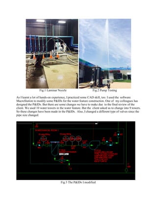
1. Fig.1 Laminar Nozzle Fig.2 Pump Testing
As I learnt a lot of hands-on experience, I practiced some CAD skill, too. I used the software
MacroStation to modify some P&IDs for the water feature construction. One of my colleagues has
designed the P&IDs. But there are some changes we have to make due to the final review of the
client. We used 10 water towers in the water feature. But the client asked us to change into 9 towers.
So these changes have been made in the P&IDs. Also, I changed a different type of valves since the
pipe size changed.
Fig.3 The P&IDs I modified
2. I drew the P&ID of the Sand Filter system according to the Sand Filter manufacturer. The white
line is for the instrument air while the green line is water pipe. The PLC controls the solenoid
valves to supply instrument air to pneumatic valves in order to adjust the flow rates of the Sand
Filter. The pneumatic 3-way valves provide alternative routes for water to backwash the Sand Filter.
Fig.4 Sand Filter P&ID
I drew a P&ID for the equipment room and the two basins. The design schematic hasn’t been
finalized yet, so I didn’t have much information for the whole water system. Instead, I drew the
water treatment system combining filtration system, Brominator system, ozonator system and
water quality monitor system. I also drew the air compression loops to supply the water shooters.
4. After finished the P&ID, I made the pump selections according to the water system in the P&IDs. I
used the Equivalent Length Method to calculate the head losses of each device in the flow. Then I
summed all the losses together to get the pump head. I calculated the NPSHA (Available Net
Pressure Suction Head) as well. After calculations, I selected the pump models using the
Manufacturer’s online selection software.
Fig.7 Pump Selection Sheet
Fig.8 Online Pump Selection Software