
Empfohlen
Empfohlen
Weitere ähnliche Inhalte
Was ist angesagt?
Was ist angesagt? (20)
Ähnlich wie Theory for Welded connection.pdf
Ähnlich wie Theory for Welded connection.pdf (20)
Kürzlich hochgeladen
Kürzlich hochgeladen (20)
Theory for Welded connection.pdf
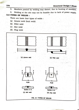
- 1. , 134 Structural Design-I (Steel) 5. Members jointed by welding may distort, due to heating of mem~ers. 6. Welding at the site may not be feasible due to lack of power supply. 3.3 TYPES OF WELDS : ' There are basic four types-of welds : (a) Groove weld (butt weld) (b) ~llet weld -(c) . Slot weld _ (d) · P~ug weld I (a) ·g~ weld -1- I ■ I Section A-A (c) slot weld t t . ' (b) Fillet weld - PLAN I I I Sectlon A-A (d) plug weld FIG. 3.1 TYPES OF WELDS
- 2. p _) welded Connections 135 Each type o~ weld has its own advantage and may be selected depending upon the situation. Fillet welds are suitable for lap Joints and T-Joints. Groove welds are suitable for butt Joint, comer Joint and edge Joints. It has been found that, Fillet welds are used 80% Groove welds are used 15% Slot and plug welds are used 5% in structural engineering applications. {a) Groove welds : • Groove welds are normally used for butt joints._ • It is used to connect two members that are aligned in the same plane. . • The grooves have a slope of 30° - 60°~ Various types of groove welds are shown in fig. 3.2. weld TT symbol - V ~ g I I I ' ' l % (a) Square butt (b) Single V-butt - (a) Doubl~v butt " 8 0 ·v' I ' l I ' I , ( . (d) Single-u butt (e) Double u-butt (f) Single bevel butt K p g I t 1 , I I ' (g) Double bevel butt (h) Single J-butt (I) Double J-butt FIG. 3.2 TYPES OF GROOVE WELDS (BUTT WELDS) {b) Fillet Weld : Fillet welds are widely used in structural engineering application d · I Th s • ue to their economy and ease cd app tcation. f;Y are approxtmatel · Y t~angular in cross section.
- 3. ~ 136 Structural Design-I (lteet) Fillet weld joints are most suitable in the following cases : • 1vo elements meeting at angle • Between angle and gusset plate • Between flange and web plates • Beam bearing :plates • Between bracket and column • Between beam and column • Between column and base plate • For slotted connection, etc. Typical us~s of fillet welds are shown below. (a) angle and guaet: plate (b) colun-braeket ____. (c) beam to beam connection weld H (d) Slotted connection (e) Beam bearing plate (d) column base plate (g) aunt-up eectlon (g) pipe connection FIG. 3.3 TYPICAL USES OF FILLET WELD . !
- 4. ' wt;;iu-- ~ ..---:: I 3.4 WELD SYMBOLS : The standard weld symb 1 o s used on dr wi , are shown In fig. 3.4. a ngs ,or different types of welds Types of weld Fillet Concave Butt weld Seam Weld Slot Weld Fillet Square V I Bevel I U-butt J-butt I Flat all or butt butt butt V around plug -- ~I & 11 V V y ~ V ~ 0 I r7 FIG. 3.4 WELD SYMBOLS General notation of welding : field weld symbol other aide I Referer.ce One T r.:--r~-----a .arrow side I 8 r .so c100> weld all around symbol FIG. 3.5 NOTATIONS OF WELDING . • The 'siµe' below the arrow is called the arrow side and the side above the arrow is called the other side. • A circle at the kink indic~tes a ~eld ~11 around and a vertical line and triangular pennant at the kink shows a field weld. ' If the weld Is on arrow side, the weld symbol Is shown below the arrow line aild vtce-versa. weld symbol on arrow side Is Inverted. ' The size of weld Is shown near the fork on the horizontal line. ' The surface condition Is shown by a convex or horizontal line (con- tour symbol) ' There are different types of contours of the weld surface and they are : flush finish, convex or concave finish. Different finishes are grtnd- tng or machining etc. ,Desi-1 St - e ,.,
- 5. 138 • Structural Design-I (S~ ';rhe length and pitch of the weld are shown after the weld syn1i;- Pttch of weld is shown in the bracket. I. • Some remarks like specification, process or other reference are sboWn within the fork lines. The use of weld symbols ts illustrated as under in fig. 3.6. r • (a)_ _; (b) 8mm _+-_.. weld 6 6 mm fillet weld on same side 6 mm fillet weld on the other side (field welding) 8 150 70 150 6 50(100)50(100) 150 70 150 70 150 · 70 (c) 6 mm fillet weld on arrow ~tde wtth lengti;°of weld 50 mm and pitch 100 mm. · - - I I I I I 200
- 6. telded Connection• 139 r--:.:~r-< 8hop weld FIG. 3.6 ILLUSTRATIONS OF WELD SYMBOLS • 8 mm fillet weld on other side with length of weld 70 mm and pitch 150 mm (shop welding) 6 mm fillet weld all around having total length of weld equal to 200 mm. 38 mm diameter plug weld with flush finish and shop welding. 3.5 PROPERTIES OF FILLET WELD : (IS : 800 - 2007 cl.10.5, Page 78) thn>at thlclcnea A fuston zone toe FIG. 3.7 FILLET WELD ft ft ft (a) Concave (b) Convex (c) Mitre •-~z• ~-throat thickn... Fig. 3.7.1 Types of fillet Welds
- 7. 140 AB and BC = Two legs of weld BD = Throat thickness Minimu~ of AB and BC = size of weld B = root of fillet weld C = Toe of fillet ~eld AC = Face of the weld Structural Design-I (Steel) .......... (a)- Size of weld (S) : • The size of normal fillet weld shall be taken as the minimum _ weld leg size. . • The size of fillet weld should not be less than 3 mm, nor more·than the thickness of the thinner part joined. The minimum size of the first run or a ·single run fillet weld shall be as given tn__table 3.1. .. . Table 3.1 Minimum size of first run or, of a single- run ~et weld. Thickness of thicker part Minimum size -- ►.; - over, mm up to and in.eluding, mm . ~ -~-- mm - - ·- , . .. ,. . - ·- 10 3 - 10 20 5 - - .. . - 20 32 6 32 5,0 - 8 for first run . - - 1O for minimum size of ~ - -- • When the minimum size of the fillet_ vield ·given in the table ts greater -· - f weld than the thickness ·of the .thin~er part, the minimum -size 0 should be equal to the thickness of the thinner part. • Maximum ftllet weld alze along edges : . stze (1) Along the edge of the plate, less t~an 6 mm thick, the maxi~urn of weld ts equal to the thickn~ss of the plate.
- 8. r tetded connections 141 ~ Desirable · (a) J;m Acceptable becoUN of full throot thlckneaa (b) Not acceptabfe becauae of reduced throat thickness (c) FIG. 3.8 FULL SIZE FILLET WELD APPLIED TO THE EDGE OF A PLATE (2) Where the fillet weld ts applied to the square edge of a plate of thick- ness greater than 6 mm, size of weld should be atleast 1.5 mm less than the edge thickness Fig. 3.9 (a). _. · V4 /aDIClfled elze _ · l r--~-====t' t -..-..-_____, (a) (b) . . FIG. 3.9 FILLET WELD ON SQUARE EDGE OF A PLATE OR ROUND TOE (3) Where the fillet weld ts applied to the rounded toe of the rolled sec- tion, the size of the weld should not exceed 3/4 of the thickness of the section at the toe. Fig. 3.9 (b). lb) Effective throat thickness- : The effective throat thickness of a fillet weld ts the shortest distance from lhe root to the face of the weld. . . The effective throat thickness of a fillet weld shall not be less than 3 mm atld shall not exceed 0.7 a, where 'a' ts the size of weld in mm. Fig. 3.10 (a). If fillet weld ts having unequal legs, the effective throat thickness shall be torn ab O Cb) Puted as ¼ = J 2 • Fig. 3.1 . a2 +b .
- 9. -142 root r a / / / / (a) Equal lege · toe Structural Dealgn-J ·(~teel) I a / L,,,, (b) unequal lega FIG. 3.10 EFFECTIVE THRO~T THICKNESS OF FILLET WELD For fillet welds joining faces inclined to eachother, the effe_ ctive throat thick- ness shall be taken as follows : .Effective throat thickness = K x Size of weld Where, - - K = ~'?nstant depending upon the -angle between fusion faces. = 0.7, for 60°· to 90° (code, table - 22) S = Size of weld 1tt = o.7 s 1 (c) End returns : (IS : 800 - 2007. cl.10.5,1.1) The fillet welds terminating at the ends or sides of parts should be re· turned continuously ·around the corners for a distance of not less than twice the size of the weld. i.e., end return ~ 2 S, S = Size of weld
- 10. wetded connections 143 end etum~2a FIG. 3.11 END RETURN (d) overlap : flllet weld In case of lap Joints, the mini- mum lap should not be less than four umes the thickness of the thinner part Joined or 40 mm whichever is more. (e) Effective length or area of weld: t L ~ 4t or '40mm FIG. 3.12 OVERLAP • The effective length of fillet weld shall be taken as only that length which ts of specified size and required throat thickness. • Minimum length : Minimum length of fillet weld = 4 x size of the weld • In practice, the actual length of weld is made of the effecttve length shown tn drawing + (2 x Weld size) • Intermittent Weld : Fillet welds can be provided continuously or intermittently. ·Effective length of intermittent weld shall be taken as larger of, (i) 4 x size of weld (ii) 40 mm • The clear spacing between the effective lengths of intermittent fillet weld shall not exceed, (i) 12 t, for compressi.on (ti) 16 t, for tension and in no case ft shall exceed 200 mm. Where, t = thickness of thinner plate • The intermittent welds shall not be used in positions subject to dynamic, repetitive and alternating stresses.
- 11. 1fl:P: Structural Design-I (Steel) -3.6 STRESSES IN FILLET WELDS : Design strength of fillet weld. f°wd = fwr/Ymw ···· ···· ···· (3 . l) Where, IS : 800 - 2007 cl.10.5.7.1 page-79 fu fwn = J3 fu = Smaller of the ultimate stress of the weld or of the parent metal Yinw = P~al -safety;,: !~ctor (code ·table 5) ~ - · - ~ -_ = 1.25 for shop welding = 1.50 for field welding • For -shop welding : ~~ -= f~ / {.Js X Ymw} =:= 410 / (J'3 X 1.25) = 189 N/mm~ ,. - ;: - - : ;_,, ;:-_ -;_:. ~ -,. -'· ;..,., '. ... .. -- - : _. .. fw;;;~:~)•.·..·,,;,l'~~?{./::;~~tL/~_- .. ~----- - '7---:: ,.v_ ~- .. ~.::-- -- • •• For ,field wel~g. : - ~--JS-=-158 N/mm~ -- < ;_<~-:~-t:-, ::~--t-.t-~~~ :_/'. >~ -,:._, ·>J•: --- • Stresses due to individual 'ftircei·- -r·- -~3 -'.: - ~·- -- - When subjected to .~ither C<?mpressive _ or tei{sift{-::?r_ -iiliei~r -force·. the stress in the weld is given by -: : - -- -- =- _ ; - --" - -~: ·=. ~- - p fa or q = lw · tt _ -(3.2) Where, fa = normal stress due to axial force q = shear stress -(N/mm2) _ P = force transmitted '(N) tt = throat thickness (mm) = 0.7 S 'w = effective length of weld (mm) IS :-800 - 2007 P. 79 er. 10.5.9
- 12. welded Connections Design strength of weld is , p = lw·tt fwd 3.7 COMBINATION OF STRESSES Fillet welds : 145 .. .. .. .. ... . (3.3) (Dec. 2011) Fillet welds, when subjected to a combination of normal and shear stress. the equivalent stress fe shall satisfy the following. fe = Jr; + 3q 2 ....... . .... (3.4) fu < - .J3 Ymw Where, IS : 800 - 2007 cl. 10.5. 10 P.80 fa = normal stress, compression or tension. due to axial force or bend- ing moment. q = shear stress 3.8 GROOVE WELDS : (Dec. 2011) The effective throat thickness of a complete penetration groove weld is taken as the thickness of the thinner part joined. Fig. 3.13 (a). (b). The effective throat thickness of a partial penetration joint weld is taken 5 , as 8 x thickness of the thinner member Joined. Fig. 3.13 (c). (d). t2 41 t1 1 t ~ t I tt=t1 lt =t - (a) Co,JT1pl.,te Penetration (a) Complete Penetration l ti 9ft, I ti 8ft, f 5 tt--st 5 lt -"Bt (c) Partial Penetration (d) Partial Penetration ( Incomplete) FIG. 3.13 EFFECTIVE THROAT THICKNESS FOR GROOVE WELDS S !ruc_Desi-1 Steel 2012 19 • - I~
- 13. 146 Structural.l)eslgn.1 (S --------------:--:-:-=--::.-::-=:~=-:=--=:;--:;:-:~::--=-~=-....::tee1) As per IS : BOO_ 2007 (cl.10.5.7.1.2) groove welds (butt welds) sh~ treated as parent metal with a thickness equal to throat thickness, and the ..stresses shall not exceed those permitted in the parent metal. e . • For tension or compression : Design strength of weld, Tdw = fw · tt · fy/Ymw fy = Smaller of the yield stress of the weld ••. · ..•..•.. (3,5) and the parent metal. • For shear : vdw = 1w. ¼. f.,w/CJ3 X Ymwl Where, Vdw: = Design strength of weld in shear. 3.9 Eccentrically loaded connections : For shop welding Ymw = 1.25 For site welding Ymw = 1.50 •••• ••·· .... (3.6) The welded joints subjected to ecce_ntric .load ~re two types (a) Eccentric load causing twisting· moment (b) Eccentric load causing bending momel}-t (a) Eccentric load causing twisting moment : The e.g. of group of the weld_lies in· the plane of line of a:ction of the ap- plied load. Load P will cause direct shear and twisting moment in the weld. G = Centroid of weld x and Y are the co-ordinates of cen- troid of the weld. B is the critical point on weld, x and y are co-ordinates of the critical weld point. r = [x2 + v2 z y D ,_ y ----~ r/ I / • -h?-~ · 1G . Z I C ~ I y FIG. 3.14 p t
- 14. wetded Connections stress due to direct shear, p Pd= - N/mm lw stress due to torsion (Twisting moment) Txr pt= Ip Where, T = Twisting moment r = distance of critical point from G. IP = Polar M.I. of weld. resultant stress, R = .JpJ + Pf +2 Pd· Pt· cos0 N/mm Weld resistance = 4 · fwd R = tt. fwd (b) Eccentric load causing bending moment : 147 ............ (3. 7) .... .... .... (3.8) (3.9) The e.g. of group of the weld does not lie in the plane of the line of action of the applied load. The load P will cause direct shear and bending moment in the weld. • r a.. l p Flllet nld FIG. 3.15 H-H- 1t 1t t---•column flange la.. J I
- 15. L 148 Structural »e.lp-1 (Steel) (1) P111et Welda : • Load Direct shear stress = effectivearea of weld p q = 2 · lw · f:t Moment • bending stress = Secttonmodulus M M fa=z=T·y M = p x e 6M or fa = 2 . tt . z! • Resultant stress. /2 2 f'_ re= ~fa +q < ~ (2) Groove welds : . • Direct shear stress. p q -=:= d . t Wh~~e. d = depth of p~ t = thickness of plate • Bending stress, M M ra = z = T. y 6M or fa= td2 • fy f /f2 + 3q2 < - Resultant stress, e = iJ a Ymo