Automated irrigation system based on soil moisture using arduino
•
5 gefällt mir•3,054 views

Automated irrigation system based on soil moisture using arduino More Details: Contact me 9982228229 www.roofurja.com vishalnagarcool.blogspot.com https://www.youtube.com/watch?v=utHRD4B8BxQ

Empfohlen
Empfohlen
Weitere ähnliche Inhalte
Was ist angesagt?
Was ist angesagt? (20)
Ähnlich wie Automated irrigation system based on soil moisture using arduino
Ähnlich wie Automated irrigation system based on soil moisture using arduino (20)
Kürzlich hochgeladen
Kürzlich hochgeladen (20)
Automated irrigation system based on soil moisture using arduino
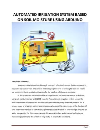
- 1. Page 1 AUTOMATED IRRIGATION SYSTEM BASED ON SOIL MOISTURE USING ARDUINO Executive Summary Modern society is interlinked through a network of not only people, but their respective electronic devices as well. The devices permeate people’s lives so thoroughly that it is rare to see someone without an electronic device, be it a watch, a cellphone, a computer. In this project an automation of farm irrigation and soil moisture control by Arduino using soil moisture sensor and L293D module. This automatic irrigation system senses the moisture content of the soil and automatically switches the pump when the power is on. A proper usage of irrigation system is very necessary because the main reason is the shortage of land reserved water due to lack of rain, spontaneous use of water as a result large amounts of water goes waste. For this reason, we use this automatic plant watering and soil moisture monitoring system and this system is very useful in all climatic conditions.
- 2. Page 2 India is the agriculture based country. Our most of peoples are completely depended on the agricultural harvesting. Agriculture is a source of employment of majority Indians and has great impact on the economy of the country. In dry areas or in case of lacking rainfall, irrigation becomes difficult. So, it needs to be automated for proper watering a plant and handled remotely by farmer. When soil goes dry pump will start watering. The aim of the implementation is to reduce water use and automatic irrigation can be used for save time and low power monitor device. Acknowledgments: The scope for this project was wide and the possibilities far. Without the support of the sponsors, facilitator, and others, this project could not have been completed. Specifically, the team would like to thank: ● Vishal nagar advice and their continuing support for a developing project. ● Our families for their support through a time-consuming semester.
- 3. Page 3 Table of Contents Chapter 1 - Introduction and Background 3 Introduction 3 Background 3 Chapter 2 - Solution Exploration and Selection 6 Section 1 - FAST Diagram 7 Chapter 3 - Technical Work Performed 8 Section 1 - Hardware Design Efforts 8 Section 2 - Hardware Implementation 9 Section 3 - Software Design Requirements 17 Section 4 - Software Implementation 17 Subsection 1 - Microcontroller Program 18 Chapter 4 - Benefits 23 Chapter 5 - Conclusions 23
- 4. Page 4 Chapter 1 – Introduction and background Introduction The main aim of this project was to provide water to the plants or gardening automatically using microcontroller (Arduino Uno). We can automatically watering the plants when we are going on vacation or don’t we have to bother my neighbors, Sometimes the Neighbors do too much of watering and the plants end up dying anyway. There are timer based devices available in India which waters the soil on set interval. They do not sense the soil moisture and the ambient temperature to know if the soil actually needs watering or not. Assimilation is that the artificial application of water to the land or soil It is used to assist in the growing of agricultural crops, maintenance of landscapes, and re vegetation of disturbed soils in dry areas and during periods of inadequate rainfall. When a zone comes on, the water flows through the lateral lines and ultimately finally ends up at the irrigation electrode (drip) or mechanical device heads. Several sprinklers have pipe thread inlets on the lowest of them that permits a fitting and also the pipe to be connected to them. The sprinklers are usually used in the top of the head flush with the ground surface. As the method of dripping will reduce huge water losses it became a popular method by reducing the labor cost and increasing the yields. When the components are activated, all the components will read and gives the output signal to the controller, and the information will be displayed to the user (farmer). The sensor readings are analog in nature so the ADC pin in the controller will convert the analog signals into digital format. Then the controller will access information and when the motors are turned On/Off it will be displayed on the LCD Panel, and serial monitor windows. There are many systems are available to water savings in various crops, from basic ones to more technologically advanced ones. For instance, in one system plant watering status was monitored and irrigation scheduled based on temperature presents in soil content of the plant.
- 5. Page 5 Background On the hardware side, there are a number of products currently on the market that can perform some of the requirements of this project. The Automatic Sprinkle System is the best example . The Automatic Sprinkle System is a Connect microcontroller with a built-in Bluetooth module. It is able to perform many of projects functions, such as communicating with wired and wireless sensors, transmitting information to an Android device via Bluetooth, and storing data to an SD card. However, the main problem with this solution, along with many others like it, is that the microcontroller must be programmed to perform this operation. This makes the microcontroller an impossible solution for users who don’t know how to program, and an impractical solution for those that can program, but don’t want to. A better product would already have the code pre-compiled, the input ports clearly labeled, and require little to no setup from the user.
- 6. Page 6 Chapter 2 – Solution Exploration and Selection Section 1 – FAST Diagram The complete system design with its logical components is more easily presented by utilizing the FAST diagram. The FAST diagram is able to take what could possibly be a complicated project and break it down to an easy to follow format. Having a recognizable format such as this enables the designer to best focus their efforts on what is needed in the final product. The FAST diagram developed by the team is shown below. There are two functional components in this project. They are the moisture sensors module and the motor driver for motor pump. Thus the Arduino Board is programmed using the Arduino IDE software. The function of the moisture sensor is to sense the temperature content present in the soil, and also it measure moisture level in the soil. The motor driver interrupts the signal to, water pump supplies water to the plants. This project uses microcontroller Arduino Uno board to controls the motor and monitor soil moisture. Follow the schematic to connect the Arduino to the motor driver, and the driver to the water pump. The motor can be driven by a 5 volt battery, we can also supplies power from external source or from Arduino board. The Arduino Board is programmed using the Arduino IDE software. Figure 2.1 - Fast Diagram
- 7. Page 7 The Sensor Interface can be broken down into three main components: The LCD, the microcontroller, and the sensors which it communicates with. The LCD and microcontroller are essentially the support behind the sensors to collect, store, transfer and display data. Designing more advanced sensors was beyond the scope of this project, so the LCD and microcontroller became the areas of focus. The Sensor Interface was designed to accept a wide variety of sensors, analog, digital, wired and IC. Any of the sensors can also be connected to another Bluetooth module to allow a wide variety of wireless sensors to communicate with the central Sensor Interface microcontroller. Section 2 – Objectives of the Project Monitor the moisture content of the soil using a soil moisture sensor and the water level of the tank using a float switch. Turn the motor ON when the soil moisture falls below a certain reference value and if there is enough water in the tank. Display the status of the soil and the tank using a 16×2 LCD. Let’s begin to build our project – Soil Moisture Based Automatic Irrigation System. Figure 2.2 - Automatic Irrigation System using Arduino
- 8. Page 8 Chapter 3 – Technical Work Performed Section 1 – Hardware Design Efforts The soil moisture sensor module used here have two output pins ( Digital output and Analog output ). The output from the probe of the moisture sensor is compared with a reference value using a lm393 comparator. The reference value can be changed by turning the potentiometer in the module. The digital pin gives an active low output when the soil is wet. Here we are using the analog output from the module by connecting it to one of the analog pins of Arduino. While using the analog output the wet detection value can be set/adjusted within the program itself. As shown in the circuit diagram, a float switch is connected to one of the analog pins of Arduino and a 1K Ohm resistor is used to pulled up the line. Analog pins of Arduino can also be used as digital inputs. The status of the tank is identified by checking the output of the float switch. Arduino reads the voltage dropped across the pull up resistor for sensing the level of water in the tank. Two LEDs are connected to the 2nd and 3rd pin of Arduino to show the moisture status and tank status respectively. And the 4th pin links to the base of a BC547 transistor which in turn drives the 12 V DC motor. Figure 3.1 - Automatic Irrigation System using Arduino Circuit
- 9. Page 9 A 16×2 LCD is connected with Arduino in 4-bit mode. JHD162A is the LCD module used here. JHD162A is a 16×2 LCD module based on the HD44780 driver from Hitachi. The JHD162A has 16 pins and can be operated in 4-bit mode (using only 4 data lines) or 8-bit mode (using all 8 data lines). Here we are using the LCD module in 4-bit mode. Control pin RS, RW and En are directly connected to arduino pin 13, GND and 12. And data pin D4-D7 is connected to 11, 10, 9 and 8 of arduino. Appendix 3 – Technical Attachments Price per Site Part Description Unit Quantity Price Total Mouser 10 uF Electrolytic Capacitor 2 Mouser 20K Ohm Resistor 3 Mouser 1K Ohm Resistor 3 Mouser DC Motor 1 Mouser 0.1 uF Ceramic Capacitor 2 Mouser 16 MHz Crystal Oscillator 1 Mouser 12V Voltage Regulator 1 Mouser 20V 500 mA Zener Diode 1 Soil Moisture Sensor Mouser 1 Mouser Relay 5v 2 Mouser 2.0 mm Red LED 3 Mouser Pipe 2
- 10. Page 10 Mouser Cooper PCB 1 Mouser 3x2 Male Header 1 Mouser ATmega328 Chip 1 Mouser Mini USB Connector 1 Mouser LCD 16*2 1 Mouser Battery 1 Section 2 – Hardware Implementation The microcontroller used is an Arduino Uno, shown in Figure 3.1. This is a popular microcontroller that is easy to wire and program. It has sufficient analog input ports to read from various analog sensors simultaneously, and also features a Serial Data (SDA) line and a Serial Clock (SCL) line. Both an SDA line and an SCL line are required to support I 2 C sensors. With these input ports, the Arduino Uno is able to read from three different analog sensors and two digital sensors simultaneously. Furthermore, the Arduino Uno includes Serial Peripheral Interface (SPI) functionality, which allows it to interface with certain peripheral hardware devices, such as LCD modules. On top of this, the board also allows digital ports to be configured to act as Serial Receive (RX) or Serial Transmit (TX) lines. These are necessary to connect with a Soil moisture sensor module correctly. Finally, because of its popularity, many hardware modules are designed to work specifically with Arduino microcontrollers, including those that the Sensor Interface requires, like LCD modules and Soil moisture sensor modules. Figure 3.1 - Arduino Uno
- 11. Page 11 Relay:- relay is an electrically operated switch. Several relays use a magnet to automatically operate a switch, however alternative in operation principles are used, like solid state relays. Relays are used wherever it's necessary to regulate a circuit by a separate low-power signal, or wherever many circuits should be controlled by one signal. The essential relays were handling in long distance communicate circuits as amplifiers, they unbroken the signal coming back in from one circuit and re-transmitted it on another circuit. Figure : Relay 1. Soil Sensor:- Soil moisture sensors measure the humidity of water content in soil. Since the direct hydrometric measuring of free soil wetness needs removing, drying, and coefficient of a sample, soil wetness sensors live the meter water content indirectly by victimization another property of the soil, like electrical phenomenon, non-conductor constant, or interaction with neutrons, as a proxy for the wetness content. Figure : Soil moisture sensor
- 12. Page 12 2. Pipe:- Here it is used as a water channel, and pipe has been used for watering plant. Figure :- Pipe 3. LCD 16*2:- We come across LCD displays everywhere around us. Computers, calculators, television sets, mobile phones, digital watches use some kind of display to display the time. An LCD is an electronic display module which uses liquid crystal to produce a visible image. The 16×2 LCD display is a very basic module commonly used in DIYs and circuits. The 16×2 translates o a display 16 characters per line in 2 such lines. Figure :- LCD Display 16*2 4. PCB:- Printed circuit boards (PCBs) are thin boards made from an insulating material, with a metal coated surface, sometimes on both the top and bottom. Etches are made in the metal with acid to create pathways for electricity to travel among various components which are surface mounted on the board with solder. The invention of printed circuit boards is one of the factors that has enabled electronic circuits to be smaller, more compact, and contained on a convenient,
- 13. Page 13 rugged board. Holes drilled into circuit boards allow components such as resistors and capacitors to be inserted and soldered through automation. Figure :- Printed circuit bords 5. Capacitor:-A capacitor can store electric energy when it is connected to its charging circuit. And when it is disconnected from its charging circuit, it can dissipate that stored energy, so it can be used like a temporary battery. Capacitors are commonly used in electronic devices to maintain power supply while batteries are being changed. Figure :- Capacitor 6. Crystal:-An electronic circuit that is used to generate an electrical signal of precise frequency by utilizing the vibrating crystal’s mechanical resonance made of piezoelectric material. There are different types of piezoelectric resonators, but typically, quartz crystal is used in these types of oscillators. Hence, these oscillator electronic circuits are named as crystal oscillators.
- 14. Page 14 Figure:- Crystal 7. Motor:- An DC motor is an electrical motor driven by Associate in direct current (DC). In figure: 5, The DC motor normally consists of two basic components, an outdoor stationary stator coil having coils furnished with DC to supply a rotating flux, and an indoor rotor connected to the output shaft manufacturing a second rotating flux. The rotor flux could also be made by permanent magnets, reluctance striking, or DC or AC electrical windings. Figure :- DC Motor 8. Voltage Regulator:- A voltage regulator is used to regulate voltage level. When a steady, reliable voltage is needed, then voltage regulator is the preferred device. It generates a fixed output voltage that remains constant for any changes in an input voltage or load conditions. It acts as a buffer for protecting components from damages. A voltage regulator is a device with a simple feed- forward design and it uses negative feedback control loops. There are mainly two types of voltage regulators: Linear voltage regulators and switching voltage regulators; these are used in wider applications. Linear voltage regulator is the easiest type of voltage regulators. It is available in two types, which are compact and used in low power, low voltage systems. Let us discuss about different types of voltage regulators
- 15. Page 15 Figure :- Voltage Regulator-7812v 9. . Resistor:- it is an electrical device may be a passive two-terminal electrical part that implements resistance as a circuit component. In electronic circuits, resistors unit of measurement accustomed reduce current flow, alter signal levels, to divide voltages, bias active components, and terminate transmission lines, among completely different uses. Figure :- Resistor
- 16. Page 16 10. Battery :- An electric battery is a device consisting of one or more electrochemical cells with external connections provided to power electrical devices such as flashlights, and electric cars. When a battery is supplying electric power, its positive terminal is the cathode and its negative terminal is the anode. The terminal marked negative is the source of electrons that will flow through an external electric circuit to the positive terminal. When a battery is connected to an external electric load, Figure :- Battery Section 3 – Software Design Requirements The software design of the Sensor Interface is composed of 2 major components: the code describing the microcontroller program and the code describing the LCD application. The microcontroller code is responsible for managing the sensors that are connected to it, as well as their readings. Determining which sensor ports to read from, It should display information about all of the sensors connected to the microcontroller, as well as allow the user to add sensors to monitor, delete sensors, and change sensor properties.
- 17. Page 17 Section 4 – Software Implementation In the programming part, to facilitate communication between Arduino and LCD module, we make use of a built in library in Arduino<LiquidCrystal.h> – which is written for LCD modules making use of the Hitachi HD44780 chipset (or a compatible chipset). This library can handle both 4 bit mode and 8 bit mode wiring of LCD. In 4 bit mode, data is sent using 4 data pins and 3 control pins. In our project, R/W pin is always grounded so we require only 6 pins in 4 bit mode, thus saving no of pins. During interfacing the library is first initialized and then define pins using the command LiquidCrystallcd(RS, E, D4, D5, D6, D7), pins are assigned in this order. In program we can see this command as LiquidCrystallcd(13,12, 11, 10, 9, 8), here RS pin to 13, Enable pin to 12, D4 pin to 11, D5 pin to 10, D6 pin to 9 and D7 pin to 8 respectively. The Arduino reads the sensor output through the analog input pins using analog Read function. For example “analog Read(moisture_sensorPin);” converts the voltage (in the range 0 to 5V) at the A0 pin into a number (in the range 0 to 1023) This way the voltage at A0 is compared to a fixed number (avg_moisture) for identifying the current status of the soil .= The status of the float switch is compared to identify the current water level and according to these both sensor status the controller will switch the motor to ON or OFF condition. If values from the float switches is high and if the reading from the moisture sensor is low, then controller will shows a full level tank status and a low level moisture status on LCD and switches the motor to ON condition. This is done by giving a signal to the base of the BC547 transistor which is connected to the 4th pin of the Arduino UNO. The controller will also switch the moisture status LED and the tank status LED OFF by writing a digital 0 to the 2nd and 3rd pin of Arduino. The motor will be in ON condition until the moisture content goes above reference value or if the float switch status becomes low.
- 18. Page 18 Subsection 1 – Microcontroller Program(Arduino) #include<LiquidCrystal.h> #define moisture_sensorPin A0 #define float_switchPin A1 #define motorPin 4 #define soil_statusPin 2 #define tank_statusPin 3 LiquidCrystallcd(13, 12, 11, 10, 9, 8); constintavg_moisture = 800; void setup() { Serial.begin(9600); lcd.begin(16, 2); lcd.clear(); lcd.setCursor(0, 0); lcd.print(" AUTOMATIC "); lcd.setCursor(0, 1); lcd.print(" IRRIGATION S/M "); delay(2000); pinMode(moisture_sensorPin, INPUT); pinMode(float_switchPin, INPUT); pinMode(motorPin, OUTPUT); pinMode(soil_statusPin, OUTPUT); pinMode(tank_statusPin, OUTPUT); digitalWrite(motorPin, LOW); digitalWrite(soil_statusPin, LOW); digitalWrite(tank_statusPin, LOW); } void loop() { lcd.begin(16, 2); lcd.setCursor(0, 0); lcd.print(" MOISTURE - ");
- 19. Page 19 if (analogRead(moisture_sensorPin) > avg_moisture) { lcd.print("HIGH"); digitalWrite(soil_statusPin, HIGH); } if (analogRead(moisture_sensorPin) < avg_moisture) { lcd.print(" LOW"); digitalWrite(soil_statusPin, LOW); } lcd.setCursor(0, 1); lcd.print("TANK LEVEL- "); if (digitalRead(float_switchPin) == HIGH) { lcd.print("HIGH"); digitalWrite(tank_statusPin, LOW); } if (digitalRead(float_switchPin) == LOW) { lcd.print(" LOW"); digitalWrite(tank_statusPin, HIGH); } digitalWrite(motorPin, LOW); if (analogRead(moisture_sensorPin) < avg_moisture && digitalRead(float_switchPin) == HIGH) { while (analogRead(moisture_sensorPin) < avg_moisture && digitalRead(float_switchPin) == HIGH) { lcd.setCursor(0, 0); lcd.print(" MOISTURE - LOW"); lcd.setCursor(0, 1); lcd.print(" MOTOR IS ON "); digitalWrite(soil_statusPin, LOW); digitalWrite(tank_statusPin, LOW); digitalWrite(motorPin, HIGH); } if (analogRead(moisture_sensorPin) > avg_moisture) { lcd.setCursor(0, 0); lcd.print(" MOISTURE - HIGH");
- 20. Page 20 lcd.setCursor(0, 1); lcd.print(" MOTOR - OFF "); digitalWrite(soil_statusPin, HIGH); digitalWrite(motorPin, LOW); delay(3000); } if (digitalRead(float_switchPin) == LOW) { lcd.setCursor(0, 0); lcd.print(" TANK LEVEL- LOW"); lcd.setCursor(0, 1); lcd.print(" MOTOR - OFF "); digitalWrite(tank_statusPin, HIGH); digitalWrite(motorPin, LOW); delay(3000); } } delay(500); } #include<LiquidCrystal.h> #define moisture_sensorPin A0 #define float_switchPin A1 #define motorPin 4 #define soil_statusPin 2 #define tank_statusPin 3 LiquidCrystallcd(13, 12, 11, 10, 9, 8); constintavg_moisture = 800; void setup() { Serial.begin(9600); lcd.begin(16, 2); lcd.clear(); lcd.setCursor(0, 0); lcd.print(" AUTOMATIC "); lcd.setCursor(0, 1); lcd.print(" IRRIGATION S/M "); delay(2000); pinMode(moisture_sensorPin, INPUT); pinMode(float_switchPin, INPUT);
- 21. Page 21 pinMode(motorPin, OUTPUT); pinMode(soil_statusPin, OUTPUT); pinMode(tank_statusPin, OUTPUT); digitalWrite(motorPin, LOW); digitalWrite(soil_statusPin, LOW); digitalWrite(tank_statusPin, LOW); } void loop() { lcd.begin(16, 2); lcd.setCursor(0, 0); lcd.print(" MOISTURE - "); if (analogRead(moisture_sensorPin) > avg_moisture) { lcd.print("HIGH"); digitalWrite(soil_statusPin, HIGH); } if (analogRead(moisture_sensorPin) < avg_moisture) { lcd.print(" LOW"); digitalWrite(soil_statusPin, LOW); } lcd.setCursor(0, 1); lcd.print("TANK LEVEL- "); if (digitalRead(float_switchPin) == HIGH) { lcd.print("HIGH"); digitalWrite(tank_statusPin, LOW); } if (digitalRead(float_switchPin) == LOW) { lcd.print(" LOW"); digitalWrite(tank_statusPin, HIGH); } digitalWrite(motorPin, LOW);
- 22. Page 22 if (analogRead(moisture_sensorPin) < avg_moisture && digitalRead(float_switchPin) == HIGH) { while (analogRead(moisture_sensorPin) < avg_moisture && digitalRead(float_switchPin) == HIGH) { lcd.setCursor(0, 0); lcd.print(" MOISTURE - LOW"); lcd.setCursor(0, 1); lcd.print(" MOTOR IS ON "); digitalWrite(soil_statusPin, LOW); digitalWrite(tank_statusPin, LOW); digitalWrite(motorPin, HIGH); } if (analogRead(moisture_sensorPin) > avg_moisture) { lcd.setCursor(0, 0); lcd.print(" MOISTURE - HIGH"); lcd.setCursor(0, 1); lcd.print(" MOTOR - OFF "); digitalWrite(soil_statusPin, HIGH); digitalWrite(motorPin, LOW); delay(3000); } if (digitalRead(float_switchPin) == LOW) { lcd.setCursor(0, 0); lcd.print(" TANK LEVEL- LOW"); lcd.setCursor(0, 1); lcd.print(" MOTOR - OFF "); digitalWrite(tank_statusPin, HIGH); digitalWrite(motorPin, LOW); delay(3000); } } delay(500); }
- 23. Page 23 Benefits:- Irrigation and watering play a substantial role in determining the quality and yields of farming. More appropriate is the process of watering of the fields, more favorable are the end results. As an agriculture farmer, one needs to be very precise with these tow above-said process. Time saving. No need Extra work Hard. Save Water, Accordingly our Requirement of water, depends upon water level quantity soil and crops. Money Saving (Electricity bile + Water). Chapter 5 – Conclusion Thus the “Automated Irrigation system based on soil moisture using Arduino” has been designed and tested successfully. It has been developed by integrated features of all the hardware components used. Presence of every module has been reasoned out and placed carefully, thus contributing to the best working of the unit. Thus, the Arduino Based Automatic Plant Watering System has been designed and tested successfully. The system has been tested to function automatically. The moisture sensors measure the moisture level (water content) of the different plants. If the moisture level is goes to be below the desired and limited level, the moisture sensor sends the signal to the Arduino board which triggers the Water Pump to turn ON and supply the water to respective plant using the Rotating Platform/Sprinkler. When the desired moisture level is reached, the system halts on it’s own and the water Pump is turned OFF. Thus, the functionality of the entire system has been tested thoroughly and it is said to function successfully.