Kirchhoff law
•Als PPT, PDF herunterladen•
1 gefällt mir•1,199 views

explanation of Kirchhoff law and its application on solving electrical circuit

Empfohlen
Weitere ähnliche Inhalte
Was ist angesagt?
Was ist angesagt? (20)
Ähnlich wie Kirchhoff law
Ähnlich wie Kirchhoff law (20)
Mehr von VASUDEV SHRIVASTAVA
Kürzlich hochgeladen
Kürzlich hochgeladen (20)
Kirchhoff law
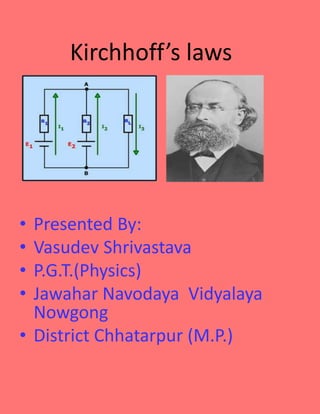
- 1. Kirchhoff’s laws • Presented By: • Vasudev Shrivastava • P.G.T.(Physics) • Jawahar Navodaya Vidyalaya Nowgong • District Chhatarpur (M.P.)
- 2. Kirchhoff’s lawsare fundamental to circuit theory. They quantify how current flows through a circuit and how voltage varies around a loop in a circuit. Kirchhoff’s circuit laws were first described in 1845 by the German physicist Gustav Kirchhoff. Kirchhoff’s Junction Rule Kirchhoff’s First Law According to Kirchhoff’s Current Law, The total current entering a junction or a node is equal to the charge leaving the node as no charge is lost. Put differently, the algebraic sum of every current entering and leaving the node has to be null. This property of Kirchhoff law is commonly called as Conservation of charge wherein, I(exit) + I(enter) = 0 In the above figure, the currents I1, I2 and I3 entering the node is considered positive, likewise, the currents I4 and I5 exiting the nodes is considered negative in values. This can be expressed in the form of an equation: I1 + I2 + I3 – I4 – I5 = 0 The term Node refers to a junction or a connection of two or more current-carrying routes like cables and other components. Kirchhoff’s current law can also be applied to analyze parallel circuits.
- 3. Kirchhoff’s first law are also known by several names as Kirchhoff’s Current Law (KCL), Kirchhoff’s Junction Rule, Kirchhoff’s point rule, Kirchhoff’s nodal rule. It is an application of the principle of conservation of electric charge. The law states that at any circuit junction, the sum of the currents flowing into and out of that junction are equal. In simple terms, what KCL really says is that, The sum of all currents entering a node is equal to the sum of all currents leaving the node. We perform analysis on all nodes based on the inflow and outflow of current. Current directions at the node are based on presumed directions of the currents. As long as the assumed directions of the currents are consistent from node to node, the final result of the analysis will reflect the actual current directions in the circuit. Mathematically, Kirchhoff’s Current law is stated as follows where n is the total number of branches carrying current towards or away from the node. Solving Circuits Using KCL Let us look at a few examples that demonstrate the law in practice and understand its importance in determining the unknown parameters. Example 1: Let us consider a network of assumed directions of the current as shown below. Let us choose a sign convention such that currents entering the node are positive, and the currents leaving the node are negative. With this convention, KCL applied at the node yields the equation: i1(t)+i2(t)−i3(t)=0
- 4. or, i1(t)+i2(t)=i3(t) This amounts to the statement that the total current entering the node is the same as the total current leaving the node. Example 2: Using KCL to determine the value of the unknown current i in the circuit below. Assuming that the current entering the node is positive, the sum of the currents is given by the equation, 4A−(−1A)−2A−i=0 ⇒4A+1A−2A=3A Therefore, i = 3A, leaving the node(since our assumed direction of i on the diagram is that it is leaving the node, and our numerical value for i is positive). Disadvantages of KCL KCL is valid only if the total electric charge is constant in the circuit. KCL is suitable for high-frequency AC circuits. Practice Questions 1. Calculate currents I_(1)and I_(2) in the given circuit?
- 5. Solution: Let us identify the different nodes in the circuit as A and B. If the current entering the nodes are assumed positive, then 2 A – I1 = 0. Therefore, I1 = 2 A. Applying KCL at node B, we get the equation I1 + I2 = 0. Since we know the value of I1, we can easily determine the value of I2 as –2 A. 2. Calculate the currents I1 and I2, in the circuit below. Solution:
- 6. Let us identify the two nodes in the circuit as A and B. Now applying KCL to node A, assuming the currents leaving the nodes as positive, we get Now applying KCL to node B, we get Substituting the value of I1 in the above equation, we get Solving, we get
- 7. Kirchhoff’s Second Law According to Kirchhoff’s Voltage Law, The voltage around a loop equals to the sum of every voltage drop in the same loop for any closed network and also equals to zero. Put differently, the algebraic sum of every voltage in the loop has to be equal to zero and this property of Kirchhoff’s law is called as conservation of energy. When you begin at any point of the loop and continue in the same direction, note the voltage drops in all the direction either negative or positive and return to the same point. It is essential to maintain the direction either counterclockwise or clockwise; else the final voltage value will not be equal to zero. The voltage law can also be applied in analyzing circuits in series. When either AC circuits or DC circuits are analysed based on Kirchhoff’s circuit laws, you need to be clear with all the terminologies and definitions that describe the circuit components like paths, nodes, meshes, and loops. Kirchhoff’s second law, also known as Kirchhoff’s voltage law (KVL) states that the sum of all voltages around a closed loop in any circuit must be equal to zero. This again is a consequence of charge conservation and also conservation of energy. Kirchhoff’s Voltage Law Kirchhoff’s Second Law or the voltage law states that The net electromotive force around a closed circuit loop is equal to the sum of potential drops around the loop It is termed as Kirchhoff’s Loop Rule, which is an outcome of an electrostatic field which is conservative. Hence,
- 8. If a charge moves around a closed loop in a circuit, it must gain as much energy as it loses. The above can be summarized as ” the gain in energy by the charge = corresponding losses in energy through resistances Mathematically, the total voltage in a closed loop of a circuit is expressed as ∑V=0. The below figure illustrates that the total voltage around a closed loop must be zero. This law manages the voltage drops at different branches in an electrical circuit. Consider one point on a closed loop in an electrical circuit. If somebody goes to another point in a similar ring, then he or she will find that the potential at that second aspect might be not quite the same as the first point. On the off chance that he or she keeps on setting off to some unique point on the loop and he or she may locate some extraordinary potential in that new area. If he or she goes on further along that closed loop, eventually he or she achieves the underlying point from where the voyage was begun. That implies, he or she returns to a similar potential point in the wake of the intersection through various voltage levels. It can be then again said that the gain in electrical energy by the charge is equal to corresponding losses in energy through resistances.
- 9. Solving circuit using Kirchhoff’s Second Law o The first and foremost step is to draw a closed loop to a circuit. Once done with it draw the direction of the flow of current. o Defining our sign convention is very important o Using Kirchhoff’s first law, at B and A we get, I1+I2=I3 o By making use of above convention and Kirchhoff’s Second Law From Loop 1 we have: 10=R1∗I1+R3∗I3 =10I1+40I3 1=I1+4I3 From Loop 2 we have : 20=R2∗I2+R3∗I3
- 10. 20I2+40I3 1=I2+2I3 From Loop 3 we have : 10−20=10I1−20I2 1=−I1+2I2 By making use of Kirchhoff’s First law I1+I2=I3 Equation reduces as follows (from Loop 1 ) : 1=5I1+4I2 Equation reduces as follows ( from Loop 2 ) : 1=2I1+3I2 This results in the following Equation: I1=−13I2 From last three equations we get, 1=13I2+2I2 I2=0.429A I1=0.143AI3=0.286A Kirchhoff’s Law Solved Example 02 If R1 = 2Ω, R2 = 4Ω, R3 = 6Ω, determine the electric current that flows in the circuit below. Solution: 1. Following are the things that you should keep in mind while approaching the problem:
- 11. You need to choose the direction of the current. In this problem, let us choose the clockwise direction. When the current flows across the resistor, there is a potential decrease. Hence, V = IR is signed negative. If the current moves from low to high then the source of emf (E) signed positive because of the charging of energy at the emf source. Likewise, if the current moves from high to low voltage (+ to -) then the source of emf (E) signed negative because of the emptying of energy at the emf source. In this solution, the direction of the current is the same as the direction of clockwise rotation. – IR1 + E1 – IR2 – IR3 – E2 = 0 Substituting the values in the equation, we get –2I + 10 – 4I – 6I – 5 = 0 -12I + 5 = 0 I = -5/- 12 I = 0.416 AThe electric current that flows in the circuit is 0.416 A. The electric current is signed positive which means that the direction of the electric current is the same as the direction of clockwise rotation. If the electric current is negative then the direction of the current would be in anti-clockwise direction. Ncert Problem A battery of 10 V and negligible internal resistance isconnected across the diagonally opposite corners of a cubical networkconsisting of 12 resistors each of resistance 1 Ω (Fig. 3.23). Determinethe equivalent resistance of the network and the current along eachedge of the cube.
- 12. Example 3.7 Determine the current in each branch of the net work shown in Fig. 3.24.
- 15. Example 3.8 The four arms of a Wheatstone bridge (Fig. 3.26) have the following resistances: AB = 100Ω, BC = 10Ω, CD = 5Ω, and DA =60Ω. ]
- 17. Determine the current in each branch of the network shown inFig. 3.30: Advantages and Limitations of Kirchhoff’s Law The advantages of the laws are: It makes the calculation of unknown voltages and currents easy The analysis and simplification of complex closed-loop circuits becomes manageable