SlideShare ist ein Scribd-Unternehmen logo
1 von 64
Downloaden Sie, um offline zu lesen
Water from Roads
      A handbook for technicians and farmers
                          on
           harvesting rainwater from roads


During rainy days, the road from Kitui to       The result of the dual function is
that gullies
Kibwezi functions both as a river and a road.   damage both the road and
adjacent farmland.


Rainwater run-off from the Nairobi-Mombasa highway is diverted into an earth
dam at Salama, which provides water for livestock, brick-making and forestry
without any erosion.
.

                    Erik Nissen-Petersen
                             for
    Danish International Development Assistance (Danida)


                                      1
2006
                 Technical handbooks in this series :
Titles                                   Contents
1 Water for rural communities            Lessons learnt from Kitui pilot projects
2 Water supply by rural builders         Procedures for being rural contractors
3 Water surveys and designs              Survey, design and cost of water projects
4 Water from rock outcrops               Rock catchment tanks, masonry and earth
dams
5 Water from dry riverbeds               Wells, subsurface dams, weirs and sand
dams
6 Water from roads                       Rainwater harvesting from roads
7 Water from small dams                  Ponds and small earth dams built
manually
8 Water from roofs                       Various types of roof catchments for
domestic use

These handbooks can be obtained free of charge by either collecting them from the
office of ASAL Consultants Ltd., or by paying through bank transfer the cost of
sending the manuals by courier. For further details, please contact:
asal@wananchi.com with copy to asalconsultants@yahoo.com

Published by
ASAL Consultants Ltd. for
the Danish International Development Assistance (Danida) in Kenya
Text, sketches and photos by
Erik Nissen-Petersen
Computer drawings by
Catherine W. Wanjihia

Editing and proofs by
Prof. Elijah K. Biamah, Amin Verjee and Steen S. Larsen
Printer
Printwell Ind. Ltd., P.O. Box 5216-0506, Nairobi, Kenya

Website by
Edwin Ondako
Distribution by
ASAL Consultants Ltd. P.O. Box 739, Sarit 00606, Nairobi, Kenya
asal@wananchi.com       asalconsultants@yahoo.com
Fax/Tel : 254 020 2710296 and 4766144 Mobiles: 0733 619 066 and 0722 599
165
Website : www.waterforaridland.com


 Copyright.
The copyright of this handbook is the property of the Royal Danish Embassy
in Kenya. Downloading from the internet and photocopying of the handbooks
is permitted provided the source is acknowledged.


                                        2
Contents                                                                      Page
Acknowledgement …………………………………………………………                                          iv
Foreword …………………………………………………………………..                                            v
Technical vocabulary ……………………………………………………..                                     vi
Measurements and conversions ………………………………………….                                  vii

Chapter 1.    Damage by road run-off water ………..…………….. 1
1.1   Road damage by run-off ……….………………………………….                                  1
1.2   Loss of people and livestock ………………………………………                               2
1.3   Gullies made by culverts ……………………………………….….                                3
1.4   Volume of rainwater running off roads ……………………………                          4
1.5   Benefits from rainwater running off roads …………………………                       5

Chapter 2.    Earth dams ………………………………………………                                      6
2.1   Murram pits ………………………………………………………..                                        6
2.2   Small pans ………………………………………………………….                                         8
2.3   Large pans ………………………………………………………….                                         8
2.4   Ponds ……………………………………………………………….                                            9
2.5   Charco dams ……………………………………………………….                                         9
2.6   Hillside dams ………………………………………………………                                       10
2.7   Valley dams ………………………………………………………..                                       11
2.8   Tools and equipment for soil works ……………………………….                          12
2.9   Analysis of soil samples ……………………………………………                                13
2.10  Construction costs of earth dams …………………………………..                          14
2.11  References on earth dams ………………………………………….                                14
Chapter 3.    Water tanks ………………………………………………                                    15
3.1   Advantages of water tanks ………………………………………….                               15
3.2   Excavation of hemispherical tanks ……………………………….                           15
3.3   Hemispherical tank built of burnt bricks …………………………..                     16
3.4   Hemispherical tank built of ant-hill soil, lime, sand and cement ....     19
3.5   Hemispherical tank built of ferro-cement …………………………                       23
3.6   Cylindrical underground water tanks …….………………………..                        26
3.7   Berkads ……………………………………………………………..                                         28
3.8   Rectangular water tanks ……….……………………………………                                33
3.9   References on water tanks ………………………………………….                               33
Chapter 4. Subsurface dams ……………………………………………...                                 34
4.1   Water in sand reservoirs …………………………………………….                               34
4.2   Floodwater passing roads …………………………………………..                               34
4.3   Hand-dug wells …………………………………………………….                                      35
4.4   Subsurface dams. weirs and sand dams …………………………….                         36
4.5   Subsurface dams built of soil ………………………………………                             37
4.6   Weirs ……………………………….………………………………                                           39
4.7   Sand dams ……………………………….…………………………                                         40
4.8   Sand harvesting ……………………………………………………                                      44
4.9   Gold and gem stones from sand dams …………………………….                           45
4.10  References on subsurface dams, weirs and sand dams ……………                  45

Chapter 5.      Run-off farming …………………………………….…                                46
5.1   Drainage from roads by engineers …………………………………                            46
5.2   Drainage from roads by farmers …………………………………..                            47
5.3   Soil bunds ………………………………………………………….                                        50
5.4   Gullies ……………………………………………………………..                                         51
5.5     Macro-irrigation …………………………..……………………….                                 55
5.6     References on run-off farming …………………………………….                           57


                                             2
Acknowledgments
Much gratitude is due to Birgit Madsen of the Royal Danish Embassy in Nairobi for
having taken a leading role in documenting the experiences of various techniques of
creating low-cost water supply structures in the semi-desert, arid and semi-arid
regions of the world.

Many thanks are also due to Prof. Elijah Biamah, Steen Larsen and Amin Verjee, who
assisted with proof-reading the text and editing, to Edwin Ondako who created the
website and loaded this handbook and others onto it, and to Oliver D’Cunha, who
managed the printing at Printwell Ind.Ltd..

Thanks are also due to the many engineers, technicians, artisans and self help groups
who participated in several training courses and other assignments on small earth
dams implemented by ASAL Consultants Ltd. for Danida, SIDA, UNDP, the EU and
other organisations in a dozen countries over the last three decades.

This handbook, Water from Roads, is one of a series of 8 publications on Water in
Arid Lands, financed by the Danish International Development Assistance (Danida).

To promote the simple technologies described in the handbooks, these can be read or
downloaded free of charge from our website www.waterforaridland.com .

Erik Nissen-Petersen
Managing Director
ASAL Consultants Ltd.
P.O. Box 739, 00606, Nairobi, Kenya
Tel/fax: +254 (0)20 2710296
Mobile: +254 (0)733 619066 / +254 (0)722 599144


Disclaimer
The designs and construction procedures described in this handbook are based on the
author’s experiences and observations over 30 years. The tanks and earth dams
described herein, when properly constructed and maintained, have performed
exceptionally well. However, local climatic, geological, seismic and soil conditions
vary widely, as does the quality of materials and workmanship, and while the author
and Danida are keen to encourage the replication of the ponds and dams described in
this handbook, they cannot accept liability for the failure of a water harvesting system
based on the designs and construction procedures described herein.


                                           3
Foreword

This handbook on water from roads produced by Danida in Kenya is targeted at all
organizations involved in road construction works and especially the Ministry of
Roads and Public Works.

Currently, all road construction works have no provision for the storage of run-off
water generated from road drainage. This handbook then comes when road engineers
have been trained and sensitized on the importance of safe disposal of run-off water
from roads.

Water from Roads as a handbook is expected to serve as a guide for road engineers
and contractors who are involved in the design and construction of road drainage
works. The handbook provides valuable technological advice for harnessing road run-
off water.

This handbook provides all the technical information required for the design and
construction of all the types of earth dams, water tanks and subsurface dams. Also the
handbook contains information on run-off farming.

It is this understanding of the technical information contained herein that our roads
could be designed better by providing viable alternative technologies options for
harnessing road drainage. This handbook also provides alternative technologies for
run-off water utilization.


Mrs Elizabeth Mibey
Principal Environmental Impact Assessment (EIA) Officer
Ministry of Roads and Public Works


                                          4
TECHNICAL TERMS AND ABBREVIATIONS
ASAL                  =    Arid and Semi-Arid Lands
ASALCON               =    ASAL Consultants Ltd.
Batter                =    Gradient of a dam wall
Bench mark (BM)       =    A fixed point for measurements
Berm                  =    Area between a reservoir borrow pit and dam wall
Base                  =    Foundation for a dam wall
Borrow pit            =    An excavation from where soil is taken
Bill of Quantities (BQ)=   List of materials and labour, with costing
Catchment             =    Area draining run-off water to a common point
Centre line           =    An imaginary line through the centre of a crest at
                           the upper level of the freeboard
Contour line           =   Horizontal line connecting points of equal altitude
Crawler                =   Bulldozer
Crest                  =   Top of dam wall
Danida                 =   Danish International Development Assistance
Diaphragm              =   Blanket of soil on upstream side of embankment
Downstream batter      =   Downstream slope of a dam wall
Downstream toe         =   Downstream edge of a dam wall
Draw-off pipe          =   Pipe draining water by gravity
Embankment             =   Dam wall
Evaporation            =   Water lost as vapour from a water surface
EU                     =   European Union
Freeboard              =   Safety height of dam wall from maximum water level
Gradient               =   Slope
Hafir (Arabic term)    =   A type of earth dam for livestock and people
Inselberg              =   A massive bare rock outcrop common in the tropics
Impervious             =   Not letting water through
Key (Cut-off trench)   =   Trench of clayey soil to prevent seepage
Live fencing           =   Fence of vegetation, preferably thorny
Murram                 =   A clayey soil packed with stones found in laterite soil
NIL                    =   Cement slurry
Seepage                =   Water seeping through soil
Sediment               =   Soil deposited in reservoir
Settlement             =   Soil compacting and shrinking due to weight
SIDA                   =   Swedish International Development Assistance
Sill                   =   Low concrete wall across spillway
Siltation              =   Dam reservoirs being filled with silt
Siphon                 =   Pipe lifting water over a high point to a lower level
SODIS                  =   SOlar DISinfection (of water)
Spillway               =   Overflow channel discharging excess floodwater
Storage ratio          =   Volume of water in relation to volume of soil
Turbid                 =   Muddy, unclear water carrying sediment
Throw-back             =   Length of a reservoir full of water
Topographical          =   Relating to the shape and height of the land
UNDP                   =   United Nations Development Programme
Upstream batter        =   Upstream slope of a dam wall
Upstream toe           =   Upstream edge of a dam wall
Valley dam             =   Dam constructed in a valley with a straight embankment
Washout                =   Section of a dam wall washed away by water


                                       5
ILLUSTRATION OF TECHNICAL TERMS


Cut-through section of a three-dimensional sketch of a dam wall.


MEASUREMENTS AND CONVERSIONS
Length        1 metre = 3.28 feet
              1 km = 0.62 miles

Area          1 acre = 4,047 m2               = 0.4047 hectares (ha)
              1 ha = 10,000 m2                = 2.471 acres
              1km2 = 100 ha                   = 247.1 acres

Volume        1 litre = 1.75 pints            = 0.22 Imp gallons (or 0.26 US galls)
              1 m3 = 1,000 litres (l)         = 220 Imp gallons (or 260 US gallons)
              1 Imperial gallon               = 4.550 l
              1 US gallon                     = 3.785 l

Weight        1 tonne                         = 1,000 kg
              1 British ton                   = 1,016 kg
              1 US ton                        = 907 kg

Volumes and weight of materials
            1 m3 water                        = 1,000 kg
            1 m3 dry soil                     = 1,230 to 2,000 kg
            1 m3 compacted soil               = 2,180 kg, approximately
            1 m3 loose gravel                 = 1,745 kg, approximately
            1 m3 stones                       = 2,400 kg to 2,900 kg

Exchange Rate Used in the Manual
            Ksh           = Kenya Shillings
            Ksh 72/       = USD 1.00 (October 2006)


                                          6
Chapter 1.            Damage by road run-off water
1.1    Road damage by run-off
Rainy seasons are blessings for farmers
but hard times for motorists. Streets get
flooded and impassable in towns due to
blocked or under-dimensioned sewage
systems. In the countryside, villagers may
be cut off from the rest of the world due to
deep holes filled with water and mud,
which vehicles cannot drive through. The
photo shows the depth of such a hole in a
road after the water has evaporated.


Here the rainwater has cut a small gully on
one side of the road. Since usually no
repairs take place during rainy seasons,
every additional rain shower will make the
gully deeper.


The following rain showers have now
deepened and widened the small gully into
a deep cut that runs halfway across the
road and through the farmland until the
flood reaches a riverbed.

The rainwater continues to remove
considerable amounts of murram from the
road and soil from the farmland, which is
eventually transported to the sea via
riverbeds, where it chokes fish, coral reefs
and damages the marine ecology.

A few more rain showers have now
extended the gully right across the road
and made it impassable.

The only way of by-passing the gully is to
drive over the farmer’s land on the higher
side of the road, where vehicles have cut a
deep track. No crops will ever grow there
again.


                                           7
A road-grader has made a cut-off channel to
divert run-off water from a road to a field.

While this preserves the road, it damages
the field, because the run-off water will
create a gully stretching all the way from
the road to the nearest riverbed.


After a few years, the run-off water from
the road will have deepened and widened a
small gully in a fertile farmland to a bare
valley where all the top soil has been
eroded. Only hardy thorny scrubs can grow
there.

Where no preventive action is taken, a
small gully may turn into a desolate moon
landscape as seen in the photo.

In this way, thousands of acres of fertile
farmland are being washed away every year
by uncontrolled rainwater running off
roads.

Another hazard created by rainwater
running off roads is that some people and
animals lose their lives, while trying to
cross a road over a riverbed flooded by
rainwater.


1.2    Loss of people and livestock
Often rainwater comes as a flash flood
several metres high, which carries uprooted
trees and drowned animals – and sometimes
drowned people - into the brown maelstrom
of flooded riverbeds. The photo shows the
damage by erosion to a low bridge after a
flood has passed over it.

This handbook explains in simple terms,
how other people have stopped the erosion
process and improved their living standards.


                                          8
1.3    Gullies made by culverts
Culverts are concrete rings laid as
drainage pipes under roads at their lowest
points. The culverts drain run-off water
from the upper side of a road to a riverbed
on the lower side of the road.

The photo shows a series of concrete
check dams along the newly built Nairobi-
Mombasa highway. The check dams
reduce the velocity of water before it
enters the culvert seen in the left lower
corner.


On the other side of the road, the culvert
discharges the water into a small ditch
which spills the water onto grazing land
without any soil protection. This ditch
will turn into a deep gully after some
rainy seasons and the topsoil and grass
will be washed away. In the near future,
the Maasai will have to graze their
livestock elsewhere.


This photo, of the same road near Sultan
Hamud, gives a good impression of the
huge volumes of run-off water from roads
after a small rain shower.

Luckily, this water is discharged into a
riverbed without any erosion.


This photo shows a culvert near Arusha
that discharges run-off water into a ditch
that will either turn into a gully or a
riverbed after a few more rainy seasons.


                                             9
1.4    Volume of rainwater running off roads
The volume of rainwater running off from a 1 km long murram or tarmac road from a
rain shower of 30 mm, can be estimated as follows:

Road area:            1,000 m long and 4 m wide
Road surface:         Murram or soil
Run-off efficiency:   80%
Rainfall:             30 millimetres

1,000 m x 4 m x 80 x 30 mm = 96,000 litres = 96 cubic metres from 1 km road
              100

Bearing in mind that the average annual rainfall in a season is about 600 mm in most
ASAL regions, the total annual volume of run-off water from a 1 km long murram
road is:

        1,000 m x 4 m x 80 x 600 mm = 1,920,000 litres = 1,920 cubic metres
                      100

Considering that one local Zebu cow consumes about 20 litres of water in a day, then
185 local cows can be watered every day in a year (1,920,000 litres minus 30% loss
(576, 000 litres) = 1,344,000 litres / 20 litres / 364 days = 185) from only 1 km of
murram road.

This example shows clearly that roads can supply huge volumes of water for
livestock, irrigation, forestry, construction works, etc., provided the harvested water
can be stored until it can be used in the following dry season.

If the stored water is intended for domestic use, it can be treated using grounded seed
from Moringa stenopetala to settle the dirt in the bottom of a container. Thereafter the
water should be sterilised either by boiling or by the Sun’s ultraviolet rays that can
destroy all bacteria in water filled in transparent bottles and exposed to 6 hours
sunshine.


Run-off water from the Kanziku road in Kitui has been harvested into this pond,
which was made by scooping out a depression and placing the soil as a dam wall on
the lower side of the excavation. Hopefully, the woman will treat the water she is
drawing, before it will be used for domestic purposes.


                                          10
1.5      Benefits from rainwater running off roads
As shown on the previous page, the 1,344 cu.m. run-off water from 1 km of road can
water 185 local cows every day in a year, while taking into account that 30% of the
water may be lost due to evaporation or seepage. Besides watering livestock, the
water could also be used for other purposes, such as:

      1. Tree nurseries, woodlots, orchards and vegetative fencing of fields and
         homesteads, which provide income from sale of tree seedlings, timber,
         firewood, fruits, etc.

      2. Manufacturing of burnt bricks, concrete blocks, culverts and other building
         materials that can be sold.

      3. Sale of water to neighbours for watering their livestock, construction works,
         etc.

      4. Raising ducks, geese, fish and bees in or near open water reservoirs.

      5. Sale of sand harvested from weirs and sand dams in gullies and riverbeds.

      6. Recharge of hand-dug wells near subsurface dams, weirs and sand dams in
         riverbeds from where domestic water can be drawn.

      7. Using run-off water from tarmac roads for domestic use is not advisable due to
         the risk of contamination by tar, oil, rubber, etc.

      8. Increased agricultural production from fields irrigated by road run-off water.


       Two examples of school boys earning cash for their schooling:


       Harvesting sand for sale from a sand dam Assisting water vendors in bringing
       built in a gully near Lake Victoria. The  empty jerrycans to a water point near
       construction cost of 10 sand dams was     Voi.
       recovered from sale of sand in 1 ½ years.

The next chapters will describe four types of rainwater harvesting from roads, namely
earth dams, tanks, subsurface dams and run-off farming, which farmers can construct
themselves for a minimum of investment.


                                            11
Chapter 2.            Earth dams
The most common technique for harvesting run-off water from roads is to store the
harvested water in reservoirs built of soil. The construction cost consists only of
labour to excavate and transport soil. There is no need to purchase cement or
reinforcement iron from hardware shops.

Several types of soil structures that can be constructed successfully by farmers are
described in the following chapters.

2.1    Murram pits
Murram pits, also called borrow pits, are always situated along roads and are easy to
convert into water reservoirs, because only excavation of one or two trenches is
required. However, before digging the trenches, it is advisable to discuss the issue
with the local authorities.

Murram pits are found along most roads,
because the material (murram) excavated
from them is used for building the roads.
Whenever a road is re-carpeted with murram,
the existing pits are either widened, or new
murram pits are excavated.

In any case, the floor of murram pits is
usually either impermeable laterite or rock,
through which there is hardly any seepage. If
the walls or the floor of a murram pit are
stony they may allow some seepage but that        A murram pit along a road in Kitui
can be sealed by plastering a mixture of clayey
soil and lime onto the leaking parts.

The run-off water from a road is diverted into a murram pit by excavating a trench
reaching upwards from the murram pit to the ditch running along the road. To prevent
sedimentation of the water reservoir in the murram pit, the trench should have a
gradient of about 3 cm for every 100 cm.

A gradient of 3:100 can be measured
by levelling a spirit level on a 300 cm
long timber having a leg being 9 cm
long.


This photo shows a cut-off trench that has
been cut by a road grader for the purpose of
diverting run-off water from the road into
an adjacent field. Similar trenches can be
excavated by hand, or ox-scoops, to divert
rainwater into murram pits.


                                          12
When a murram pit has been filled with rainwater running off a road, the surplus
water must be discharged over a spillway to avoid damage to the water reservoir. The
height of spillways is important. If a spillway is too low, the maximum storage
capacity of the water reservoir is wasted. If a spillway is too high, the lowest part of
the wall will not be able to withstand the water pressure and it will be washed away
thereby destroying the water reservoir.

Preferably, the surplus water from a filled
up murram pit should pass over a spillway
that diverts the water back to its original
course of discharge.

In practice, the optimal height of spillways
and the discharge of surplus water from
murram pits can be found by heighten the
spillway in stages.

Spillways should always be protected by            The side of a spillway protected by stones
large stones packed with smaller stones
into the floor and sides of the spillway to
prevent erosion and ensure that the final
height of a spillway is maintained.

Water can be drawn from murram pits in
many ways depending on the usage of the
water.


                                                      A girl filling jerrycans with water
                                                      from a murram pit for domestic use.


Two boys pumping water from a murram pit for
irrigation of vegetables using a Money-maker foot
pump costing about Ksh 5,000.


                                              13
2.2 Small pans
Pans are natural depressions without any dam walls around their water reservoirs.
Pans were scooped out by elephants long time ago whereas murram pits are man
made. Local people call these pans silanga ya ndovu, meaning elephant dams.

Rainwater running off roads can be diverted into pans by excavated trenches, or along
stone bunds, having a gradient of about 3:100 as described above.


A small depression next to a road at
Mbuinzau at Kibwezi has been converted
into a pan by building a “speed bump”
across the road, which diverts run-off water
into the pan.

Please note that the downstream side of the
pan has been eroded by surplus water due to
lack of a spillway covered with stones.

                                               A small pan next to a road at Kibwezi.

2.3 Large pans
Large pans for storage of run-off water
from roads and the annual floods from
Angola, are common water sources in the
extremely flat land of Ovamboland in
Northern Namibia. The pans are used for
raising fish, watering livestock and
domestic uses as well.
Deep pans in the Sudan are called hafirs.      An excavated pan in northern Namibia
                                               that harvests run-off water from roads.

An old pan being desilted
manually in Taveta, for
Food-for-Work, apparently
without a proper workplan.


A pan built recently
by crawlers in the flat
land of Taveta financed
by TTAP/Danida.


                                         14
2.4    Ponds
Ponds are small earth dams that are made by scooping out soil and using the soil to
construct a dam wall on the lower side of the water reservoir. There are three main
types of small earth dams namely: Charco dams, hillside dams and valley dams.
These dams are described in detail in another handbook of this series, namely Water
from Small Dams, and will therefore only be described briefly in this handbook.

2.5 Charco dams
Charco dams are suitable where run-off from roads spill over onto flat land,
preferably with silty or clayey soils. The best design for charco dams resembles a
calabash cut in half for scooping and pouring water as shown in the photo below.


                                                      A calabash cut in half.


Plan and profiles of a charco dam                    A charco dam in Tanzania.

Charco dams and other small dams can be constructed in stages during dry seasons,
when manual labour is available. Alternatively, neighbours who want to draw water
from somebody else’s dam can be requested to scoop out and transport one
wheelbarrow of soil for every jerrycan of water they want to carry home, or the water
can be sold for cash and used to hire contract labourers for deepening a dam.

At every stage, the water reservoir can be made deeper and the dam wall higher from
soil excavated from the reservoir. This process can be continued until the dam can
hold enough water throughout the year.


Cross sections of a charco dam showing the first and last stage of excavation works.


                                         15
2.6    Hillside dams
Hillside dams are suitable where run-off water from roads can be diverted onto
sloping land or hillsides. These dams have an oval-shaped water reservoir with a
semi-circular dam wall on the lower side of the reservoir.


                                                       A hillside dam at Lukenya along
                                                       the Nairobi - Mombasa highway.


Plan and profiles of a hillside dam.


                                                       Another hillside dam at Salama
                                                       on the same highway.

Hillside dams must have a spillway at each
end of the curved dam wall in order to
discharge surplus water when the reservoir
is full.

The two spillways should be at the same
horizontal level in order to discharge surplus
water safely. A horizontal line can be sighted
along the two water levels in a circular transparent
hosepipe filled halfway with water.

Spillways must be reinforced with large stones
interplanted with grass at the dam wall to prevent Sighting along the two water levels in a
erosion by over-flowing water.                     circular transparent hosepipe filled
                                                   halfway with water, gives an exact
Also the floors of spillways should be covered      horizontal line.
with stones and grass and interplanted with types
of grass having many runners and long roots.


                                           16
2.7 Valley dams
Valley dams are suitable where run-off water from roads is discharged into valleys.
Valley dams have straight embankments (dam walls) with a wide spillway at each
end of the embankment. Although valley dams require less excavation work than
charco and hillside dams, they are vulnerable and could be washed away by
unexpectly large volumes of run-off water. Considering the unpredictable weather
pattern created by global warming, many valley dams have been destroyed by
extremely high rainfall.


Plan and profiles of a valley dam. Source: Water from ponds, pans and dams by the
author for RELMA/Sida in Kenya, 2005.


        Construction of the designed dam by manual labour.


                                        17
2.8    Tools and equipment for soil works


Plots having a volume of      The “owners” of the plots excavate the soil and load it
1 cubic metre of soil are     onto wheelbarrows. Women transport the soil to the dam
pegged out and distributed.   wall, off-load it and compact it manually.


       Various sizes of plots all with the same volume of 1 cubic metre of soil.


An ox-scoop made of 4 mm steel plate; with a plough and ox-scoop, two men and two
oxen can excavate and transport more soil than 10 able-bodied men.


                                          18
2.9    Analysis of soil samples
It is important to analyse samples of soil that shall be used for construction of dams in
order to minimise seepage losses. Naturally, the most clayey soil found on a dam site
should be used for those parts of a dam wall that should be as impermeable as
possible. Sandy soils should be used on the downstream side of a dam wall where
weight, and not impermeability, is required.

A soil test that gives the percentage of clay, silt, sand and gravel can be carried out


using a transparent bottle as follows:
Fill a transparent bottle 1/3 with a soil sample and 1/3 with water. Add a pinch of salt.
Shake the bottle vigorously for 1 minute. Leave it for 1 hour, then shake again. After
4 hours, measure the thickness of each layer in the bottle. The upper layer is clay
followed by silt, sand and gravel at the bottom. Find the percentage of each layer by
measuring its thickness against the total thickness of the soil sample and multiply by
100.

Another simpler but less accurate method is to remove the caps and bottoms of some
transparent plastic bottles. Fill the bottles halfway with soil and top up with water.
Keep on adding water while watching the speed with which the water infiltrates the
soil.


Soil with the least infiltration has the highest clay content and is therefore the most
suitable soil to use for the impermeable parts of a dam wall and its reservoir.
Source: Water from ponds, pans and dams by the author,for RELMA/Sida in Kenya, 2005.


                                           19
2.10 Construction costs of earth dams
The four types of earth dams listed below have different construction costs depending
on the construction method and the water-to-soil ratio.

a) The construction method relates to whether the excavation is done:
   1) Manually with shovels and wheelbarrows costing about Ksh 100/cu.m. soil.
   2) With draught animals, scoops, ploughs and carts, costing about Ksh 60/cu.m.
   3) Hiring a farm tractor with a plough and scoop costing about Ksh 80/cu.m.
   4) Hiring a crawler (bulldozer) costing about Ksh 300/cu.m. soil.

b) The water-to-soil ratio depends on the type of dam, because the volume of water:
   1) A pond is equal to the volume of excavated soil, therefore the ratio is 1:1.
   2) A charco dam is equal to the volume of soil, therefore also 1:1.
   3) A hillside dam is 1.5 times more than the excavated soil, therefore 1.5:1.
   4) A valley dam is 3 times more than the excavated soil, therefore 3:1.

Although valley dams have the lowest construction cost per m3 soil, because they can
store about 3 times more water than the excavated soil, they have a much higher rate
of failure than other types of earth dams.

 Type       of   Construction   Reservoir    Water         Excava-     Cost     Total      Cost per
 dam             method         volume       to soil       ted soil    per      cost       cu.m. of
                                cu.m.        ratio          cu.m.      cu.m.    Ksh.       water
                                                                                           storage
                                                                                           Ksh.
 Excava-
 ted pond        Manual               100            1:1   100     x      100   = 10,000       100

 Charco          Manual               500            1:1   500     x      100   = 50,000       100
 dams
                 Tractor              500            1:1   500     x       80   = 40,000        80
                 Oxen                 500            1:1   500     x       60   = 30,000        60

 Hillside        Manual               500        1.5:1     333     x      100   = 33,300        66
 dams            Tractor              500        1.5:1     333     x       80   = 26,640        53
                 Oxen                 500        1.5:1     333     x       60   = 19,980        40

 Valley          Crawler             5,000           3:1   1,670   x      300   =501,000       100
 dams            Manual              5,000           3:1   1,670   x      100   =167,000        33
                 Tractor             5,000           3:1   1,670   x       80   =133,600        27
                 Oxen                5,000           3:1   1,670   x       60   =100,200        20
Source: Water from ponds, pans and dams by the author, for RELMA/Sida in Kenya, 2005.

2.11 References on earth dams
Design and Construction of Small Earth Dams. Nelson, K.D. Australia 1985.
Field Engineering for Agricultural Development. Hudson, Oxford, UK.
Small Earth Dam built by Animal Traction. Nissen-Petersen, E., Danida Kenya 1990.
Small earth dams. Brown, L.N. University of California, USA 1965.
Water from ponds, pans and dams. Nissen-Petersen, E. RELMA/Sida Kenya 2005.
Water from Small Dams. Nissen-Petersen, E. Danida Kenya 2006.


                                                20
Chapter 3.               Water tanks

3.1 Advantages of water tanks.
In regions with sandy soils, much water is usually lost from seepage in earth dams,
and additional water is also lost by evaporation due to the large surface area of the
water reservoirs. Furthermore, earth dams have other disadvantages such as siltation
of reservoirs due to lack of proper soil conservation, erosion by livestock watered in
the reservoirs, water-borne diseases and vector carried diseases.

Since it is difficult and expensive to reduce these disadvantages of earth dams, it may
be more applicable to build water tanks. Although the capacity of water tanks is
smaller than earth dams, they have several advantages, such as:

      1) Seepage can be eliminated by lining water tanks with clay, anthill soil, burnt
         bricks, concrete blocks, ferro-cement or butyl rubber sheets.

      2) Evaporation can be greatly reduced by roofing water tanks with live
         vegetation on wires, iron sheets, concrete covers or ferro-cement domes.

      3) Siltation can be eliminated by excavating and regularly emptying silt traps.

      4) Contamination by livestock and vectors can be avoided if the tanks are
         covered.

A number of well-functioning water tanks for harvesting rainwater run-off from roads
are described in the following pages. A common feature for all the tanks is that none
of them have a square or rectangular shape because these shapes always tend to crack.

Water tanks should always have a hemispherical or a cylindrical shape, because these
shapes distribute equally the external and internal pressures on the wall, thereby
eliminating the risk of cracks due to uneven tension.

3.2    Excavation of hemispherical tanks. Another common feature is that
the tanks are built against the wall of solid soil exposed by the excavation works
thereby ensuring a solid support of the entire tank wall.

Excavation      of    hemi-
spherical tanks is made
accurately by using a wire
with the desired radius, tied
to a peg in the centre
column.

The centre column is
removed as the last part of
the excavation.


                                            21
3.3       Hemispherical tank built of burnt bricks.
Lay the first brick on its side in
the centre of the tank. Thereafter
lay the following bricks on their
sides as a spiral winding their
way up towards the ground level.

For every metre or so, moisten
the bricks and compact mortar
into the spaces between the
bricks, with a mixture of 1 part
cement to 4 parts of coarse sand
(1:4).

When the laying of bricks has
reached ground level, a centre
pipe is erected and a radius wire
is tied onto it for building the
circular foundation wall, which
prevents children and animals
falling into the tank.

A silt trap built in front of the
inlet. Two gaps are made
opposite each other to cater for
the inlet of rainwater and outlet
for water overflowing the tank.

Barbed     wire is then wrapped
tightly   in a spiral around the
outside   of the tank wall above
ground    level, with a spacing of
10 cm.

Chicken mesh is thereafter nailed
onto the inner wall of the tank for
additional reinforcement.

The internal and external walls
are then plastered with 1:4
mortar and made water-proof
with NIL (cement slurry) the same
day.


                                      22
A centre post made of a PVC pipe filled
with concrete is erected in the centre
onto which barbed wire is tied to form a
roof. A lockable manhole is fitted on the
roof. The tank is coated with a weather-
proof mixture of 1 part of cement to 10
parts of lime mixed with water.

Water can be drawn from the tank by a
bucket in a rope or another simple lift.

Formula for calculating the volume and surface area of a hemispherical tank
The volume of a hemispherical water tank can be calculated using the following
formula:
2/3 x ‫ ח‬x r3, or simplified to: 2/3 x 22/7 x radius x radius x radius = Volume.

The volume of this tank: 2/3 x (22/7 x radius 2.17 m x radius 2.17 m x radius 2.17 m)
=
                         2/3 x (22/7 x 10.218) = 2/3 x 32.11 = 21.41 cu.m volume

The surface area of this tank can be calculated using the formula of: 2 x ‫ ח‬x r2 , that
can be simplified to: 2 x 22/7 x radius 2.17 x radius 2.17     = 29.60 sq.m.
+ superstructure: d x ‫ ח‬x h: diameter 4.34 x 22/7 x height 0.8 = 10.91 sq.m
                                   Total inner surface area = 40.51 sq.m.

Bill of quantities and cost of a 21 cu.m. hemispherical tank built of burnt bricks
Description                     Unit                    Quantities     Unit cost Ksh     Total cost Ksh
Labour cost
Artisan                         Artisans                 1 x 10 days           400/day             4,000
Labourers                       Labourers                3 x 15 days           200/day             9,000
Cost of labour                                                                                    13,000
Materials
Bags of cement                  50 kg bags                       25                600            15,000
River sand                      Tonnes                            6                200             1,200
Crushed stones                  Tonnes                            1                600               600
Burnt bricks 4”x 6”x 10”        Units                         1,170                  5             5,850
Water                           Oil-drums                         5                100               500
Y 12 twisted iron bars          Lengths                           ½                600               300
Barbed wire                     20 kg rolls, g 12.5               1              3,000             3,000
Chicken mesh                    3’ x 90’ x 1”, rolls              2              3,000             6,000
Nails, 2”                       Kg                                5                100               500
Lime                            25kg                              3                400             1,200
uPVC, 4” sewage pipe            Lengths                           1                400               400
Cost of materials                                                                                 34,550
Transport of materials
Hardware lorries                3 tonnes                     1 loads             3,000             3,000
Tractor trailer loads           3 tonnes                     7 loads               900             6,300
Cost of transport                                                                                  9,300

Total cost of a 21 cu.m. tank                                                                     56,850


                                                   23
4,330    (Internal Diameter)


                                                                         Barbed wire spaced at 550 mm

    900 x 200mm Outlet                                                                          Barbed wrapped outside and
                                                                                                plastered (1:4) 20mm thick

                                                            1:3:6 Concrete in        570       640            260 360
                                                            100mm uPVC pipe
        GL                     MWL                                                          Inlet                       GL


                                     4,300


                                                                                                    310 310
                         120
                         60


                                                                                             600
                                                                               200
                                                                               140
                                                                                                                             Silt trap
                                                            2 nos Y12 twisted
                                                            iron bars in column

                                                                                                                             Chicken wire nailed inside
                                                     300 x 300 x 150 footing
                                                                                                                             and plaster (1:3) 30mm thick

                                                                                                                             150mm Burnt brick wall


                                     SECTION A-A (mm)


                                                                               90
                                                                                 0


             Wall                                                                          Manhole
                                                                     0
                                                                  70


                                                                                      360      640            260 360
              130


                                                                                                                             130
    A                                                                                                                                A
              680


                                                                                                                             680
              130


                                                                                                                             130


                                             4,730

                                        PLAN (mm)


Cross section and plan of a 21 cubic metre tank built of burnt bricks.


                                                           24
3.4    Hemispherical tanks built of anthill soil, lime and cement
As seen above, the cost of building a water tank of burnt bricks with a storage volume
of 21.4 cu.m. is Ksh 56,850, equivalent to Ksh 2,656 er cubic metre storage volume.

The construction cost can be reduced by using powdered anthill soil as a part
substitute for cement and burnt bricks. The best of the two tanks described below has
a storage volume of 48 cu.m. and was constructed for Ksh 34,360, equivalent to Ksh
716 per cubic metre storage volume. However, this saving of Ksh 1,940 per cu.m. as
compared against the above brick tank, comes with a higher cost of maintenance and
repair.

Nevertheless, it is an affordable tank to construct for most rural people. The cost of
maintenance and repair can be recovered using the water for cash generating
activities, such as growing and selling vegetables and tree seedlings, making and
selling burnt bricks, selling water, watering livestock, etc.

A dozen tanks were built of various mixtures of powdered anthill soil, lime, murram
and cement 20 years ago by the author in Mutomo in Kitui District. A recent follow-
up on these tanks showed that some of the tanks are still performing well after two
decades even despite lack of maintenance. Unfortunately, the records for the mixture
ratios are lost and forgotten.

This tank was built of the cheap
materials mentioned above. 20 years of
neglect have not weakened the tank.

A representative of RELMA/Sida is
admiring the inflow channel which has
not been eroded by inflowing water.


This picture shows another one of
those old tanks built of cheap materials
for harvesting run-off water from a
road.

Only the surface of the plaster along
the water level has eroded slightly.

There is no sign of the cone of sisal
poles that prevented people and
animals from falling into the tank.


                                           25
Two water tanks were built of anthill soil, lime, sand and cement during a training
course at Makaani Primary School at Kibwezi in 1998.

   1) The tanks were excavated using a radius wire that was 290 cm long and their
      volume was calculated as follows:

   2) The radius of each tank: 290 cm minus 6 cm of plaster = 284 cm radius

   3) The volume of each water tank was calculated using the formula of:
      2/3 x ‫ ח‬x r3 simplified to: 2/3 x (22/7 x radius x radius x radius) = Volume.

   4) The volume of this tank: 2/3 x (22/7 x radius 2.84 m x radius 2.84 m x radius
      2.84 m) = 2/3 x (22/7 x 22.91) = 2/3 x 72.00 = 48.00 cu.m volume

   5) The surface area of this tank can be calculated using the formula of: 2 x ‫ ח‬x r2
       that can be simplified to: 2 x 22/7 x radius 2.84 x radius 2.84    =     50.70
       sq.m.
       plus superstructure: d x ‫ ח‬x h = 5.68 x 22/7 x height 0.8 = 14.28 sq.m
                                            Total inner surface area 64.98 sq.m.
                                            ============================
Two types of plaster
Anthills were broken into particles that could pass through a sieve made of coffee
mesh.

                                                         a) The 6 cm plaster for one
                                                         tank was made of:
                                                         4 parts anthill soil
                                                         1 part cement
                                                         2 parts lime
                                                         6 parts river sand

                                                         b) The 6 cm plaster for the
                                                         other tank was made of:
                                                         20 parts anthill soil
                                                           2 parts cement
                                                           1 part lime
                                                          18 parts river sand
A woman sieving anthill soil.

The 6 cm thick plaster was reinforced with chicken mesh nailed to the first coat of 3
cm plaster. After 14 days of curing the plaster was coated with bitumen paint.

A visit to the tanks three years later showed that the plaster mixture (a) above was the
most superior, although the inflow of water had eroded part of the plaster due to a
complete lack of maintenance by the school, its pupils and parents.


                                          26
140                                         5520                                            140
                                              20     40                                                                          40       20


   1750
                             360 260   640    360
                               900 x 200mm Inlet                                                  100mm uPVC pipe with


                                                      500
                 Silt trap
                                                                                                  concrete (1:2:4) and 2 nos                     Outlet
                GL                                                            MWL                 Y12 iron bars                                    GL
                                                                                                                                 200


                                                                                    500
                                                      200
          200


                                        200
                                                                                                   3"


                                                                                    500
                                                                                                   4    GI pipe 600mm long
                                                            40mm thick
                                                            antihill clay plaster                  for ladder


                                                                                    500
   2800


                                                                                    500
                                                                                                 300 x 300 x 150 Footing


                                                                                    500
                                                                               SECTION A-A (mm)


                                                                                                                           90
                                                                                                                             0         Manhole


                                                                                                                  0
                             360 260   640    360                                                               70
          130


     A                                                                                                                                                    A
          680
          130


                                                    140                                                                                   140
                                              20    40                                    5520                                   40        20

                                                                                    PLAN (mm)


Cross section and plan of 48 cu.m. water tank built of anthill soil, lime, sand and
cement


                                                                27
Bill of quantities and cost of the best 48 cu.m. tank built of anthill soil, lime, etc.

 Description      Unit                  Quantity         Unit cost Ksh   Total cost Ksh
 Anthill soil     Tonnes                             7               300             2,100
 Cement           50 kg bags                         5               600             3,000
 Lime             25 kg bags                         3               300               900
 Crushed stones   Tonnes                             1               600               600
 River sand       Tonnes                             7               200             1,400
 Burnt bricks     Numbers                         300                  5             1,500
 Chicken mesh     3 ft. x 90 ft. x 1”          3 rolls             3,000             9,000
 Barbed wire      20 kg rolls, g 12.5           1 roll             3,000             3,000
 PVC pipe         3 metres of 4”             1 length                400               400
 Iron bars        3 metres of Y12          1/2 length                600               300
 Nails            5 kg of 2”                                         100               500
 Water            7 oil drums                                        100               700
 Artisan          1 artisan                  10 days                 400             4,000
 Labourers        3 labourers                15 days                 200             9,000
 Total                                                                              36,400


The first ground tanks for harvesting rainwater from roads and compounds were
roofed with corrugated iron sheets tied onto galvanized iron pipes in 1983. Since
goats and cattle could smell the water, they walked on the roofs and damaged them.

The iron sheet roofs were therefore replaced by sisal poles arranged in a pyre and held
together with an old tyre at the top. Passion fruit and lupher plants were grown on
barbed
wire wrapped around the sisal poles.


                                           28
3.5    Hemispherical tanks built of ferro-cement
Some 100 hemispherical water tanks with a storage volume of 60 cu.m. and 90 cu.m.
were built of ferro-cement for roof and ground catchments by the Danida funded
Mutomo Soil & Water Conservation Project in Kitui in the 1980s.

The ferro-cement tanks are still in good shape but the roofs, made of corrugated iron
sheets nailed onto timber, collapsed after some years. The collapsed roofs could easily
and cost-effectively be replaced with domes made of ferro-cement, but no-one has
taken on this responsibility.

A USAID Peace Corps Volunteer replicated and enlarged the volume these
hemispherical tanks in many places in Kenya. Many of these larger than normal tanks
have cracked because the usual the reinforcement of barbed wire and chicken mesh is
insufficient when the storage volume exceeds 100 cu.m. Some of these large tanks
have been rehabilitated by building a new tank inside the damaged ones.

The 60 cu.m tanks were constructed as follows:
A peg was hammered into the centre of
the tank, and a wire having a length of
312 cm was tied to the peg.

This radius wire was used to guide the
builders in getting the correct hemi-
spherical shape. The centre column
was removed after the hemispherical
shape was completed.

The excavated wall of soil was
plastered with a 3 cm thick coat of
mortar, with a mortar mixture of 1:3. It
had to be completed in one day.


The next day, the barbed wire and
chicken mesh were nailed to the coat
of mortar applied the day before. The
following day, a second 3 cm coat of
mortar was applied onto the
reinforcement and made water-proof
with NIL. Then the mortar was cured
with water and kept under shade for 3
weeks.


                                           29
During the curing, a reinforced
concrete beam was built onto the rim
of the tank. Sisal poles were set in a
groove of the beam to form a cone-
shaped roof onto which barbed wire
was wrapped around. A silt trap was
made at the inflow to the tank and an
overflow at the opposite side of the
tank.


Bill of quantities for a 60 cu.m. hemispherical tank built of ferro-cement
 Description                Unit                    Quantity      Unit cost      Total cost
                                                                  Ksh            Ksh
 Labour cost
 Artisan                    Artisans                3 x 14 days        400/day       16,800
 Labourers                  Labourers               4 x 20 days        200/day       16,000
 Cost of labour                                                                      32,800
 Materials
 Bags of cement             50 kg bags                      50             600       30,000
 River sand                 Tonnes                          14             200        2,800
 Crushed stones             Tonnes                           1             600          600
 Burnt bricks, 4”x 6”x10”   Units                          800               5        4,000
 Water                      Oil-drums                       45             100        4,500
 Y 12 twisted iron bars     Lengths                          1             600          600
 Barbed wire                20 kg rolls, g 12.5              5           3,000       15,000
 Chicken mesh               3’ x 90’ x 1”, rolls             3           3,000        9,000
 Galvanized ceiling nails   Kg                               5             130          650
 Lime                       25 kg                            2             400          800
 uPVC, 4” sewage pipe       Lengths                          1             400          400
 G.I pipe                   1½”                              1           2,500        2,500
 G.I fitting                1½” elbow, nipple                2             500        1,000
 Mosquito mesh              Plastic                          1             100          100
 Lockable door              Steel, 3’ x 7’ (feet)            1           5,000        5,000
 Galvanized coffee mesh     Cu.m.                            1             200          200
 Cost of materials                                           1             200          200
                                                                                     77,350
 Transport of materials
 Hardware lorries           7 tonnes                   1 loads           5,000        5,000
 Tractor trailer loads      3 tonnes                  20 loads             900       18,000
 Cost of transport                                                                   23,000

 Total cost a 60 cu.m                                                               133,150
 tank
The construction cost per cu.m. storage volume is: Ksh 133,150/ 60 cu.m. =
Ksh 2,219/cu.m.


                                             30
612


    175
                     36 26   64      36

                 Silt trap   Inlet                                                                        900 x 200mm Outlet                Steel door
                                                                                                                                                           Overflow


                                          37
            GL                                                                                                                                                    GL
                                                                                      MWL


                                                                                                6
                                          20
                                                                                                     25


                                                                                                14
                                                                          1:3:6 Concrete in


                                                                                                                                       20
                                           3"
                                            4GI pipe 600mm                100mm uPVC pipe
                                           long for Ladder                                                                       20
                                                                          2 nos Y12 twisted
    363


                                                                          iron bars in column


                                                             306
                                                                            Filter                                 Tap

                                                                         Footing


                                                                                                                  60
                                                                                                                 100


                                                      SECTION A - A (cm)

                                                                                     90


                                                                                                Manhole


                                                                             70

                     36 26   64      36                                                                          60                                      Overflow
       15


   A                                                                                                                                                                         A
                                                                                                                Tap


                                                                                                                                                                       150
       84


                                                                                                                   90
       15


                                                                                                          90                     410
                                                                                                                           500


                                                                   664


                                                                   PLAN

Standard design of a 60 cu.m. hemispherical water tank built of ferro-cement.

In order to avoid hand pumps which require maintenance and spare parts
occasionally, this design features a staircase leading down to a watertap from which
water can be drawn by gravity from the tank.

An additional advantage is that the staircase is also functions as a water reservoir.
When surplus water is overflowing, it spills over onto the staircase. Water is drawn
from the staircase by opening the steel door covering it and lifting a bucket of water
out of the staircase.


                                                                              31
3.6   Cylindrical underground water tanks


Cylindrical tanks have been used for
many years to harvest and store
rainwater running off threshing floors
from the sparse rains in the semi-desert
areas of Botswana.

Water is drawn with a bucket from the
manhole on the cover of the tank as
illustrated in this photo.


A sketch showing the catchment area,
which could have been a road as well,
and the underground cylindrical tank
built of burnt bricks.


This type of cylindrical ground tank is
used in the hot and arid Northern
Namibia to store water for construction
of schools.

These tanks are also very suitable for
collecting rainwater run-off from
roads.


These two cylindrical ground tanks
were built of soil compressed blocks
for fish farming at Machakos in Kenya
in1980s. The tanks could also have
been used for harvesting rainwater
from roads.


                                           32
This tank was initially built for storage of ater for construction during a training
course at Kibwezi in Kenya in 1997. Upon completion of the training, the tank was
equipped with a silt trap and used for harvesting water from a road.


This gigantic cylindrical ground tank was constructed for harvesting rainwater from a
large concrete apron near Dodoma in Tanzania in 1992. The tank could also have
been used as road catchment of rainwater.


                                          33
3.7 Berkads
Berkads are tanks that are excavated
and lined with concrete blocks or
ferro-cement in the semi-desert regions
of Somaliland. Rainwater running off
roads and hillsides is diverted into the
berkads by soil bunds sloping upwards
on hillsides until they reach a road.

Most berkads have rectangular shapes
with vertical walls that crack due to
uneven external pressure of the soil
when the berkads dry up.

Water is drawn from berkads by either
using the steps or the hand-dug well
seen in the upper photo.

This handbook promotes the much
stronger oval-shaped berkads that has a
shape as the silt trap in this photo.


A newly made soil bund winds its way
downwards though the bush from an
unpaved road on a hillside.

Walking down hill in the bund, a
newly built berkad is reached at the
end of the bund.

The bund guides the run-off water into
the silt trap before it enters the berkad.

The excavated soil has been back-
filled against the berkad. This could
facilitate siphoning of water downhill
for watering livestock or small-scale
irrigation.


                                             34
200      1950         200
                                                                                                                             Overflow
             Silt trap                              350                                       8200
                                                                                                                                        Large stones


                                                                200
       GL                                       MWL                                                  MWL

                                                                                      20mm internal plaster with nil


                                                                                                                                                        3000
                                                                                        Burnt brick wall thickness                                     GL
                                                                                        reduced from 200mm to 140mm


                                                                                                                                                        150
                                                                                   SECTION A - A (mm)


                                    240                                     240
                                 1450               4044                      1450
                                                       MWL
     Excavated soil backfilled
     against the berkad
                         GL                                                            GL


                                                                                              3000
     Burnt brick wall


                                                                                              150
                                          SECTION B - B (mm)


                         1950      750                                       8440

                                                      4100
                                                                      B                      4100
                                                                                                                       Excavated soil backfiled
                                                                                                                       against berkad
                                                                                                                                               Large stones
             Silt trap
    Inlet


A                                                                                                                                                              A
                                                                            4044
                         1524


                     975
                                                                      568


     PLAN


                                                                            35
12766


         526 1000     1000   1000        1000     1000      1000       1000      1000        1000         1000      1000      1000      240
                      4326                                     4100                                          4340

                                                                               B


                                                                                                   2373


                                                                                                             2317
                                                                                      2282
                                                                          2065


                                                                                                                       2029
                                                                1718
                                            403
 A                                                                                                                                            A
                                   360


                                                     1246
                315


                                                                                                                                 1089
          868


                         753 753
  2063


                                                                                   4044


                                                                                                                                                  4746
                           1524


                                                                         568
          868


                                                                                                                                 1089
                                                     1246
                315


                                   360


                                            403


                                                                1718


                                                                                                                       2029
                                                                          2065


                                                                                      2282


                                                                                                             2317
                                                                                                   2373
                                                                               B
PLAN OF EXCAVATION

Marking a berkad on the ground can be made as follows:

   1) Mark the highest place of the site for the inlet with a wooden peg.

   2) Mark the lowest place of the site for the overflow with a peg situated 13 m
      from the inlet.

   3) Draw a 13 m long nylon string between the two pegs. The string represents the
      centre line, called A-A, on the plan seen above.

   4) Then place 14 pegs along the centre line with the intervals shown in
      centimetres below. The length of the berkad is 12766 mm = 1276.6 cm =
      12.766 m = 12.77 m.

   5) Starting from peg No. 1 at the inlet and measuring towards peg No. 14 (listed
      in the upper row) the measurements between the pegs are listed as cm in the
      middle row.

   6) The figures in the lowest row are the distances from the centre line to the edge
      of the excavation. Use a long mason’s square to mark these measurements at
      an angle of 90 degrees to the centre line.

  1        2      3       4          5        6            7         8           9            10           11        12        13        14   Total
 53      100    100     100        100      100          100       100         100           100          100       100       100        24   1277
103       87     32      75         36       40          125       172         207           228          237       232       203       109


                                                                36
Excavation of a berkad is done as follows:

   1) First excavate the walls of the water reservoir by cutting along the line marked
      on the ground.

   2) Thereafter excavate the wall vertically downwards using either a spirit level or
      a plumber’s rod, while also removing the soil within the wall. The excavated
      soil is dumped outside and around the lower end of the berkad from where it is
      back-filled after the wall is built.

   3) The depth of the excavation should be 313 cm at the silt trap and the floor
      should be horizontal when measured from there.

   4) When the reservoir has reached its final depth, the silt trap is excavated as
      shown in the design on the previous page.

Concreting the floor of a berkad is done before building the wall.

   1) First 7 cm thick layer of concrete 1:3:4 is compacted onto the excavated floor.
      Then a layer of weld mesh is laid onto the concrete. Thereafter a 7 cm thick
      layer of concrete 1:3:4 is compacted onto the weld mesh and smoothened. The
      work of concreting the floor must be completed in 1 day.

   2) The concrete floor must be kept moist and covered with polythene, empty
      cement bags or grass for 3 weeks of curing.

The wall of a berkad can be built of several types of materials depending on the soil
structure of the excavation.

   1) The options are: burnt bricks, concrete blocks, rubble stones or ferro-cement.
      A disadvantage of ferro-cement is that the wall must be kept moist and under
      shade for 3 weeks, otherwise the wall will be porous and might leak.

   2) The technique of building a wall of ferro-cement is described on page 23.

The inlet and silt trap can be made of the same material as the wall of a water
reservoir.

A soil or stone bund starts from the inlet and winds its way upwards with a gradient
of about 3 degrees until it reaches a road or a rock outcrop capable of supplying
sufficient run-off to fill the berkad with water.


                                          37
Bill of quantities and cost of a berkad
Description                  Unit                   Quantity      Unit cost        Total cost
                                                                  Ksh              Ksh
Labour cost
Artisan                      Artisans               1 x 14 days   400/day                 5,600
Labourers                    Labourers              3 x 14 days   200/day                 8,400
Cost of labour                                                                           14,000
Materials
Bags of cement               50 kg bags                     30               600         18,000
River sand                   Tonnes                          9               200          1,800
Crushed stones               Tonnes                          3               600          1,800
Hardcore 2" to 6"            Tonnes                          7               200          1,400
Burnt bricks 4” x 6” x 10”   Units                       1,500                 5          7,500
Water                        Oil-drums                      20               100          2,000
Y 12 twisted iron bars       Lengths                         2               600          1,200
Barbed wire                  20 kg rolls, g 12.5             1             3,000          3,000
Chicken mesh                 3’ x 90’ x 1”, rolls            2             3,000          6,000
Galvanized ceiling nails     Kg                              4               130            520
Cost of materials                                                                        43,220

Transport of materials
Hardware lorries             3 tonnes                   1 loads    5,000                  5,000
Tractor trailer loads        3 tonnes                  13 loads      900                 11,700
Cost of transport                                                                        16,700

Total Cost of a Berkad                                                                   73,920


                                              38
3.8    Rectangular water tanks
The only type of water tanks with
square and rectangular shapes that
can be recommended is seen in
these two photos.

The main features of the tanks are:

a) the sides of the excavation
must have a low gradient and be
covered by butyl rubber or PVC
sheets;

b) the surface of the excavation
must be smooth without any sharp
objects that can puncture the
sheets;

c) the sheets covering the exca-
vation must be glued together by
experts, to ensure water-tightness.

The disadvantages are:

a) the sheets are expensive,

b) the sheets can be punctured by livestock walking into the reservoirs,
c) high evaporation losses, unless the tanks are covered with galvanized mesh
attached to the center pole and onto which creepers can grow as shwon in the upper
photo.

3.9    References on water tanks
Ferrocement Water Tanks and their construction. Watt, S. IT Publications. UK.
How to build cylindrical water tanks with domes. Nissen-Petersen, E.1990.
How to build an underground tank with dome. Nissen-Petersen, E. 1900.
How to repair various types of water tanks. Nissen-Petersen, E. 1990.
How to build and install gutters with splash-guard. Nissen-Petersen, E 1990.
How to build smaller water tanks and jars. Nissen-Petersen, K. 1990.
Make your own plastic lined underground tank. Cherogony, KRA/RELMA 1999.
Rain Catchment and Rural Water Supply. Nissen-Petersen,E. H&S, UK, 1982
Rainwater Catchment Systems. John Gould and Nissen-Petersen, E. ITDG, 1999.
Water from Roofs. Nissen-Petersen, E. Danida Kenya, 2006.
Water tanks with guttering and handpump by Nissen-Petersen, E. Danida, 1990.


                                         39
Chapter 4.               Subsurface dams

Most rainwater running off roads passes through gullies and riverbeds on its way to
the sea. Some of that water can be trapped in one, or several, of the types of
subsurface dams that are described briefly in this chapter and in detail in another
handbook of this series: Water from Dry Riverbeds.

4.1      Water in sand reservoirs
The main feature of subsurface dams is that their water reservoir is full of sand, where
water is stored in the voids between the sand particles. 350 litres of water (35%) can
be extracted from 1 cu.m. (1,000 litres) of coarse sand, due to its large voids. Fine-
textured sand provides less than 190 litres (19%) of water from 1 cu.m. of sand, while
only 50 litres (5%) of water may be extracted from silt due to its tiny voids.
Subsurface reservoirs should therefore always contain as much coarse sand as
possible. Storing of water in sand reservoirs has the following advantages:

      1) Evaporation loss is minimal: Evaporation decreases proportionally with the
         water’s distance to the sand surface, and it is reduced to zero at a depth of 60
         cm below the surface of the sand.
      2) The water is not contaminated by large numbers of animals, because the water
         is ‘hidden’ below the surface of the sand. Some contamination does occur by
         passing animals etc, but it is limited to the area close to the sand surface, and
         no contamination occurs at the depth where the water is extracted.
      3) Mosquitoes and other disease-spreading insects, as well as frogs and snakes,
         cannot live in water stored in sand reservoirs.

Many gullies and riverbeds contain only fine-textured sand particles or no sand at all.
In such cases, coarse sand can be trapped from floodwater by means of constructing a
sand dam as explained in the next pages.

4.2 Floodwater passing roads
Floodwater can pass roads in two
ways; either under bridges, or over the
roads. The latter are called drifts. Irish
Bridges are concrete drifts that may
function as weirs by blocking the
underground flow of water in the sand,
thereby creating a water reservoir
upstream of the bridge, as seen in the
photo.

If Irish Bridges do not create water
reservoirs, the upstream side of the
bridges could be plastered with mortar
or clayey soil, if the authorities allow.
This photo shows water being piped
from such a reservoir into a tank from
where it is pumped up to a community.
                .


                                             40
4.2        Hand-dug wells
Hand-dug wells are the easiest and cheapest structures for the extraction of water
from riverbeds containing sand. Wells can either be placed directly in a riverbed with
a well-head protected against flood damage, or in a riverbank. The latter may require
a perforated pipe to drain water from the riverbed into the well.

It is always important to sink a hand-dug well in, or at, the deepest part of a riverbed,
because that gives access to the most water. Such deep places can be identified by
either:

      1)     Trees, such as wild figs and other trees that can only grow where water is
             available all year round.

      2)     Water holes excavated by people or animals that yield water for some time
             or throughout dry seasons.

      3)     Dowsing by gifted persons walking along riverbeds in dry seasons.

      4)     Probing by hammering long and retrievable iron rods into the sand of
             riverbeds. This technique can produce hydraulic profiles that show the
             correct places to sink wells and boreholes, and to construct weirs and
             subsurface dams as shown below.


This longitudinal profile of a riverbed was drawn from measurements taken from
probing with an iron rod at 20 metres intervals. The most suitable place for sinking a
well is between probing number 2 and 4 on the left side of the profile because here the
riverbed is deepest and will therefore provide most water.


                                          Hand-dug wells can be built in two ways
                                          depending on their depths. Shallow wells
                                          can be excavated to their final depth and
                                          then built from the bottom and upwards with
                                          burned bricks as shown in this photo.


                                           1
If hand-dug wells have to be sunk in deep sand, the
“sinking” method should be used, because it is safe
and economical.

The well-shaft is made of curved concrete blocks
that are reinforced together, atop a concrete
foundation ring which is made in a circular groove
cut into the sand of the well site. The concrete
blocks are then mortared and tied with GI wires
onto the foundation ring with steps built in the wall
for easy entry and exit. When sand is scooped out
of the shaft, it sinks into the sand. More blocks are
then added and scooping repeated, and so on until
the shaft has sunk to its final depth.

Concrete culverts can also be used for sinking shafts but they are difficult to handle.

Water can be drawn from hand-dug
wells using a windlass, which
requires only a new rope once in a
while as seen in this photo from
Namibia. Note the cattle troughs
made of tree trunks.

Wells can also be fitted with hand or
motor pumps but that requires much
more cash input, maintenance and
repairs.

4.3     Subsurface dams, weirs and sand dams
When a hand-dug well in a riverbed cannot supply the required volume of water, the
yield of water can be increased by raising the water table in the riverbed by means of
building a subsurface dam, a weir or a sand dam. These types of dams are built
downstream of the well and onto a natural dyke that is located somewhere
downstream of the well.


The most potential natural dyke of the four dykes seen in this profile, is situated at the
far left side of the profile. A subsurface dam, which was built of soil on that dyke,
raised the water level 1.5 metres from the existing water level (Ext. WL) to the new
water level (New WL) along a 500 metres long stretch of the riverbed. The subsurface
dam increased the volume of extractable water from the riverbed by about 2,000 cubic
metres. The construction cost was free community labour for 350 days only.


                                            2
4.4 Subsurface dams, whose walls are built of soil
subsurface dam walls built of soil consist of replacing the sand laying on an under-
ground dyke with soil taken from the riverbanks. The dam wall made of soil prevents
floodwater from infiltrating in the sand and seeping downstream in the riverbed. The
trapped water can be extracted from a hand-dug well sunk into the deepest part of the
riverbed.


A longitudinal profile of a riverbed combined with a three dimensional view of a
subsurface dam, whose wall of soil is built onto a natural dyke, and a hand-dug well
sunk into the deepest part of the riverbed.


Standard design and profiles of a subsurface dam built of soil.


                                           3
Construction of subsurface dams whose walls are built of soil:

                                              The base for the wall is cleared by
                                              removing all sand from the site in a
                                              stretch of about 2 metres wider than the
                                              base of the wall.

                                              The width of the base is marked onto
                                              the riverbed and excavated to a depth
                                              of 20 cm into the floor of clayey soil or
                                              laterite.

                                              The profile of the dam wall is marked
                                              onto the riverbanks.

                                              A key, 60 cm wide, is then excavated
                                              along the centre of the base and into
                                              the banks to a depth of at least 60 cm.
                                              Should layers of sand be found in the
                                              key, it must be deepened to 60 cm
                                              below any layer of sand.

                                              The dam wall is constructed of the
                                              most clayey soil found near the site.
                                              First the soil is compacted into the key,
                                              preferably with water. Then the wall is
                                              constructed, layer-by-layer, each 20 cm
                                              thick, of soil that is well compacted.

                                              The upstream and downstream sides
                                              are cut to 45 degrees slope and
                                              smoothened. If the soil found for
                                              building the key and dam wall is
                                              lacking in clay content, the upstream
side of the dam wall should be plastered with a layer of clay or soil mixed with dung
for the purpose of making it more water proof. When the dam wall is completed, the
excavated sand is back-filled.


  Soil can be analysed in transparent plastic bottles without bottoms and caps. Place
  the bottles upside down in sand and fill the bottles halfway with soil samples and
  top up with water. The soil with the slowest seepage, seen in Soil No. 3, is the best
  for building dam walls, because it has the highest clay content.


                                          4
4.5   Weirs
Weirs are walls built of rubble stone masonry, or concrete, across riverbeds and into
the riverbanks. Although the construction cost of weirs is higher than subsurface dams
built of soil, their advantage is that the dam wall can protrude 50 cm above the level
of sand in riverbeds, while dam walls for subsurface dams have to be 50 cm below the
riverbed. The 1 metre difference in the height of sand in riverbeds provide a much
larger storage capacity of water, which usually justifies the bigger construction cost.


A longitudinal profile combined with a 3-dimensional view of a weir built into natural
dyke and riverbank. A hand-dug well is sunk in the deepest part of the riverbed.


A standard design and profiles of a weir with wing walls.

The construction of this weir took 452 community working days, 105 bags of cement,
2 rolls of barbed wire, 15 tonnes of sand from the riverbed, 15 tonnes of crushed
stones and 40 tonnes of large rubble stones. The construction cost was: Ksh 80,800
for survey, design and labour, Ksh 68,000 for materials and Ksh 15,300 for transport
of materials. This amounts to a total cost of Ksh 164,100, plus an estimated value of
Ksh 50,700 for local labour and materials. The total cost and value was therefore Ksh
214,800 in 2004.


                                          5
Construction of a weir consists of the following procedure:

                                           Remove the sand in a 2 metres wide
                                           stretch across the riverbed.

                                           Excavate the key to be 60 cm wide and
                                           100 cm below any layer of sand found in
                                           the soil of the riverbed and riverbanks.

                                           The height of the wing walls above the
                                           riverbanks can be 60 cm only.

                                           Wash rubble stones and compact them into
                                           a 20 cm high layer of mortar mixture of 1
                                           cement to 4 sand, which is laid in the
                                           bottom of the key along its whole length.

                                           Then lay 4 lengths of thick barbed wire in
                                           the key along its whole length for
                                           reinforcement of the dam wall. Continue
                                           laying 20 cm layers of mortar and
                                           compacting rubble stones into it.

                                           Another 4 lengths thick barbed wire are
                                           laid into the mortar at 20 cm intervals
                                           before the final height of the wall.

                                             The wall is built to 50 cm above the level
                                             of sand in the riverbed by applying mortar
to flat rubble stones along the outer sides of the wall. Next day the space between the
sides are filled with mortar and rubble stones.

4.6    Sand dams
Sand dams are structures that can raise the level of
sand and water to several metres height far upstream
of the dam wall. Sand dams are much more
complicated to design and construct than subsurface
dams and weirs, because of the pressure made by
floods and the elevated sand and water that press
against the dam wall.

As a matter of fact, most sand dams do not function
well and many have been washed away by floods.
However, one design has proved more successful than
all the others and that is the ALDEV (African Land
Development) design from the 1950s. The design
criteria is based on the height of the spillway as
shown on this sketch.


                                          6
The main feature of the ALDEV sand dam is that the spillway is only raised to about
30 cm height after floodwater has deposited sand to the level of the spillway. This
procedure ensures that the reservoir will consist of coarse sand from where up to 35%
of water can be extracted, which is 350 litres of water from 1 cu.m. of sand.

The table below shows the percentage of water that can be extracted from the various
types of silt and sand that are found in riverbeds.

                     Silt          Fine sand         Medium sand      Coarse sand

 Size mm                    <0.5        0.5 to 1.0       1.0 to 1.5         1.5 to 5.0

 Porosity                   38%                40%            41%                45%

 Water extraction            5%                19%            25%                35%
The table shows that only 5% of water, which is 50 litres of water, can be extracted
from 1 cubic metre of silt, while 35%, 350 litres of water, can be extracted from
1 cubic metre of coarse sand.


Sand dams should be filled with coarse sand from where 350 litres of water can be
extracted from every cubic metre of sand. The technique of extracting coarse sand
from floodwater consists of raising the spillway by 30 cm high stages above each
level of sand deposited by floods.

A 30 cm high spillway traps the heavier coarse sand
that rolls along the bottom of floodwater. Fine
textured sand and silt, which is lighter and therefore
floats in the upper layer of floodwater, will not be
trapped by the spillway. When the first stage of a
spillway has trapped coarse sand from a flood, a
second phase of 30 cm height is added and so on until
the sand dam has reached its designed height.


                                          7
Kenya;  Water from Roads:  A Handbook For Technicians And Farmers On Harvesting Rainwater From Roads

Weitere ähnliche Inhalte

Was ist angesagt?

Archaeological Report - Stagpark 2, Co. Cork (Ireland)
Archaeological Report - Stagpark 2, Co. Cork (Ireland)Archaeological Report - Stagpark 2, Co. Cork (Ireland)
Archaeological Report - Stagpark 2, Co. Cork (Ireland)John Tierney
 
Dumai Vts operator trainee-visiting Batam VTS Center report
Dumai Vts operator trainee-visiting Batam VTS Center reportDumai Vts operator trainee-visiting Batam VTS Center report
Dumai Vts operator trainee-visiting Batam VTS Center reportGunawan Manalu
 
Manual ingles maritimo
Manual ingles maritimoManual ingles maritimo
Manual ingles maritimoRosita Santos
 
Archaeological Report - Mitchelstown 2, Co. Cork (Ireland)
Archaeological Report - Mitchelstown 2, Co. Cork (Ireland)Archaeological Report - Mitchelstown 2, Co. Cork (Ireland)
Archaeological Report - Mitchelstown 2, Co. Cork (Ireland)John Tierney
 
The crypton laser:Description,Specificities and Applications
The crypton laser:Description,Specificities and ApplicationsThe crypton laser:Description,Specificities and Applications
The crypton laser:Description,Specificities and ApplicationsMuhire Kean
 

Was ist angesagt? (9)

Archaeological Report - Stagpark 2, Co. Cork (Ireland)
Archaeological Report - Stagpark 2, Co. Cork (Ireland)Archaeological Report - Stagpark 2, Co. Cork (Ireland)
Archaeological Report - Stagpark 2, Co. Cork (Ireland)
 
19535
1953519535
19535
 
Dumai Vts operator trainee-visiting Batam VTS Center report
Dumai Vts operator trainee-visiting Batam VTS Center reportDumai Vts operator trainee-visiting Batam VTS Center report
Dumai Vts operator trainee-visiting Batam VTS Center report
 
Er preport
Er preportEr preport
Er preport
 
Manual ingles maritimo
Manual ingles maritimoManual ingles maritimo
Manual ingles maritimo
 
Proposal
ProposalProposal
Proposal
 
Cbtp project
Cbtp projectCbtp project
Cbtp project
 
Archaeological Report - Mitchelstown 2, Co. Cork (Ireland)
Archaeological Report - Mitchelstown 2, Co. Cork (Ireland)Archaeological Report - Mitchelstown 2, Co. Cork (Ireland)
Archaeological Report - Mitchelstown 2, Co. Cork (Ireland)
 
The crypton laser:Description,Specificities and Applications
The crypton laser:Description,Specificities and ApplicationsThe crypton laser:Description,Specificities and Applications
The crypton laser:Description,Specificities and Applications
 

Ähnlich wie Kenya; Water from Roads: A Handbook For Technicians And Farmers On Harvesting Rainwater From Roads

Kenya; Water from Dry Riverbeds: How Dry And Sandy Riverbeds Can Be Turned ...
Kenya;  Water from Dry Riverbeds:  How Dry And Sandy Riverbeds Can Be Turned ...Kenya;  Water from Dry Riverbeds:  How Dry And Sandy Riverbeds Can Be Turned ...
Kenya; Water from Dry Riverbeds: How Dry And Sandy Riverbeds Can Be Turned ...V9X
 
India; Water from Small Earth Dams: A Handbook For Technicians, Farmers and...
India;  Water from Small Earth Dams:  A Handbook For Technicians, Farmers and...India;  Water from Small Earth Dams:  A Handbook For Technicians, Farmers and...
India; Water from Small Earth Dams: A Handbook For Technicians, Farmers and...D5Z
 
Nissen peterson, erik - water from small dams
Nissen peterson, erik - water from small damsNissen peterson, erik - water from small dams
Nissen peterson, erik - water from small damsPlan Huerta
 
water for rural communities
water for rural communitieswater for rural communities
water for rural communitiesStephen Musimba
 
Kenya; Water for Rural Communities: How Kenyan Rural Communities Can Create...
Kenya;  Water for Rural Communities:  How Kenyan Rural Communities Can Create...Kenya;  Water for Rural Communities:  How Kenyan Rural Communities Can Create...
Kenya; Water for Rural Communities: How Kenyan Rural Communities Can Create...V9X
 
Book2water for rural_communitiespdf
Book2water for rural_communitiespdfBook2water for rural_communitiespdf
Book2water for rural_communitiespdfsmohakhud44
 
water surveys and designs
water surveys and designswater surveys and designs
water surveys and designsStephen Musimba
 
DESIGN OF ROAD DRAINAGE BY SIMBEIWET DANIEL
DESIGN OF ROAD DRAINAGE BY SIMBEIWET DANIELDESIGN OF ROAD DRAINAGE BY SIMBEIWET DANIEL
DESIGN OF ROAD DRAINAGE BY SIMBEIWET DANIELSimbeiwet Daniel
 
How Kenyan rural communities can create their own water supplies with assist...
How Kenyan rural communities can create their own water  supplies with assist...How Kenyan rural communities can create their own water  supplies with assist...
How Kenyan rural communities can create their own water supplies with assist...davyorders
 
Influence of BSi from terrestrial vegetation on riverine systems and diatom e...
Influence of BSi from terrestrial vegetation on riverine systems and diatom e...Influence of BSi from terrestrial vegetation on riverine systems and diatom e...
Influence of BSi from terrestrial vegetation on riverine systems and diatom e...Beata Opalinska
 
Archaeological Report - Stagpark 1, Co. Cork (Ireland)
Archaeological Report - Stagpark 1, Co. Cork (Ireland)Archaeological Report - Stagpark 1, Co. Cork (Ireland)
Archaeological Report - Stagpark 1, Co. Cork (Ireland)John Tierney
 
Micro-irrigation Technology and Applications handbook- 2009
Micro-irrigation Technology and Applications handbook- 2009Micro-irrigation Technology and Applications handbook- 2009
Micro-irrigation Technology and Applications handbook- 2009Ayman Morshedy
 
Flow Around Ship Like Two Object
Flow Around Ship Like Two ObjectFlow Around Ship Like Two Object
Flow Around Ship Like Two ObjectIsmail Topal
 
Georgia Rainwater Harvesting Manual
Georgia Rainwater Harvesting ManualGeorgia Rainwater Harvesting Manual
Georgia Rainwater Harvesting ManualK9T
 
Archaeological Report - Castledermot Town, Co. Kildare (Ireland)
Archaeological Report -  Castledermot Town, Co. Kildare (Ireland)Archaeological Report -  Castledermot Town, Co. Kildare (Ireland)
Archaeological Report - Castledermot Town, Co. Kildare (Ireland)John Tierney
 
Offshore Structure
Offshore StructureOffshore Structure
Offshore StructureIsmail Topal
 
Archaeological Report - Knockhouse Lower, Co. Waterford (Ireland)
Archaeological Report - Knockhouse Lower, Co. Waterford (Ireland)Archaeological Report - Knockhouse Lower, Co. Waterford (Ireland)
Archaeological Report - Knockhouse Lower, Co. Waterford (Ireland)John Tierney
 

Ähnlich wie Kenya; Water from Roads: A Handbook For Technicians And Farmers On Harvesting Rainwater From Roads (20)

Kenya; Water from Dry Riverbeds: How Dry And Sandy Riverbeds Can Be Turned ...
Kenya;  Water from Dry Riverbeds:  How Dry And Sandy Riverbeds Can Be Turned ...Kenya;  Water from Dry Riverbeds:  How Dry And Sandy Riverbeds Can Be Turned ...
Kenya; Water from Dry Riverbeds: How Dry And Sandy Riverbeds Can Be Turned ...
 
India; Water from Small Earth Dams: A Handbook For Technicians, Farmers and...
India;  Water from Small Earth Dams:  A Handbook For Technicians, Farmers and...India;  Water from Small Earth Dams:  A Handbook For Technicians, Farmers and...
India; Water from Small Earth Dams: A Handbook For Technicians, Farmers and...
 
Nissen peterson, erik - water from small dams
Nissen peterson, erik - water from small damsNissen peterson, erik - water from small dams
Nissen peterson, erik - water from small dams
 
Water from small dams
Water from small damsWater from small dams
Water from small dams
 
water for rural communities
water for rural communitieswater for rural communities
water for rural communities
 
Kenya; Water for Rural Communities: How Kenyan Rural Communities Can Create...
Kenya;  Water for Rural Communities:  How Kenyan Rural Communities Can Create...Kenya;  Water for Rural Communities:  How Kenyan Rural Communities Can Create...
Kenya; Water for Rural Communities: How Kenyan Rural Communities Can Create...
 
Book2water for rural_communitiespdf
Book2water for rural_communitiespdfBook2water for rural_communitiespdf
Book2water for rural_communitiespdf
 
water surveys and designs
water surveys and designswater surveys and designs
water surveys and designs
 
DESIGN OF ROAD DRAINAGE BY SIMBEIWET DANIEL
DESIGN OF ROAD DRAINAGE BY SIMBEIWET DANIELDESIGN OF ROAD DRAINAGE BY SIMBEIWET DANIEL
DESIGN OF ROAD DRAINAGE BY SIMBEIWET DANIEL
 
How Kenyan rural communities can create their own water supplies with assist...
How Kenyan rural communities can create their own water  supplies with assist...How Kenyan rural communities can create their own water  supplies with assist...
How Kenyan rural communities can create their own water supplies with assist...
 
Influence of BSi from terrestrial vegetation on riverine systems and diatom e...
Influence of BSi from terrestrial vegetation on riverine systems and diatom e...Influence of BSi from terrestrial vegetation on riverine systems and diatom e...
Influence of BSi from terrestrial vegetation on riverine systems and diatom e...
 
Archaeological Report - Stagpark 1, Co. Cork (Ireland)
Archaeological Report - Stagpark 1, Co. Cork (Ireland)Archaeological Report - Stagpark 1, Co. Cork (Ireland)
Archaeological Report - Stagpark 1, Co. Cork (Ireland)
 
Micro-irrigation Technology and Applications handbook- 2009
Micro-irrigation Technology and Applications handbook- 2009Micro-irrigation Technology and Applications handbook- 2009
Micro-irrigation Technology and Applications handbook- 2009
 
Flow Around Ship Like Two Object
Flow Around Ship Like Two ObjectFlow Around Ship Like Two Object
Flow Around Ship Like Two Object
 
Water treatment
Water treatmentWater treatment
Water treatment
 
Georgia Rainwater Harvesting Manual
Georgia Rainwater Harvesting ManualGeorgia Rainwater Harvesting Manual
Georgia Rainwater Harvesting Manual
 
Archaeological Report - Castledermot Town, Co. Kildare (Ireland)
Archaeological Report -  Castledermot Town, Co. Kildare (Ireland)Archaeological Report -  Castledermot Town, Co. Kildare (Ireland)
Archaeological Report - Castledermot Town, Co. Kildare (Ireland)
 
Offshore Structure
Offshore StructureOffshore Structure
Offshore Structure
 
Archaeological Report - Knockhouse Lower, Co. Waterford (Ireland)
Archaeological Report - Knockhouse Lower, Co. Waterford (Ireland)Archaeological Report - Knockhouse Lower, Co. Waterford (Ireland)
Archaeological Report - Knockhouse Lower, Co. Waterford (Ireland)
 
Report on Indus Delta
Report on Indus Delta Report on Indus Delta
Report on Indus Delta
 

Mehr von V9X

Texas; Introduction to Rainwater Harvesting - Texas A&M University
Texas;  Introduction to Rainwater Harvesting - Texas A&M UniversityTexas;  Introduction to Rainwater Harvesting - Texas A&M University
Texas; Introduction to Rainwater Harvesting - Texas A&M UniversityV9X
 
Texas; Innovative Stormwater Controls - Austin Energy
Texas;  Innovative Stormwater Controls - Austin EnergyTexas;  Innovative Stormwater Controls - Austin Energy
Texas; Innovative Stormwater Controls - Austin EnergyV9X
 
Tanzania; The Economics Of Global Warming In Tanzania Water Resources
Tanzania;  The Economics Of Global Warming In Tanzania Water ResourcesTanzania;  The Economics Of Global Warming In Tanzania Water Resources
Tanzania; The Economics Of Global Warming In Tanzania Water ResourcesV9X
 
Sudan; Slow Sand Filters Technical Guidelines for the Construction and Manag...
Sudan;  Slow Sand Filters Technical Guidelines for the Construction and Manag...Sudan;  Slow Sand Filters Technical Guidelines for the Construction and Manag...
Sudan; Slow Sand Filters Technical Guidelines for the Construction and Manag...V9X
 
Sri Lanka; Rainwater Harvesting Projects in Sri Lanka
Sri Lanka;  Rainwater Harvesting Projects in Sri LankaSri Lanka;  Rainwater Harvesting Projects in Sri Lanka
Sri Lanka; Rainwater Harvesting Projects in Sri LankaV9X
 
Sri Lanka; Rainwater Harvesting In Sri Lanka: Lessons Learned
Sri Lanka;  Rainwater Harvesting In Sri Lanka:  Lessons LearnedSri Lanka;  Rainwater Harvesting In Sri Lanka:  Lessons Learned
Sri Lanka; Rainwater Harvesting In Sri Lanka: Lessons LearnedV9X
 
Sri Lanka; Rainwater Harvesting for Home Gardens in Dry Zone of Sri Lanka
Sri Lanka;  Rainwater Harvesting for Home Gardens in Dry Zone of Sri LankaSri Lanka;  Rainwater Harvesting for Home Gardens in Dry Zone of Sri Lanka
Sri Lanka; Rainwater Harvesting for Home Gardens in Dry Zone of Sri LankaV9X
 
Sri Lanka; Rain Water Harvesting for Urban Buildings in Sri Lanka
Sri Lanka;  Rain Water Harvesting for Urban Buildings in Sri LankaSri Lanka;  Rain Water Harvesting for Urban Buildings in Sri Lanka
Sri Lanka; Rain Water Harvesting for Urban Buildings in Sri LankaV9X
 
Sri Lanka; Quality of Collected Rainwater in Relation to Household Water Sec...
Sri Lanka;  Quality of Collected Rainwater in Relation to Household Water Sec...Sri Lanka;  Quality of Collected Rainwater in Relation to Household Water Sec...
Sri Lanka; Quality of Collected Rainwater in Relation to Household Water Sec...V9X
 
Sri Lanka; Quality of Collected Rainwater from Sri Lanka
Sri Lanka;  Quality of Collected Rainwater from Sri LankaSri Lanka;  Quality of Collected Rainwater from Sri Lanka
Sri Lanka; Quality of Collected Rainwater from Sri LankaV9X
 
Sri Lanka; Promoting Domestic Rain Water Harvesting in Sri Lanka
Sri Lanka;  Promoting Domestic  Rain Water Harvesting in Sri LankaSri Lanka;  Promoting Domestic  Rain Water Harvesting in Sri Lanka
Sri Lanka; Promoting Domestic Rain Water Harvesting in Sri LankaV9X
 
Sri Lanka; Importance of Rain Water Harvesting in Sri Lankan Agriculture
Sri Lanka;  Importance of Rain Water Harvesting in Sri Lankan AgricultureSri Lanka;  Importance of Rain Water Harvesting in Sri Lankan Agriculture
Sri Lanka; Importance of Rain Water Harvesting in Sri Lankan AgricultureV9X
 
Sri Lanka; Impact of Rainfall Runoff Harvesting in Drought Prone Areas
Sri Lanka;  Impact of Rainfall Runoff Harvesting in Drought Prone AreasSri Lanka;  Impact of Rainfall Runoff Harvesting in Drought Prone Areas
Sri Lanka; Impact of Rainfall Runoff Harvesting in Drought Prone AreasV9X
 
Sri Lanka; Domestic Rainwater Harvesting as a Water Supply Option in Sri Lanka
Sri Lanka;  Domestic Rainwater Harvesting as a Water Supply Option in Sri LankaSri Lanka;  Domestic Rainwater Harvesting as a Water Supply Option in Sri Lanka
Sri Lanka; Domestic Rainwater Harvesting as a Water Supply Option in Sri LankaV9X
 
South Africa Water Harvesting: An Overview
South Africa Water Harvesting:  An OverviewSouth Africa Water Harvesting:  An Overview
South Africa Water Harvesting: An OverviewV9X
 
Somalia; Potential of Rainwater Harvesting in Somalia
Somalia;  Potential of Rainwater Harvesting in SomaliaSomalia;  Potential of Rainwater Harvesting in Somalia
Somalia; Potential of Rainwater Harvesting in SomaliaV9X
 
Pakistan; Removal of heavy metals from Water Through Adsorption Using Sand
Pakistan;  Removal of heavy metals from Water Through Adsorption Using SandPakistan;  Removal of heavy metals from Water Through Adsorption Using Sand
Pakistan; Removal of heavy metals from Water Through Adsorption Using SandV9X
 
Pakistan; Adsorption of Heavy Metals In Slow Sand Filters Systems
Pakistan;  Adsorption of Heavy Metals In Slow Sand Filters SystemsPakistan;  Adsorption of Heavy Metals In Slow Sand Filters Systems
Pakistan; Adsorption of Heavy Metals In Slow Sand Filters SystemsV9X
 
Oregon; Neighborhood Level Analysis Of Rainwater Catchment In Portland
Oregon;  Neighborhood Level Analysis Of Rainwater Catchment In PortlandOregon;  Neighborhood Level Analysis Of Rainwater Catchment In Portland
Oregon; Neighborhood Level Analysis Of Rainwater Catchment In PortlandV9X
 
Nepal; Eco Home For Sustainable Water Management: A Case Study In Kathmandu
Nepal;  Eco Home For Sustainable Water Management:  A Case Study In KathmanduNepal;  Eco Home For Sustainable Water Management:  A Case Study In Kathmandu
Nepal; Eco Home For Sustainable Water Management: A Case Study In KathmanduV9X
 

Mehr von V9X (20)

Texas; Introduction to Rainwater Harvesting - Texas A&M University
Texas;  Introduction to Rainwater Harvesting - Texas A&M UniversityTexas;  Introduction to Rainwater Harvesting - Texas A&M University
Texas; Introduction to Rainwater Harvesting - Texas A&M University
 
Texas; Innovative Stormwater Controls - Austin Energy
Texas;  Innovative Stormwater Controls - Austin EnergyTexas;  Innovative Stormwater Controls - Austin Energy
Texas; Innovative Stormwater Controls - Austin Energy
 
Tanzania; The Economics Of Global Warming In Tanzania Water Resources
Tanzania;  The Economics Of Global Warming In Tanzania Water ResourcesTanzania;  The Economics Of Global Warming In Tanzania Water Resources
Tanzania; The Economics Of Global Warming In Tanzania Water Resources
 
Sudan; Slow Sand Filters Technical Guidelines for the Construction and Manag...
Sudan;  Slow Sand Filters Technical Guidelines for the Construction and Manag...Sudan;  Slow Sand Filters Technical Guidelines for the Construction and Manag...
Sudan; Slow Sand Filters Technical Guidelines for the Construction and Manag...
 
Sri Lanka; Rainwater Harvesting Projects in Sri Lanka
Sri Lanka;  Rainwater Harvesting Projects in Sri LankaSri Lanka;  Rainwater Harvesting Projects in Sri Lanka
Sri Lanka; Rainwater Harvesting Projects in Sri Lanka
 
Sri Lanka; Rainwater Harvesting In Sri Lanka: Lessons Learned
Sri Lanka;  Rainwater Harvesting In Sri Lanka:  Lessons LearnedSri Lanka;  Rainwater Harvesting In Sri Lanka:  Lessons Learned
Sri Lanka; Rainwater Harvesting In Sri Lanka: Lessons Learned
 
Sri Lanka; Rainwater Harvesting for Home Gardens in Dry Zone of Sri Lanka
Sri Lanka;  Rainwater Harvesting for Home Gardens in Dry Zone of Sri LankaSri Lanka;  Rainwater Harvesting for Home Gardens in Dry Zone of Sri Lanka
Sri Lanka; Rainwater Harvesting for Home Gardens in Dry Zone of Sri Lanka
 
Sri Lanka; Rain Water Harvesting for Urban Buildings in Sri Lanka
Sri Lanka;  Rain Water Harvesting for Urban Buildings in Sri LankaSri Lanka;  Rain Water Harvesting for Urban Buildings in Sri Lanka
Sri Lanka; Rain Water Harvesting for Urban Buildings in Sri Lanka
 
Sri Lanka; Quality of Collected Rainwater in Relation to Household Water Sec...
Sri Lanka;  Quality of Collected Rainwater in Relation to Household Water Sec...Sri Lanka;  Quality of Collected Rainwater in Relation to Household Water Sec...
Sri Lanka; Quality of Collected Rainwater in Relation to Household Water Sec...
 
Sri Lanka; Quality of Collected Rainwater from Sri Lanka
Sri Lanka;  Quality of Collected Rainwater from Sri LankaSri Lanka;  Quality of Collected Rainwater from Sri Lanka
Sri Lanka; Quality of Collected Rainwater from Sri Lanka
 
Sri Lanka; Promoting Domestic Rain Water Harvesting in Sri Lanka
Sri Lanka;  Promoting Domestic  Rain Water Harvesting in Sri LankaSri Lanka;  Promoting Domestic  Rain Water Harvesting in Sri Lanka
Sri Lanka; Promoting Domestic Rain Water Harvesting in Sri Lanka
 
Sri Lanka; Importance of Rain Water Harvesting in Sri Lankan Agriculture
Sri Lanka;  Importance of Rain Water Harvesting in Sri Lankan AgricultureSri Lanka;  Importance of Rain Water Harvesting in Sri Lankan Agriculture
Sri Lanka; Importance of Rain Water Harvesting in Sri Lankan Agriculture
 
Sri Lanka; Impact of Rainfall Runoff Harvesting in Drought Prone Areas
Sri Lanka;  Impact of Rainfall Runoff Harvesting in Drought Prone AreasSri Lanka;  Impact of Rainfall Runoff Harvesting in Drought Prone Areas
Sri Lanka; Impact of Rainfall Runoff Harvesting in Drought Prone Areas
 
Sri Lanka; Domestic Rainwater Harvesting as a Water Supply Option in Sri Lanka
Sri Lanka;  Domestic Rainwater Harvesting as a Water Supply Option in Sri LankaSri Lanka;  Domestic Rainwater Harvesting as a Water Supply Option in Sri Lanka
Sri Lanka; Domestic Rainwater Harvesting as a Water Supply Option in Sri Lanka
 
South Africa Water Harvesting: An Overview
South Africa Water Harvesting:  An OverviewSouth Africa Water Harvesting:  An Overview
South Africa Water Harvesting: An Overview
 
Somalia; Potential of Rainwater Harvesting in Somalia
Somalia;  Potential of Rainwater Harvesting in SomaliaSomalia;  Potential of Rainwater Harvesting in Somalia
Somalia; Potential of Rainwater Harvesting in Somalia
 
Pakistan; Removal of heavy metals from Water Through Adsorption Using Sand
Pakistan;  Removal of heavy metals from Water Through Adsorption Using SandPakistan;  Removal of heavy metals from Water Through Adsorption Using Sand
Pakistan; Removal of heavy metals from Water Through Adsorption Using Sand
 
Pakistan; Adsorption of Heavy Metals In Slow Sand Filters Systems
Pakistan;  Adsorption of Heavy Metals In Slow Sand Filters SystemsPakistan;  Adsorption of Heavy Metals In Slow Sand Filters Systems
Pakistan; Adsorption of Heavy Metals In Slow Sand Filters Systems
 
Oregon; Neighborhood Level Analysis Of Rainwater Catchment In Portland
Oregon;  Neighborhood Level Analysis Of Rainwater Catchment In PortlandOregon;  Neighborhood Level Analysis Of Rainwater Catchment In Portland
Oregon; Neighborhood Level Analysis Of Rainwater Catchment In Portland
 
Nepal; Eco Home For Sustainable Water Management: A Case Study In Kathmandu
Nepal;  Eco Home For Sustainable Water Management:  A Case Study In KathmanduNepal;  Eco Home For Sustainable Water Management:  A Case Study In Kathmandu
Nepal; Eco Home For Sustainable Water Management: A Case Study In Kathmandu
 

Kürzlich hochgeladen

CNv6 Instructor Chapter 6 Quality of Service
CNv6 Instructor Chapter 6 Quality of ServiceCNv6 Instructor Chapter 6 Quality of Service
CNv6 Instructor Chapter 6 Quality of Servicegiselly40
 
Artificial Intelligence: Facts and Myths
Artificial Intelligence: Facts and MythsArtificial Intelligence: Facts and Myths
Artificial Intelligence: Facts and MythsJoaquim Jorge
 
[2024]Digital Global Overview Report 2024 Meltwater.pdf
[2024]Digital Global Overview Report 2024 Meltwater.pdf[2024]Digital Global Overview Report 2024 Meltwater.pdf
[2024]Digital Global Overview Report 2024 Meltwater.pdfhans926745
 
How to convert PDF to text with Nanonets
How to convert PDF to text with NanonetsHow to convert PDF to text with Nanonets
How to convert PDF to text with Nanonetsnaman860154
 
🐬 The future of MySQL is Postgres 🐘
🐬  The future of MySQL is Postgres   🐘🐬  The future of MySQL is Postgres   🐘
🐬 The future of MySQL is Postgres 🐘RTylerCroy
 
08448380779 Call Girls In Diplomatic Enclave Women Seeking Men
08448380779 Call Girls In Diplomatic Enclave Women Seeking Men08448380779 Call Girls In Diplomatic Enclave Women Seeking Men
08448380779 Call Girls In Diplomatic Enclave Women Seeking MenDelhi Call girls
 
Mastering MySQL Database Architecture: Deep Dive into MySQL Shell and MySQL R...
Mastering MySQL Database Architecture: Deep Dive into MySQL Shell and MySQL R...Mastering MySQL Database Architecture: Deep Dive into MySQL Shell and MySQL R...
Mastering MySQL Database Architecture: Deep Dive into MySQL Shell and MySQL R...Miguel Araújo
 
Scaling API-first – The story of a global engineering organization
Scaling API-first – The story of a global engineering organizationScaling API-first – The story of a global engineering organization
Scaling API-first – The story of a global engineering organizationRadu Cotescu
 
08448380779 Call Girls In Civil Lines Women Seeking Men
08448380779 Call Girls In Civil Lines Women Seeking Men08448380779 Call Girls In Civil Lines Women Seeking Men
08448380779 Call Girls In Civil Lines Women Seeking MenDelhi Call girls
 
2024: Domino Containers - The Next Step. News from the Domino Container commu...
2024: Domino Containers - The Next Step. News from the Domino Container commu...2024: Domino Containers - The Next Step. News from the Domino Container commu...
2024: Domino Containers - The Next Step. News from the Domino Container commu...Martijn de Jong
 
TrustArc Webinar - Stay Ahead of US State Data Privacy Law Developments
TrustArc Webinar - Stay Ahead of US State Data Privacy Law DevelopmentsTrustArc Webinar - Stay Ahead of US State Data Privacy Law Developments
TrustArc Webinar - Stay Ahead of US State Data Privacy Law DevelopmentsTrustArc
 
The 7 Things I Know About Cyber Security After 25 Years | April 2024
The 7 Things I Know About Cyber Security After 25 Years | April 2024The 7 Things I Know About Cyber Security After 25 Years | April 2024
The 7 Things I Know About Cyber Security After 25 Years | April 2024Rafal Los
 
Finology Group – Insurtech Innovation Award 2024
Finology Group – Insurtech Innovation Award 2024Finology Group – Insurtech Innovation Award 2024
Finology Group – Insurtech Innovation Award 2024The Digital Insurer
 
08448380779 Call Girls In Friends Colony Women Seeking Men
08448380779 Call Girls In Friends Colony Women Seeking Men08448380779 Call Girls In Friends Colony Women Seeking Men
08448380779 Call Girls In Friends Colony Women Seeking MenDelhi Call girls
 
Advantages of Hiring UIUX Design Service Providers for Your Business
Advantages of Hiring UIUX Design Service Providers for Your BusinessAdvantages of Hiring UIUX Design Service Providers for Your Business
Advantages of Hiring UIUX Design Service Providers for Your BusinessPixlogix Infotech
 
Automating Google Workspace (GWS) & more with Apps Script
Automating Google Workspace (GWS) & more with Apps ScriptAutomating Google Workspace (GWS) & more with Apps Script
Automating Google Workspace (GWS) & more with Apps Scriptwesley chun
 
Tata AIG General Insurance Company - Insurer Innovation Award 2024
Tata AIG General Insurance Company - Insurer Innovation Award 2024Tata AIG General Insurance Company - Insurer Innovation Award 2024
Tata AIG General Insurance Company - Insurer Innovation Award 2024The Digital Insurer
 
A Year of the Servo Reboot: Where Are We Now?
A Year of the Servo Reboot: Where Are We Now?A Year of the Servo Reboot: Where Are We Now?
A Year of the Servo Reboot: Where Are We Now?Igalia
 
GenCyber Cyber Security Day Presentation
GenCyber Cyber Security Day PresentationGenCyber Cyber Security Day Presentation
GenCyber Cyber Security Day PresentationMichael W. Hawkins
 
Raspberry Pi 5: Challenges and Solutions in Bringing up an OpenGL/Vulkan Driv...
Raspberry Pi 5: Challenges and Solutions in Bringing up an OpenGL/Vulkan Driv...Raspberry Pi 5: Challenges and Solutions in Bringing up an OpenGL/Vulkan Driv...
Raspberry Pi 5: Challenges and Solutions in Bringing up an OpenGL/Vulkan Driv...Igalia
 

Kürzlich hochgeladen (20)

CNv6 Instructor Chapter 6 Quality of Service
CNv6 Instructor Chapter 6 Quality of ServiceCNv6 Instructor Chapter 6 Quality of Service
CNv6 Instructor Chapter 6 Quality of Service
 
Artificial Intelligence: Facts and Myths
Artificial Intelligence: Facts and MythsArtificial Intelligence: Facts and Myths
Artificial Intelligence: Facts and Myths
 
[2024]Digital Global Overview Report 2024 Meltwater.pdf
[2024]Digital Global Overview Report 2024 Meltwater.pdf[2024]Digital Global Overview Report 2024 Meltwater.pdf
[2024]Digital Global Overview Report 2024 Meltwater.pdf
 
How to convert PDF to text with Nanonets
How to convert PDF to text with NanonetsHow to convert PDF to text with Nanonets
How to convert PDF to text with Nanonets
 
🐬 The future of MySQL is Postgres 🐘
🐬  The future of MySQL is Postgres   🐘🐬  The future of MySQL is Postgres   🐘
🐬 The future of MySQL is Postgres 🐘
 
08448380779 Call Girls In Diplomatic Enclave Women Seeking Men
08448380779 Call Girls In Diplomatic Enclave Women Seeking Men08448380779 Call Girls In Diplomatic Enclave Women Seeking Men
08448380779 Call Girls In Diplomatic Enclave Women Seeking Men
 
Mastering MySQL Database Architecture: Deep Dive into MySQL Shell and MySQL R...
Mastering MySQL Database Architecture: Deep Dive into MySQL Shell and MySQL R...Mastering MySQL Database Architecture: Deep Dive into MySQL Shell and MySQL R...
Mastering MySQL Database Architecture: Deep Dive into MySQL Shell and MySQL R...
 
Scaling API-first – The story of a global engineering organization
Scaling API-first – The story of a global engineering organizationScaling API-first – The story of a global engineering organization
Scaling API-first – The story of a global engineering organization
 
08448380779 Call Girls In Civil Lines Women Seeking Men
08448380779 Call Girls In Civil Lines Women Seeking Men08448380779 Call Girls In Civil Lines Women Seeking Men
08448380779 Call Girls In Civil Lines Women Seeking Men
 
2024: Domino Containers - The Next Step. News from the Domino Container commu...
2024: Domino Containers - The Next Step. News from the Domino Container commu...2024: Domino Containers - The Next Step. News from the Domino Container commu...
2024: Domino Containers - The Next Step. News from the Domino Container commu...
 
TrustArc Webinar - Stay Ahead of US State Data Privacy Law Developments
TrustArc Webinar - Stay Ahead of US State Data Privacy Law DevelopmentsTrustArc Webinar - Stay Ahead of US State Data Privacy Law Developments
TrustArc Webinar - Stay Ahead of US State Data Privacy Law Developments
 
The 7 Things I Know About Cyber Security After 25 Years | April 2024
The 7 Things I Know About Cyber Security After 25 Years | April 2024The 7 Things I Know About Cyber Security After 25 Years | April 2024
The 7 Things I Know About Cyber Security After 25 Years | April 2024
 
Finology Group – Insurtech Innovation Award 2024
Finology Group – Insurtech Innovation Award 2024Finology Group – Insurtech Innovation Award 2024
Finology Group – Insurtech Innovation Award 2024
 
08448380779 Call Girls In Friends Colony Women Seeking Men
08448380779 Call Girls In Friends Colony Women Seeking Men08448380779 Call Girls In Friends Colony Women Seeking Men
08448380779 Call Girls In Friends Colony Women Seeking Men
 
Advantages of Hiring UIUX Design Service Providers for Your Business
Advantages of Hiring UIUX Design Service Providers for Your BusinessAdvantages of Hiring UIUX Design Service Providers for Your Business
Advantages of Hiring UIUX Design Service Providers for Your Business
 
Automating Google Workspace (GWS) & more with Apps Script
Automating Google Workspace (GWS) & more with Apps ScriptAutomating Google Workspace (GWS) & more with Apps Script
Automating Google Workspace (GWS) & more with Apps Script
 
Tata AIG General Insurance Company - Insurer Innovation Award 2024
Tata AIG General Insurance Company - Insurer Innovation Award 2024Tata AIG General Insurance Company - Insurer Innovation Award 2024
Tata AIG General Insurance Company - Insurer Innovation Award 2024
 
A Year of the Servo Reboot: Where Are We Now?
A Year of the Servo Reboot: Where Are We Now?A Year of the Servo Reboot: Where Are We Now?
A Year of the Servo Reboot: Where Are We Now?
 
GenCyber Cyber Security Day Presentation
GenCyber Cyber Security Day PresentationGenCyber Cyber Security Day Presentation
GenCyber Cyber Security Day Presentation
 
Raspberry Pi 5: Challenges and Solutions in Bringing up an OpenGL/Vulkan Driv...
Raspberry Pi 5: Challenges and Solutions in Bringing up an OpenGL/Vulkan Driv...Raspberry Pi 5: Challenges and Solutions in Bringing up an OpenGL/Vulkan Driv...
Raspberry Pi 5: Challenges and Solutions in Bringing up an OpenGL/Vulkan Driv...
 

Kenya; Water from Roads: A Handbook For Technicians And Farmers On Harvesting Rainwater From Roads

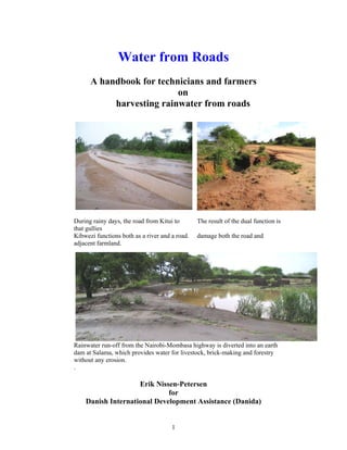
  • 1. Water from Roads A handbook for technicians and farmers on harvesting rainwater from roads During rainy days, the road from Kitui to The result of the dual function is that gullies Kibwezi functions both as a river and a road. damage both the road and adjacent farmland. Rainwater run-off from the Nairobi-Mombasa highway is diverted into an earth dam at Salama, which provides water for livestock, brick-making and forestry without any erosion. . Erik Nissen-Petersen for Danish International Development Assistance (Danida) 1
  • 2. 2006 Technical handbooks in this series : Titles Contents 1 Water for rural communities Lessons learnt from Kitui pilot projects 2 Water supply by rural builders Procedures for being rural contractors 3 Water surveys and designs Survey, design and cost of water projects 4 Water from rock outcrops Rock catchment tanks, masonry and earth dams 5 Water from dry riverbeds Wells, subsurface dams, weirs and sand dams 6 Water from roads Rainwater harvesting from roads 7 Water from small dams Ponds and small earth dams built manually 8 Water from roofs Various types of roof catchments for domestic use These handbooks can be obtained free of charge by either collecting them from the office of ASAL Consultants Ltd., or by paying through bank transfer the cost of sending the manuals by courier. For further details, please contact: asal@wananchi.com with copy to asalconsultants@yahoo.com Published by ASAL Consultants Ltd. for the Danish International Development Assistance (Danida) in Kenya Text, sketches and photos by Erik Nissen-Petersen Computer drawings by Catherine W. Wanjihia Editing and proofs by Prof. Elijah K. Biamah, Amin Verjee and Steen S. Larsen Printer Printwell Ind. Ltd., P.O. Box 5216-0506, Nairobi, Kenya Website by Edwin Ondako Distribution by ASAL Consultants Ltd. P.O. Box 739, Sarit 00606, Nairobi, Kenya asal@wananchi.com asalconsultants@yahoo.com Fax/Tel : 254 020 2710296 and 4766144 Mobiles: 0733 619 066 and 0722 599 165 Website : www.waterforaridland.com  Copyright. The copyright of this handbook is the property of the Royal Danish Embassy in Kenya. Downloading from the internet and photocopying of the handbooks is permitted provided the source is acknowledged. 2
  • 3. Contents Page Acknowledgement ………………………………………………………… iv Foreword ………………………………………………………………….. v Technical vocabulary …………………………………………………….. vi Measurements and conversions …………………………………………. vii Chapter 1. Damage by road run-off water ………..…………….. 1 1.1 Road damage by run-off ……….…………………………………. 1 1.2 Loss of people and livestock ……………………………………… 2 1.3 Gullies made by culverts ……………………………………….…. 3 1.4 Volume of rainwater running off roads …………………………… 4 1.5 Benefits from rainwater running off roads ………………………… 5 Chapter 2. Earth dams ……………………………………………… 6 2.1 Murram pits ……………………………………………………….. 6 2.2 Small pans …………………………………………………………. 8 2.3 Large pans …………………………………………………………. 8 2.4 Ponds ………………………………………………………………. 9 2.5 Charco dams ………………………………………………………. 9 2.6 Hillside dams ……………………………………………………… 10 2.7 Valley dams ……………………………………………………….. 11 2.8 Tools and equipment for soil works ………………………………. 12 2.9 Analysis of soil samples …………………………………………… 13 2.10 Construction costs of earth dams ………………………………….. 14 2.11 References on earth dams …………………………………………. 14 Chapter 3. Water tanks ……………………………………………… 15 3.1 Advantages of water tanks …………………………………………. 15 3.2 Excavation of hemispherical tanks ………………………………. 15 3.3 Hemispherical tank built of burnt bricks ………………………….. 16 3.4 Hemispherical tank built of ant-hill soil, lime, sand and cement .... 19 3.5 Hemispherical tank built of ferro-cement ………………………… 23 3.6 Cylindrical underground water tanks …….……………………….. 26 3.7 Berkads …………………………………………………………….. 28 3.8 Rectangular water tanks ……….…………………………………… 33 3.9 References on water tanks …………………………………………. 33 Chapter 4. Subsurface dams ……………………………………………... 34 4.1 Water in sand reservoirs ……………………………………………. 34 4.2 Floodwater passing roads ………………………………………….. 34 4.3 Hand-dug wells ……………………………………………………. 35 4.4 Subsurface dams. weirs and sand dams ……………………………. 36 4.5 Subsurface dams built of soil ……………………………………… 37 4.6 Weirs ……………………………….……………………………… 39 4.7 Sand dams ……………………………….………………………… 40 4.8 Sand harvesting …………………………………………………… 44 4.9 Gold and gem stones from sand dams ……………………………. 45 4.10 References on subsurface dams, weirs and sand dams …………… 45 Chapter 5. Run-off farming …………………………………….… 46 5.1 Drainage from roads by engineers ………………………………… 46 5.2 Drainage from roads by farmers ………………………………….. 47 5.3 Soil bunds …………………………………………………………. 50 5.4 Gullies …………………………………………………………….. 51 5.5 Macro-irrigation …………………………..………………………. 55 5.6 References on run-off farming ……………………………………. 57 2
  • 4. Acknowledgments Much gratitude is due to Birgit Madsen of the Royal Danish Embassy in Nairobi for having taken a leading role in documenting the experiences of various techniques of creating low-cost water supply structures in the semi-desert, arid and semi-arid regions of the world. Many thanks are also due to Prof. Elijah Biamah, Steen Larsen and Amin Verjee, who assisted with proof-reading the text and editing, to Edwin Ondako who created the website and loaded this handbook and others onto it, and to Oliver D’Cunha, who managed the printing at Printwell Ind.Ltd.. Thanks are also due to the many engineers, technicians, artisans and self help groups who participated in several training courses and other assignments on small earth dams implemented by ASAL Consultants Ltd. for Danida, SIDA, UNDP, the EU and other organisations in a dozen countries over the last three decades. This handbook, Water from Roads, is one of a series of 8 publications on Water in Arid Lands, financed by the Danish International Development Assistance (Danida). To promote the simple technologies described in the handbooks, these can be read or downloaded free of charge from our website www.waterforaridland.com . Erik Nissen-Petersen Managing Director ASAL Consultants Ltd. P.O. Box 739, 00606, Nairobi, Kenya Tel/fax: +254 (0)20 2710296 Mobile: +254 (0)733 619066 / +254 (0)722 599144 Disclaimer The designs and construction procedures described in this handbook are based on the author’s experiences and observations over 30 years. The tanks and earth dams described herein, when properly constructed and maintained, have performed exceptionally well. However, local climatic, geological, seismic and soil conditions vary widely, as does the quality of materials and workmanship, and while the author and Danida are keen to encourage the replication of the ponds and dams described in this handbook, they cannot accept liability for the failure of a water harvesting system based on the designs and construction procedures described herein. 3
  • 5. Foreword This handbook on water from roads produced by Danida in Kenya is targeted at all organizations involved in road construction works and especially the Ministry of Roads and Public Works. Currently, all road construction works have no provision for the storage of run-off water generated from road drainage. This handbook then comes when road engineers have been trained and sensitized on the importance of safe disposal of run-off water from roads. Water from Roads as a handbook is expected to serve as a guide for road engineers and contractors who are involved in the design and construction of road drainage works. The handbook provides valuable technological advice for harnessing road run- off water. This handbook provides all the technical information required for the design and construction of all the types of earth dams, water tanks and subsurface dams. Also the handbook contains information on run-off farming. It is this understanding of the technical information contained herein that our roads could be designed better by providing viable alternative technologies options for harnessing road drainage. This handbook also provides alternative technologies for run-off water utilization. Mrs Elizabeth Mibey Principal Environmental Impact Assessment (EIA) Officer Ministry of Roads and Public Works 4
  • 6. TECHNICAL TERMS AND ABBREVIATIONS ASAL = Arid and Semi-Arid Lands ASALCON = ASAL Consultants Ltd. Batter = Gradient of a dam wall Bench mark (BM) = A fixed point for measurements Berm = Area between a reservoir borrow pit and dam wall Base = Foundation for a dam wall Borrow pit = An excavation from where soil is taken Bill of Quantities (BQ)= List of materials and labour, with costing Catchment = Area draining run-off water to a common point Centre line = An imaginary line through the centre of a crest at the upper level of the freeboard Contour line = Horizontal line connecting points of equal altitude Crawler = Bulldozer Crest = Top of dam wall Danida = Danish International Development Assistance Diaphragm = Blanket of soil on upstream side of embankment Downstream batter = Downstream slope of a dam wall Downstream toe = Downstream edge of a dam wall Draw-off pipe = Pipe draining water by gravity Embankment = Dam wall Evaporation = Water lost as vapour from a water surface EU = European Union Freeboard = Safety height of dam wall from maximum water level Gradient = Slope Hafir (Arabic term) = A type of earth dam for livestock and people Inselberg = A massive bare rock outcrop common in the tropics Impervious = Not letting water through Key (Cut-off trench) = Trench of clayey soil to prevent seepage Live fencing = Fence of vegetation, preferably thorny Murram = A clayey soil packed with stones found in laterite soil NIL = Cement slurry Seepage = Water seeping through soil Sediment = Soil deposited in reservoir Settlement = Soil compacting and shrinking due to weight SIDA = Swedish International Development Assistance Sill = Low concrete wall across spillway Siltation = Dam reservoirs being filled with silt Siphon = Pipe lifting water over a high point to a lower level SODIS = SOlar DISinfection (of water) Spillway = Overflow channel discharging excess floodwater Storage ratio = Volume of water in relation to volume of soil Turbid = Muddy, unclear water carrying sediment Throw-back = Length of a reservoir full of water Topographical = Relating to the shape and height of the land UNDP = United Nations Development Programme Upstream batter = Upstream slope of a dam wall Upstream toe = Upstream edge of a dam wall Valley dam = Dam constructed in a valley with a straight embankment Washout = Section of a dam wall washed away by water 5
  • 7. ILLUSTRATION OF TECHNICAL TERMS Cut-through section of a three-dimensional sketch of a dam wall. MEASUREMENTS AND CONVERSIONS Length 1 metre = 3.28 feet 1 km = 0.62 miles Area 1 acre = 4,047 m2 = 0.4047 hectares (ha) 1 ha = 10,000 m2 = 2.471 acres 1km2 = 100 ha = 247.1 acres Volume 1 litre = 1.75 pints = 0.22 Imp gallons (or 0.26 US galls) 1 m3 = 1,000 litres (l) = 220 Imp gallons (or 260 US gallons) 1 Imperial gallon = 4.550 l 1 US gallon = 3.785 l Weight 1 tonne = 1,000 kg 1 British ton = 1,016 kg 1 US ton = 907 kg Volumes and weight of materials 1 m3 water = 1,000 kg 1 m3 dry soil = 1,230 to 2,000 kg 1 m3 compacted soil = 2,180 kg, approximately 1 m3 loose gravel = 1,745 kg, approximately 1 m3 stones = 2,400 kg to 2,900 kg Exchange Rate Used in the Manual Ksh = Kenya Shillings Ksh 72/ = USD 1.00 (October 2006) 6
  • 8. Chapter 1. Damage by road run-off water 1.1 Road damage by run-off Rainy seasons are blessings for farmers but hard times for motorists. Streets get flooded and impassable in towns due to blocked or under-dimensioned sewage systems. In the countryside, villagers may be cut off from the rest of the world due to deep holes filled with water and mud, which vehicles cannot drive through. The photo shows the depth of such a hole in a road after the water has evaporated. Here the rainwater has cut a small gully on one side of the road. Since usually no repairs take place during rainy seasons, every additional rain shower will make the gully deeper. The following rain showers have now deepened and widened the small gully into a deep cut that runs halfway across the road and through the farmland until the flood reaches a riverbed. The rainwater continues to remove considerable amounts of murram from the road and soil from the farmland, which is eventually transported to the sea via riverbeds, where it chokes fish, coral reefs and damages the marine ecology. A few more rain showers have now extended the gully right across the road and made it impassable. The only way of by-passing the gully is to drive over the farmer’s land on the higher side of the road, where vehicles have cut a deep track. No crops will ever grow there again. 7
  • 9. A road-grader has made a cut-off channel to divert run-off water from a road to a field. While this preserves the road, it damages the field, because the run-off water will create a gully stretching all the way from the road to the nearest riverbed. After a few years, the run-off water from the road will have deepened and widened a small gully in a fertile farmland to a bare valley where all the top soil has been eroded. Only hardy thorny scrubs can grow there. Where no preventive action is taken, a small gully may turn into a desolate moon landscape as seen in the photo. In this way, thousands of acres of fertile farmland are being washed away every year by uncontrolled rainwater running off roads. Another hazard created by rainwater running off roads is that some people and animals lose their lives, while trying to cross a road over a riverbed flooded by rainwater. 1.2 Loss of people and livestock Often rainwater comes as a flash flood several metres high, which carries uprooted trees and drowned animals – and sometimes drowned people - into the brown maelstrom of flooded riverbeds. The photo shows the damage by erosion to a low bridge after a flood has passed over it. This handbook explains in simple terms, how other people have stopped the erosion process and improved their living standards. 8
  • 10. 1.3 Gullies made by culverts Culverts are concrete rings laid as drainage pipes under roads at their lowest points. The culverts drain run-off water from the upper side of a road to a riverbed on the lower side of the road. The photo shows a series of concrete check dams along the newly built Nairobi- Mombasa highway. The check dams reduce the velocity of water before it enters the culvert seen in the left lower corner. On the other side of the road, the culvert discharges the water into a small ditch which spills the water onto grazing land without any soil protection. This ditch will turn into a deep gully after some rainy seasons and the topsoil and grass will be washed away. In the near future, the Maasai will have to graze their livestock elsewhere. This photo, of the same road near Sultan Hamud, gives a good impression of the huge volumes of run-off water from roads after a small rain shower. Luckily, this water is discharged into a riverbed without any erosion. This photo shows a culvert near Arusha that discharges run-off water into a ditch that will either turn into a gully or a riverbed after a few more rainy seasons. 9
  • 11. 1.4 Volume of rainwater running off roads The volume of rainwater running off from a 1 km long murram or tarmac road from a rain shower of 30 mm, can be estimated as follows: Road area: 1,000 m long and 4 m wide Road surface: Murram or soil Run-off efficiency: 80% Rainfall: 30 millimetres 1,000 m x 4 m x 80 x 30 mm = 96,000 litres = 96 cubic metres from 1 km road 100 Bearing in mind that the average annual rainfall in a season is about 600 mm in most ASAL regions, the total annual volume of run-off water from a 1 km long murram road is: 1,000 m x 4 m x 80 x 600 mm = 1,920,000 litres = 1,920 cubic metres 100 Considering that one local Zebu cow consumes about 20 litres of water in a day, then 185 local cows can be watered every day in a year (1,920,000 litres minus 30% loss (576, 000 litres) = 1,344,000 litres / 20 litres / 364 days = 185) from only 1 km of murram road. This example shows clearly that roads can supply huge volumes of water for livestock, irrigation, forestry, construction works, etc., provided the harvested water can be stored until it can be used in the following dry season. If the stored water is intended for domestic use, it can be treated using grounded seed from Moringa stenopetala to settle the dirt in the bottom of a container. Thereafter the water should be sterilised either by boiling or by the Sun’s ultraviolet rays that can destroy all bacteria in water filled in transparent bottles and exposed to 6 hours sunshine. Run-off water from the Kanziku road in Kitui has been harvested into this pond, which was made by scooping out a depression and placing the soil as a dam wall on the lower side of the excavation. Hopefully, the woman will treat the water she is drawing, before it will be used for domestic purposes. 10
  • 12. 1.5 Benefits from rainwater running off roads As shown on the previous page, the 1,344 cu.m. run-off water from 1 km of road can water 185 local cows every day in a year, while taking into account that 30% of the water may be lost due to evaporation or seepage. Besides watering livestock, the water could also be used for other purposes, such as: 1. Tree nurseries, woodlots, orchards and vegetative fencing of fields and homesteads, which provide income from sale of tree seedlings, timber, firewood, fruits, etc. 2. Manufacturing of burnt bricks, concrete blocks, culverts and other building materials that can be sold. 3. Sale of water to neighbours for watering their livestock, construction works, etc. 4. Raising ducks, geese, fish and bees in or near open water reservoirs. 5. Sale of sand harvested from weirs and sand dams in gullies and riverbeds. 6. Recharge of hand-dug wells near subsurface dams, weirs and sand dams in riverbeds from where domestic water can be drawn. 7. Using run-off water from tarmac roads for domestic use is not advisable due to the risk of contamination by tar, oil, rubber, etc. 8. Increased agricultural production from fields irrigated by road run-off water. Two examples of school boys earning cash for their schooling: Harvesting sand for sale from a sand dam Assisting water vendors in bringing built in a gully near Lake Victoria. The empty jerrycans to a water point near construction cost of 10 sand dams was Voi. recovered from sale of sand in 1 ½ years. The next chapters will describe four types of rainwater harvesting from roads, namely earth dams, tanks, subsurface dams and run-off farming, which farmers can construct themselves for a minimum of investment. 11
  • 13. Chapter 2. Earth dams The most common technique for harvesting run-off water from roads is to store the harvested water in reservoirs built of soil. The construction cost consists only of labour to excavate and transport soil. There is no need to purchase cement or reinforcement iron from hardware shops. Several types of soil structures that can be constructed successfully by farmers are described in the following chapters. 2.1 Murram pits Murram pits, also called borrow pits, are always situated along roads and are easy to convert into water reservoirs, because only excavation of one or two trenches is required. However, before digging the trenches, it is advisable to discuss the issue with the local authorities. Murram pits are found along most roads, because the material (murram) excavated from them is used for building the roads. Whenever a road is re-carpeted with murram, the existing pits are either widened, or new murram pits are excavated. In any case, the floor of murram pits is usually either impermeable laterite or rock, through which there is hardly any seepage. If the walls or the floor of a murram pit are stony they may allow some seepage but that A murram pit along a road in Kitui can be sealed by plastering a mixture of clayey soil and lime onto the leaking parts. The run-off water from a road is diverted into a murram pit by excavating a trench reaching upwards from the murram pit to the ditch running along the road. To prevent sedimentation of the water reservoir in the murram pit, the trench should have a gradient of about 3 cm for every 100 cm. A gradient of 3:100 can be measured by levelling a spirit level on a 300 cm long timber having a leg being 9 cm long. This photo shows a cut-off trench that has been cut by a road grader for the purpose of diverting run-off water from the road into an adjacent field. Similar trenches can be excavated by hand, or ox-scoops, to divert rainwater into murram pits. 12
  • 14. When a murram pit has been filled with rainwater running off a road, the surplus water must be discharged over a spillway to avoid damage to the water reservoir. The height of spillways is important. If a spillway is too low, the maximum storage capacity of the water reservoir is wasted. If a spillway is too high, the lowest part of the wall will not be able to withstand the water pressure and it will be washed away thereby destroying the water reservoir. Preferably, the surplus water from a filled up murram pit should pass over a spillway that diverts the water back to its original course of discharge. In practice, the optimal height of spillways and the discharge of surplus water from murram pits can be found by heighten the spillway in stages. Spillways should always be protected by The side of a spillway protected by stones large stones packed with smaller stones into the floor and sides of the spillway to prevent erosion and ensure that the final height of a spillway is maintained. Water can be drawn from murram pits in many ways depending on the usage of the water. A girl filling jerrycans with water from a murram pit for domestic use. Two boys pumping water from a murram pit for irrigation of vegetables using a Money-maker foot pump costing about Ksh 5,000. 13
  • 15. 2.2 Small pans Pans are natural depressions without any dam walls around their water reservoirs. Pans were scooped out by elephants long time ago whereas murram pits are man made. Local people call these pans silanga ya ndovu, meaning elephant dams. Rainwater running off roads can be diverted into pans by excavated trenches, or along stone bunds, having a gradient of about 3:100 as described above. A small depression next to a road at Mbuinzau at Kibwezi has been converted into a pan by building a “speed bump” across the road, which diverts run-off water into the pan. Please note that the downstream side of the pan has been eroded by surplus water due to lack of a spillway covered with stones. A small pan next to a road at Kibwezi. 2.3 Large pans Large pans for storage of run-off water from roads and the annual floods from Angola, are common water sources in the extremely flat land of Ovamboland in Northern Namibia. The pans are used for raising fish, watering livestock and domestic uses as well. Deep pans in the Sudan are called hafirs. An excavated pan in northern Namibia that harvests run-off water from roads. An old pan being desilted manually in Taveta, for Food-for-Work, apparently without a proper workplan. A pan built recently by crawlers in the flat land of Taveta financed by TTAP/Danida. 14
  • 16. 2.4 Ponds Ponds are small earth dams that are made by scooping out soil and using the soil to construct a dam wall on the lower side of the water reservoir. There are three main types of small earth dams namely: Charco dams, hillside dams and valley dams. These dams are described in detail in another handbook of this series, namely Water from Small Dams, and will therefore only be described briefly in this handbook. 2.5 Charco dams Charco dams are suitable where run-off from roads spill over onto flat land, preferably with silty or clayey soils. The best design for charco dams resembles a calabash cut in half for scooping and pouring water as shown in the photo below. A calabash cut in half. Plan and profiles of a charco dam A charco dam in Tanzania. Charco dams and other small dams can be constructed in stages during dry seasons, when manual labour is available. Alternatively, neighbours who want to draw water from somebody else’s dam can be requested to scoop out and transport one wheelbarrow of soil for every jerrycan of water they want to carry home, or the water can be sold for cash and used to hire contract labourers for deepening a dam. At every stage, the water reservoir can be made deeper and the dam wall higher from soil excavated from the reservoir. This process can be continued until the dam can hold enough water throughout the year. Cross sections of a charco dam showing the first and last stage of excavation works. 15
  • 17. 2.6 Hillside dams Hillside dams are suitable where run-off water from roads can be diverted onto sloping land or hillsides. These dams have an oval-shaped water reservoir with a semi-circular dam wall on the lower side of the reservoir. A hillside dam at Lukenya along the Nairobi - Mombasa highway. Plan and profiles of a hillside dam. Another hillside dam at Salama on the same highway. Hillside dams must have a spillway at each end of the curved dam wall in order to discharge surplus water when the reservoir is full. The two spillways should be at the same horizontal level in order to discharge surplus water safely. A horizontal line can be sighted along the two water levels in a circular transparent hosepipe filled halfway with water. Spillways must be reinforced with large stones interplanted with grass at the dam wall to prevent Sighting along the two water levels in a erosion by over-flowing water. circular transparent hosepipe filled halfway with water, gives an exact Also the floors of spillways should be covered horizontal line. with stones and grass and interplanted with types of grass having many runners and long roots. 16
  • 18. 2.7 Valley dams Valley dams are suitable where run-off water from roads is discharged into valleys. Valley dams have straight embankments (dam walls) with a wide spillway at each end of the embankment. Although valley dams require less excavation work than charco and hillside dams, they are vulnerable and could be washed away by unexpectly large volumes of run-off water. Considering the unpredictable weather pattern created by global warming, many valley dams have been destroyed by extremely high rainfall. Plan and profiles of a valley dam. Source: Water from ponds, pans and dams by the author for RELMA/Sida in Kenya, 2005. Construction of the designed dam by manual labour. 17
  • 19. 2.8 Tools and equipment for soil works Plots having a volume of The “owners” of the plots excavate the soil and load it 1 cubic metre of soil are onto wheelbarrows. Women transport the soil to the dam pegged out and distributed. wall, off-load it and compact it manually. Various sizes of plots all with the same volume of 1 cubic metre of soil. An ox-scoop made of 4 mm steel plate; with a plough and ox-scoop, two men and two oxen can excavate and transport more soil than 10 able-bodied men. 18
  • 20. 2.9 Analysis of soil samples It is important to analyse samples of soil that shall be used for construction of dams in order to minimise seepage losses. Naturally, the most clayey soil found on a dam site should be used for those parts of a dam wall that should be as impermeable as possible. Sandy soils should be used on the downstream side of a dam wall where weight, and not impermeability, is required. A soil test that gives the percentage of clay, silt, sand and gravel can be carried out using a transparent bottle as follows: Fill a transparent bottle 1/3 with a soil sample and 1/3 with water. Add a pinch of salt. Shake the bottle vigorously for 1 minute. Leave it for 1 hour, then shake again. After 4 hours, measure the thickness of each layer in the bottle. The upper layer is clay followed by silt, sand and gravel at the bottom. Find the percentage of each layer by measuring its thickness against the total thickness of the soil sample and multiply by 100. Another simpler but less accurate method is to remove the caps and bottoms of some transparent plastic bottles. Fill the bottles halfway with soil and top up with water. Keep on adding water while watching the speed with which the water infiltrates the soil. Soil with the least infiltration has the highest clay content and is therefore the most suitable soil to use for the impermeable parts of a dam wall and its reservoir. Source: Water from ponds, pans and dams by the author,for RELMA/Sida in Kenya, 2005. 19
  • 21. 2.10 Construction costs of earth dams The four types of earth dams listed below have different construction costs depending on the construction method and the water-to-soil ratio. a) The construction method relates to whether the excavation is done: 1) Manually with shovels and wheelbarrows costing about Ksh 100/cu.m. soil. 2) With draught animals, scoops, ploughs and carts, costing about Ksh 60/cu.m. 3) Hiring a farm tractor with a plough and scoop costing about Ksh 80/cu.m. 4) Hiring a crawler (bulldozer) costing about Ksh 300/cu.m. soil. b) The water-to-soil ratio depends on the type of dam, because the volume of water: 1) A pond is equal to the volume of excavated soil, therefore the ratio is 1:1. 2) A charco dam is equal to the volume of soil, therefore also 1:1. 3) A hillside dam is 1.5 times more than the excavated soil, therefore 1.5:1. 4) A valley dam is 3 times more than the excavated soil, therefore 3:1. Although valley dams have the lowest construction cost per m3 soil, because they can store about 3 times more water than the excavated soil, they have a much higher rate of failure than other types of earth dams. Type of Construction Reservoir Water Excava- Cost Total Cost per dam method volume to soil ted soil per cost cu.m. of cu.m. ratio cu.m. cu.m. Ksh. water storage Ksh. Excava- ted pond Manual 100 1:1 100 x 100 = 10,000 100 Charco Manual 500 1:1 500 x 100 = 50,000 100 dams Tractor 500 1:1 500 x 80 = 40,000 80 Oxen 500 1:1 500 x 60 = 30,000 60 Hillside Manual 500 1.5:1 333 x 100 = 33,300 66 dams Tractor 500 1.5:1 333 x 80 = 26,640 53 Oxen 500 1.5:1 333 x 60 = 19,980 40 Valley Crawler 5,000 3:1 1,670 x 300 =501,000 100 dams Manual 5,000 3:1 1,670 x 100 =167,000 33 Tractor 5,000 3:1 1,670 x 80 =133,600 27 Oxen 5,000 3:1 1,670 x 60 =100,200 20 Source: Water from ponds, pans and dams by the author, for RELMA/Sida in Kenya, 2005. 2.11 References on earth dams Design and Construction of Small Earth Dams. Nelson, K.D. Australia 1985. Field Engineering for Agricultural Development. Hudson, Oxford, UK. Small Earth Dam built by Animal Traction. Nissen-Petersen, E., Danida Kenya 1990. Small earth dams. Brown, L.N. University of California, USA 1965. Water from ponds, pans and dams. Nissen-Petersen, E. RELMA/Sida Kenya 2005. Water from Small Dams. Nissen-Petersen, E. Danida Kenya 2006. 20
  • 22. Chapter 3. Water tanks 3.1 Advantages of water tanks. In regions with sandy soils, much water is usually lost from seepage in earth dams, and additional water is also lost by evaporation due to the large surface area of the water reservoirs. Furthermore, earth dams have other disadvantages such as siltation of reservoirs due to lack of proper soil conservation, erosion by livestock watered in the reservoirs, water-borne diseases and vector carried diseases. Since it is difficult and expensive to reduce these disadvantages of earth dams, it may be more applicable to build water tanks. Although the capacity of water tanks is smaller than earth dams, they have several advantages, such as: 1) Seepage can be eliminated by lining water tanks with clay, anthill soil, burnt bricks, concrete blocks, ferro-cement or butyl rubber sheets. 2) Evaporation can be greatly reduced by roofing water tanks with live vegetation on wires, iron sheets, concrete covers or ferro-cement domes. 3) Siltation can be eliminated by excavating and regularly emptying silt traps. 4) Contamination by livestock and vectors can be avoided if the tanks are covered. A number of well-functioning water tanks for harvesting rainwater run-off from roads are described in the following pages. A common feature for all the tanks is that none of them have a square or rectangular shape because these shapes always tend to crack. Water tanks should always have a hemispherical or a cylindrical shape, because these shapes distribute equally the external and internal pressures on the wall, thereby eliminating the risk of cracks due to uneven tension. 3.2 Excavation of hemispherical tanks. Another common feature is that the tanks are built against the wall of solid soil exposed by the excavation works thereby ensuring a solid support of the entire tank wall. Excavation of hemi- spherical tanks is made accurately by using a wire with the desired radius, tied to a peg in the centre column. The centre column is removed as the last part of the excavation. 21
  • 23. 3.3 Hemispherical tank built of burnt bricks. Lay the first brick on its side in the centre of the tank. Thereafter lay the following bricks on their sides as a spiral winding their way up towards the ground level. For every metre or so, moisten the bricks and compact mortar into the spaces between the bricks, with a mixture of 1 part cement to 4 parts of coarse sand (1:4). When the laying of bricks has reached ground level, a centre pipe is erected and a radius wire is tied onto it for building the circular foundation wall, which prevents children and animals falling into the tank. A silt trap built in front of the inlet. Two gaps are made opposite each other to cater for the inlet of rainwater and outlet for water overflowing the tank. Barbed wire is then wrapped tightly in a spiral around the outside of the tank wall above ground level, with a spacing of 10 cm. Chicken mesh is thereafter nailed onto the inner wall of the tank for additional reinforcement. The internal and external walls are then plastered with 1:4 mortar and made water-proof with NIL (cement slurry) the same day. 22
  • 24. A centre post made of a PVC pipe filled with concrete is erected in the centre onto which barbed wire is tied to form a roof. A lockable manhole is fitted on the roof. The tank is coated with a weather- proof mixture of 1 part of cement to 10 parts of lime mixed with water. Water can be drawn from the tank by a bucket in a rope or another simple lift. Formula for calculating the volume and surface area of a hemispherical tank The volume of a hemispherical water tank can be calculated using the following formula: 2/3 x ‫ ח‬x r3, or simplified to: 2/3 x 22/7 x radius x radius x radius = Volume. The volume of this tank: 2/3 x (22/7 x radius 2.17 m x radius 2.17 m x radius 2.17 m) = 2/3 x (22/7 x 10.218) = 2/3 x 32.11 = 21.41 cu.m volume The surface area of this tank can be calculated using the formula of: 2 x ‫ ח‬x r2 , that can be simplified to: 2 x 22/7 x radius 2.17 x radius 2.17 = 29.60 sq.m. + superstructure: d x ‫ ח‬x h: diameter 4.34 x 22/7 x height 0.8 = 10.91 sq.m Total inner surface area = 40.51 sq.m. Bill of quantities and cost of a 21 cu.m. hemispherical tank built of burnt bricks Description Unit Quantities Unit cost Ksh Total cost Ksh Labour cost Artisan Artisans 1 x 10 days 400/day 4,000 Labourers Labourers 3 x 15 days 200/day 9,000 Cost of labour 13,000 Materials Bags of cement 50 kg bags 25 600 15,000 River sand Tonnes 6 200 1,200 Crushed stones Tonnes 1 600 600 Burnt bricks 4”x 6”x 10” Units 1,170 5 5,850 Water Oil-drums 5 100 500 Y 12 twisted iron bars Lengths ½ 600 300 Barbed wire 20 kg rolls, g 12.5 1 3,000 3,000 Chicken mesh 3’ x 90’ x 1”, rolls 2 3,000 6,000 Nails, 2” Kg 5 100 500 Lime 25kg 3 400 1,200 uPVC, 4” sewage pipe Lengths 1 400 400 Cost of materials 34,550 Transport of materials Hardware lorries 3 tonnes 1 loads 3,000 3,000 Tractor trailer loads 3 tonnes 7 loads 900 6,300 Cost of transport 9,300 Total cost of a 21 cu.m. tank 56,850 23
  • 25. 4,330 (Internal Diameter) Barbed wire spaced at 550 mm 900 x 200mm Outlet Barbed wrapped outside and plastered (1:4) 20mm thick 1:3:6 Concrete in 570 640 260 360 100mm uPVC pipe GL MWL Inlet GL 4,300 310 310 120 60 600 200 140 Silt trap 2 nos Y12 twisted iron bars in column Chicken wire nailed inside 300 x 300 x 150 footing and plaster (1:3) 30mm thick 150mm Burnt brick wall SECTION A-A (mm) 90 0 Wall Manhole 0 70 360 640 260 360 130 130 A A 680 680 130 130 4,730 PLAN (mm) Cross section and plan of a 21 cubic metre tank built of burnt bricks. 24
  • 26. 3.4 Hemispherical tanks built of anthill soil, lime and cement As seen above, the cost of building a water tank of burnt bricks with a storage volume of 21.4 cu.m. is Ksh 56,850, equivalent to Ksh 2,656 er cubic metre storage volume. The construction cost can be reduced by using powdered anthill soil as a part substitute for cement and burnt bricks. The best of the two tanks described below has a storage volume of 48 cu.m. and was constructed for Ksh 34,360, equivalent to Ksh 716 per cubic metre storage volume. However, this saving of Ksh 1,940 per cu.m. as compared against the above brick tank, comes with a higher cost of maintenance and repair. Nevertheless, it is an affordable tank to construct for most rural people. The cost of maintenance and repair can be recovered using the water for cash generating activities, such as growing and selling vegetables and tree seedlings, making and selling burnt bricks, selling water, watering livestock, etc. A dozen tanks were built of various mixtures of powdered anthill soil, lime, murram and cement 20 years ago by the author in Mutomo in Kitui District. A recent follow- up on these tanks showed that some of the tanks are still performing well after two decades even despite lack of maintenance. Unfortunately, the records for the mixture ratios are lost and forgotten. This tank was built of the cheap materials mentioned above. 20 years of neglect have not weakened the tank. A representative of RELMA/Sida is admiring the inflow channel which has not been eroded by inflowing water. This picture shows another one of those old tanks built of cheap materials for harvesting run-off water from a road. Only the surface of the plaster along the water level has eroded slightly. There is no sign of the cone of sisal poles that prevented people and animals from falling into the tank. 25
  • 27. Two water tanks were built of anthill soil, lime, sand and cement during a training course at Makaani Primary School at Kibwezi in 1998. 1) The tanks were excavated using a radius wire that was 290 cm long and their volume was calculated as follows: 2) The radius of each tank: 290 cm minus 6 cm of plaster = 284 cm radius 3) The volume of each water tank was calculated using the formula of: 2/3 x ‫ ח‬x r3 simplified to: 2/3 x (22/7 x radius x radius x radius) = Volume. 4) The volume of this tank: 2/3 x (22/7 x radius 2.84 m x radius 2.84 m x radius 2.84 m) = 2/3 x (22/7 x 22.91) = 2/3 x 72.00 = 48.00 cu.m volume 5) The surface area of this tank can be calculated using the formula of: 2 x ‫ ח‬x r2 that can be simplified to: 2 x 22/7 x radius 2.84 x radius 2.84 = 50.70 sq.m. plus superstructure: d x ‫ ח‬x h = 5.68 x 22/7 x height 0.8 = 14.28 sq.m Total inner surface area 64.98 sq.m. ============================ Two types of plaster Anthills were broken into particles that could pass through a sieve made of coffee mesh. a) The 6 cm plaster for one tank was made of: 4 parts anthill soil 1 part cement 2 parts lime 6 parts river sand b) The 6 cm plaster for the other tank was made of: 20 parts anthill soil 2 parts cement 1 part lime 18 parts river sand A woman sieving anthill soil. The 6 cm thick plaster was reinforced with chicken mesh nailed to the first coat of 3 cm plaster. After 14 days of curing the plaster was coated with bitumen paint. A visit to the tanks three years later showed that the plaster mixture (a) above was the most superior, although the inflow of water had eroded part of the plaster due to a complete lack of maintenance by the school, its pupils and parents. 26
  • 28. 140 5520 140 20 40 40 20 1750 360 260 640 360 900 x 200mm Inlet 100mm uPVC pipe with 500 Silt trap concrete (1:2:4) and 2 nos Outlet GL MWL Y12 iron bars GL 200 500 200 200 200 3" 500 4 GI pipe 600mm long 40mm thick antihill clay plaster for ladder 500 2800 500 300 x 300 x 150 Footing 500 SECTION A-A (mm) 90 0 Manhole 0 360 260 640 360 70 130 A A 680 130 140 140 20 40 5520 40 20 PLAN (mm) Cross section and plan of 48 cu.m. water tank built of anthill soil, lime, sand and cement 27
  • 29. Bill of quantities and cost of the best 48 cu.m. tank built of anthill soil, lime, etc. Description Unit Quantity Unit cost Ksh Total cost Ksh Anthill soil Tonnes 7 300 2,100 Cement 50 kg bags 5 600 3,000 Lime 25 kg bags 3 300 900 Crushed stones Tonnes 1 600 600 River sand Tonnes 7 200 1,400 Burnt bricks Numbers 300 5 1,500 Chicken mesh 3 ft. x 90 ft. x 1” 3 rolls 3,000 9,000 Barbed wire 20 kg rolls, g 12.5 1 roll 3,000 3,000 PVC pipe 3 metres of 4” 1 length 400 400 Iron bars 3 metres of Y12 1/2 length 600 300 Nails 5 kg of 2” 100 500 Water 7 oil drums 100 700 Artisan 1 artisan 10 days 400 4,000 Labourers 3 labourers 15 days 200 9,000 Total 36,400 The first ground tanks for harvesting rainwater from roads and compounds were roofed with corrugated iron sheets tied onto galvanized iron pipes in 1983. Since goats and cattle could smell the water, they walked on the roofs and damaged them. The iron sheet roofs were therefore replaced by sisal poles arranged in a pyre and held together with an old tyre at the top. Passion fruit and lupher plants were grown on barbed wire wrapped around the sisal poles. 28
  • 30. 3.5 Hemispherical tanks built of ferro-cement Some 100 hemispherical water tanks with a storage volume of 60 cu.m. and 90 cu.m. were built of ferro-cement for roof and ground catchments by the Danida funded Mutomo Soil & Water Conservation Project in Kitui in the 1980s. The ferro-cement tanks are still in good shape but the roofs, made of corrugated iron sheets nailed onto timber, collapsed after some years. The collapsed roofs could easily and cost-effectively be replaced with domes made of ferro-cement, but no-one has taken on this responsibility. A USAID Peace Corps Volunteer replicated and enlarged the volume these hemispherical tanks in many places in Kenya. Many of these larger than normal tanks have cracked because the usual the reinforcement of barbed wire and chicken mesh is insufficient when the storage volume exceeds 100 cu.m. Some of these large tanks have been rehabilitated by building a new tank inside the damaged ones. The 60 cu.m tanks were constructed as follows: A peg was hammered into the centre of the tank, and a wire having a length of 312 cm was tied to the peg. This radius wire was used to guide the builders in getting the correct hemi- spherical shape. The centre column was removed after the hemispherical shape was completed. The excavated wall of soil was plastered with a 3 cm thick coat of mortar, with a mortar mixture of 1:3. It had to be completed in one day. The next day, the barbed wire and chicken mesh were nailed to the coat of mortar applied the day before. The following day, a second 3 cm coat of mortar was applied onto the reinforcement and made water-proof with NIL. Then the mortar was cured with water and kept under shade for 3 weeks. 29
  • 31. During the curing, a reinforced concrete beam was built onto the rim of the tank. Sisal poles were set in a groove of the beam to form a cone- shaped roof onto which barbed wire was wrapped around. A silt trap was made at the inflow to the tank and an overflow at the opposite side of the tank. Bill of quantities for a 60 cu.m. hemispherical tank built of ferro-cement Description Unit Quantity Unit cost Total cost Ksh Ksh Labour cost Artisan Artisans 3 x 14 days 400/day 16,800 Labourers Labourers 4 x 20 days 200/day 16,000 Cost of labour 32,800 Materials Bags of cement 50 kg bags 50 600 30,000 River sand Tonnes 14 200 2,800 Crushed stones Tonnes 1 600 600 Burnt bricks, 4”x 6”x10” Units 800 5 4,000 Water Oil-drums 45 100 4,500 Y 12 twisted iron bars Lengths 1 600 600 Barbed wire 20 kg rolls, g 12.5 5 3,000 15,000 Chicken mesh 3’ x 90’ x 1”, rolls 3 3,000 9,000 Galvanized ceiling nails Kg 5 130 650 Lime 25 kg 2 400 800 uPVC, 4” sewage pipe Lengths 1 400 400 G.I pipe 1½” 1 2,500 2,500 G.I fitting 1½” elbow, nipple 2 500 1,000 Mosquito mesh Plastic 1 100 100 Lockable door Steel, 3’ x 7’ (feet) 1 5,000 5,000 Galvanized coffee mesh Cu.m. 1 200 200 Cost of materials 1 200 200 77,350 Transport of materials Hardware lorries 7 tonnes 1 loads 5,000 5,000 Tractor trailer loads 3 tonnes 20 loads 900 18,000 Cost of transport 23,000 Total cost a 60 cu.m 133,150 tank The construction cost per cu.m. storage volume is: Ksh 133,150/ 60 cu.m. = Ksh 2,219/cu.m. 30
  • 32. 612 175 36 26 64 36 Silt trap Inlet 900 x 200mm Outlet Steel door Overflow 37 GL GL MWL 6 20 25 14 1:3:6 Concrete in 20 3" 4GI pipe 600mm 100mm uPVC pipe long for Ladder 20 2 nos Y12 twisted 363 iron bars in column 306 Filter Tap Footing 60 100 SECTION A - A (cm) 90 Manhole 70 36 26 64 36 60 Overflow 15 A A Tap 150 84 90 15 90 410 500 664 PLAN Standard design of a 60 cu.m. hemispherical water tank built of ferro-cement. In order to avoid hand pumps which require maintenance and spare parts occasionally, this design features a staircase leading down to a watertap from which water can be drawn by gravity from the tank. An additional advantage is that the staircase is also functions as a water reservoir. When surplus water is overflowing, it spills over onto the staircase. Water is drawn from the staircase by opening the steel door covering it and lifting a bucket of water out of the staircase. 31
  • 33. 3.6 Cylindrical underground water tanks Cylindrical tanks have been used for many years to harvest and store rainwater running off threshing floors from the sparse rains in the semi-desert areas of Botswana. Water is drawn with a bucket from the manhole on the cover of the tank as illustrated in this photo. A sketch showing the catchment area, which could have been a road as well, and the underground cylindrical tank built of burnt bricks. This type of cylindrical ground tank is used in the hot and arid Northern Namibia to store water for construction of schools. These tanks are also very suitable for collecting rainwater run-off from roads. These two cylindrical ground tanks were built of soil compressed blocks for fish farming at Machakos in Kenya in1980s. The tanks could also have been used for harvesting rainwater from roads. 32
  • 34. This tank was initially built for storage of ater for construction during a training course at Kibwezi in Kenya in 1997. Upon completion of the training, the tank was equipped with a silt trap and used for harvesting water from a road. This gigantic cylindrical ground tank was constructed for harvesting rainwater from a large concrete apron near Dodoma in Tanzania in 1992. The tank could also have been used as road catchment of rainwater. 33
  • 35. 3.7 Berkads Berkads are tanks that are excavated and lined with concrete blocks or ferro-cement in the semi-desert regions of Somaliland. Rainwater running off roads and hillsides is diverted into the berkads by soil bunds sloping upwards on hillsides until they reach a road. Most berkads have rectangular shapes with vertical walls that crack due to uneven external pressure of the soil when the berkads dry up. Water is drawn from berkads by either using the steps or the hand-dug well seen in the upper photo. This handbook promotes the much stronger oval-shaped berkads that has a shape as the silt trap in this photo. A newly made soil bund winds its way downwards though the bush from an unpaved road on a hillside. Walking down hill in the bund, a newly built berkad is reached at the end of the bund. The bund guides the run-off water into the silt trap before it enters the berkad. The excavated soil has been back- filled against the berkad. This could facilitate siphoning of water downhill for watering livestock or small-scale irrigation. 34
  • 36. 200 1950 200 Overflow Silt trap 350 8200 Large stones 200 GL MWL MWL 20mm internal plaster with nil 3000 Burnt brick wall thickness GL reduced from 200mm to 140mm 150 SECTION A - A (mm) 240 240 1450 4044 1450 MWL Excavated soil backfilled against the berkad GL GL 3000 Burnt brick wall 150 SECTION B - B (mm) 1950 750 8440 4100 B 4100 Excavated soil backfiled against berkad Large stones Silt trap Inlet A A 4044 1524 975 568 PLAN 35
  • 37. 12766 526 1000 1000 1000 1000 1000 1000 1000 1000 1000 1000 1000 1000 240 4326 4100 4340 B 2373 2317 2282 2065 2029 1718 403 A A 360 1246 315 1089 868 753 753 2063 4044 4746 1524 568 868 1089 1246 315 360 403 1718 2029 2065 2282 2317 2373 B PLAN OF EXCAVATION Marking a berkad on the ground can be made as follows: 1) Mark the highest place of the site for the inlet with a wooden peg. 2) Mark the lowest place of the site for the overflow with a peg situated 13 m from the inlet. 3) Draw a 13 m long nylon string between the two pegs. The string represents the centre line, called A-A, on the plan seen above. 4) Then place 14 pegs along the centre line with the intervals shown in centimetres below. The length of the berkad is 12766 mm = 1276.6 cm = 12.766 m = 12.77 m. 5) Starting from peg No. 1 at the inlet and measuring towards peg No. 14 (listed in the upper row) the measurements between the pegs are listed as cm in the middle row. 6) The figures in the lowest row are the distances from the centre line to the edge of the excavation. Use a long mason’s square to mark these measurements at an angle of 90 degrees to the centre line. 1 2 3 4 5 6 7 8 9 10 11 12 13 14 Total 53 100 100 100 100 100 100 100 100 100 100 100 100 24 1277 103 87 32 75 36 40 125 172 207 228 237 232 203 109 36
  • 38. Excavation of a berkad is done as follows: 1) First excavate the walls of the water reservoir by cutting along the line marked on the ground. 2) Thereafter excavate the wall vertically downwards using either a spirit level or a plumber’s rod, while also removing the soil within the wall. The excavated soil is dumped outside and around the lower end of the berkad from where it is back-filled after the wall is built. 3) The depth of the excavation should be 313 cm at the silt trap and the floor should be horizontal when measured from there. 4) When the reservoir has reached its final depth, the silt trap is excavated as shown in the design on the previous page. Concreting the floor of a berkad is done before building the wall. 1) First 7 cm thick layer of concrete 1:3:4 is compacted onto the excavated floor. Then a layer of weld mesh is laid onto the concrete. Thereafter a 7 cm thick layer of concrete 1:3:4 is compacted onto the weld mesh and smoothened. The work of concreting the floor must be completed in 1 day. 2) The concrete floor must be kept moist and covered with polythene, empty cement bags or grass for 3 weeks of curing. The wall of a berkad can be built of several types of materials depending on the soil structure of the excavation. 1) The options are: burnt bricks, concrete blocks, rubble stones or ferro-cement. A disadvantage of ferro-cement is that the wall must be kept moist and under shade for 3 weeks, otherwise the wall will be porous and might leak. 2) The technique of building a wall of ferro-cement is described on page 23. The inlet and silt trap can be made of the same material as the wall of a water reservoir. A soil or stone bund starts from the inlet and winds its way upwards with a gradient of about 3 degrees until it reaches a road or a rock outcrop capable of supplying sufficient run-off to fill the berkad with water. 37
  • 39. Bill of quantities and cost of a berkad Description Unit Quantity Unit cost Total cost Ksh Ksh Labour cost Artisan Artisans 1 x 14 days 400/day 5,600 Labourers Labourers 3 x 14 days 200/day 8,400 Cost of labour 14,000 Materials Bags of cement 50 kg bags 30 600 18,000 River sand Tonnes 9 200 1,800 Crushed stones Tonnes 3 600 1,800 Hardcore 2" to 6" Tonnes 7 200 1,400 Burnt bricks 4” x 6” x 10” Units 1,500 5 7,500 Water Oil-drums 20 100 2,000 Y 12 twisted iron bars Lengths 2 600 1,200 Barbed wire 20 kg rolls, g 12.5 1 3,000 3,000 Chicken mesh 3’ x 90’ x 1”, rolls 2 3,000 6,000 Galvanized ceiling nails Kg 4 130 520 Cost of materials 43,220 Transport of materials Hardware lorries 3 tonnes 1 loads 5,000 5,000 Tractor trailer loads 3 tonnes 13 loads 900 11,700 Cost of transport 16,700 Total Cost of a Berkad 73,920 38
  • 40. 3.8 Rectangular water tanks The only type of water tanks with square and rectangular shapes that can be recommended is seen in these two photos. The main features of the tanks are: a) the sides of the excavation must have a low gradient and be covered by butyl rubber or PVC sheets; b) the surface of the excavation must be smooth without any sharp objects that can puncture the sheets; c) the sheets covering the exca- vation must be glued together by experts, to ensure water-tightness. The disadvantages are: a) the sheets are expensive, b) the sheets can be punctured by livestock walking into the reservoirs, c) high evaporation losses, unless the tanks are covered with galvanized mesh attached to the center pole and onto which creepers can grow as shwon in the upper photo. 3.9 References on water tanks Ferrocement Water Tanks and their construction. Watt, S. IT Publications. UK. How to build cylindrical water tanks with domes. Nissen-Petersen, E.1990. How to build an underground tank with dome. Nissen-Petersen, E. 1900. How to repair various types of water tanks. Nissen-Petersen, E. 1990. How to build and install gutters with splash-guard. Nissen-Petersen, E 1990. How to build smaller water tanks and jars. Nissen-Petersen, K. 1990. Make your own plastic lined underground tank. Cherogony, KRA/RELMA 1999. Rain Catchment and Rural Water Supply. Nissen-Petersen,E. H&S, UK, 1982 Rainwater Catchment Systems. John Gould and Nissen-Petersen, E. ITDG, 1999. Water from Roofs. Nissen-Petersen, E. Danida Kenya, 2006. Water tanks with guttering and handpump by Nissen-Petersen, E. Danida, 1990. 39
  • 41. Chapter 4. Subsurface dams Most rainwater running off roads passes through gullies and riverbeds on its way to the sea. Some of that water can be trapped in one, or several, of the types of subsurface dams that are described briefly in this chapter and in detail in another handbook of this series: Water from Dry Riverbeds. 4.1 Water in sand reservoirs The main feature of subsurface dams is that their water reservoir is full of sand, where water is stored in the voids between the sand particles. 350 litres of water (35%) can be extracted from 1 cu.m. (1,000 litres) of coarse sand, due to its large voids. Fine- textured sand provides less than 190 litres (19%) of water from 1 cu.m. of sand, while only 50 litres (5%) of water may be extracted from silt due to its tiny voids. Subsurface reservoirs should therefore always contain as much coarse sand as possible. Storing of water in sand reservoirs has the following advantages: 1) Evaporation loss is minimal: Evaporation decreases proportionally with the water’s distance to the sand surface, and it is reduced to zero at a depth of 60 cm below the surface of the sand. 2) The water is not contaminated by large numbers of animals, because the water is ‘hidden’ below the surface of the sand. Some contamination does occur by passing animals etc, but it is limited to the area close to the sand surface, and no contamination occurs at the depth where the water is extracted. 3) Mosquitoes and other disease-spreading insects, as well as frogs and snakes, cannot live in water stored in sand reservoirs. Many gullies and riverbeds contain only fine-textured sand particles or no sand at all. In such cases, coarse sand can be trapped from floodwater by means of constructing a sand dam as explained in the next pages. 4.2 Floodwater passing roads Floodwater can pass roads in two ways; either under bridges, or over the roads. The latter are called drifts. Irish Bridges are concrete drifts that may function as weirs by blocking the underground flow of water in the sand, thereby creating a water reservoir upstream of the bridge, as seen in the photo. If Irish Bridges do not create water reservoirs, the upstream side of the bridges could be plastered with mortar or clayey soil, if the authorities allow. This photo shows water being piped from such a reservoir into a tank from where it is pumped up to a community. . 40
  • 42. 4.2 Hand-dug wells Hand-dug wells are the easiest and cheapest structures for the extraction of water from riverbeds containing sand. Wells can either be placed directly in a riverbed with a well-head protected against flood damage, or in a riverbank. The latter may require a perforated pipe to drain water from the riverbed into the well. It is always important to sink a hand-dug well in, or at, the deepest part of a riverbed, because that gives access to the most water. Such deep places can be identified by either: 1) Trees, such as wild figs and other trees that can only grow where water is available all year round. 2) Water holes excavated by people or animals that yield water for some time or throughout dry seasons. 3) Dowsing by gifted persons walking along riverbeds in dry seasons. 4) Probing by hammering long and retrievable iron rods into the sand of riverbeds. This technique can produce hydraulic profiles that show the correct places to sink wells and boreholes, and to construct weirs and subsurface dams as shown below. This longitudinal profile of a riverbed was drawn from measurements taken from probing with an iron rod at 20 metres intervals. The most suitable place for sinking a well is between probing number 2 and 4 on the left side of the profile because here the riverbed is deepest and will therefore provide most water. Hand-dug wells can be built in two ways depending on their depths. Shallow wells can be excavated to their final depth and then built from the bottom and upwards with burned bricks as shown in this photo. 1
  • 43. If hand-dug wells have to be sunk in deep sand, the “sinking” method should be used, because it is safe and economical. The well-shaft is made of curved concrete blocks that are reinforced together, atop a concrete foundation ring which is made in a circular groove cut into the sand of the well site. The concrete blocks are then mortared and tied with GI wires onto the foundation ring with steps built in the wall for easy entry and exit. When sand is scooped out of the shaft, it sinks into the sand. More blocks are then added and scooping repeated, and so on until the shaft has sunk to its final depth. Concrete culverts can also be used for sinking shafts but they are difficult to handle. Water can be drawn from hand-dug wells using a windlass, which requires only a new rope once in a while as seen in this photo from Namibia. Note the cattle troughs made of tree trunks. Wells can also be fitted with hand or motor pumps but that requires much more cash input, maintenance and repairs. 4.3 Subsurface dams, weirs and sand dams When a hand-dug well in a riverbed cannot supply the required volume of water, the yield of water can be increased by raising the water table in the riverbed by means of building a subsurface dam, a weir or a sand dam. These types of dams are built downstream of the well and onto a natural dyke that is located somewhere downstream of the well. The most potential natural dyke of the four dykes seen in this profile, is situated at the far left side of the profile. A subsurface dam, which was built of soil on that dyke, raised the water level 1.5 metres from the existing water level (Ext. WL) to the new water level (New WL) along a 500 metres long stretch of the riverbed. The subsurface dam increased the volume of extractable water from the riverbed by about 2,000 cubic metres. The construction cost was free community labour for 350 days only. 2
  • 44. 4.4 Subsurface dams, whose walls are built of soil subsurface dam walls built of soil consist of replacing the sand laying on an under- ground dyke with soil taken from the riverbanks. The dam wall made of soil prevents floodwater from infiltrating in the sand and seeping downstream in the riverbed. The trapped water can be extracted from a hand-dug well sunk into the deepest part of the riverbed. A longitudinal profile of a riverbed combined with a three dimensional view of a subsurface dam, whose wall of soil is built onto a natural dyke, and a hand-dug well sunk into the deepest part of the riverbed. Standard design and profiles of a subsurface dam built of soil. 3
  • 45. Construction of subsurface dams whose walls are built of soil: The base for the wall is cleared by removing all sand from the site in a stretch of about 2 metres wider than the base of the wall. The width of the base is marked onto the riverbed and excavated to a depth of 20 cm into the floor of clayey soil or laterite. The profile of the dam wall is marked onto the riverbanks. A key, 60 cm wide, is then excavated along the centre of the base and into the banks to a depth of at least 60 cm. Should layers of sand be found in the key, it must be deepened to 60 cm below any layer of sand. The dam wall is constructed of the most clayey soil found near the site. First the soil is compacted into the key, preferably with water. Then the wall is constructed, layer-by-layer, each 20 cm thick, of soil that is well compacted. The upstream and downstream sides are cut to 45 degrees slope and smoothened. If the soil found for building the key and dam wall is lacking in clay content, the upstream side of the dam wall should be plastered with a layer of clay or soil mixed with dung for the purpose of making it more water proof. When the dam wall is completed, the excavated sand is back-filled. Soil can be analysed in transparent plastic bottles without bottoms and caps. Place the bottles upside down in sand and fill the bottles halfway with soil samples and top up with water. The soil with the slowest seepage, seen in Soil No. 3, is the best for building dam walls, because it has the highest clay content. 4
  • 46. 4.5 Weirs Weirs are walls built of rubble stone masonry, or concrete, across riverbeds and into the riverbanks. Although the construction cost of weirs is higher than subsurface dams built of soil, their advantage is that the dam wall can protrude 50 cm above the level of sand in riverbeds, while dam walls for subsurface dams have to be 50 cm below the riverbed. The 1 metre difference in the height of sand in riverbeds provide a much larger storage capacity of water, which usually justifies the bigger construction cost. A longitudinal profile combined with a 3-dimensional view of a weir built into natural dyke and riverbank. A hand-dug well is sunk in the deepest part of the riverbed. A standard design and profiles of a weir with wing walls. The construction of this weir took 452 community working days, 105 bags of cement, 2 rolls of barbed wire, 15 tonnes of sand from the riverbed, 15 tonnes of crushed stones and 40 tonnes of large rubble stones. The construction cost was: Ksh 80,800 for survey, design and labour, Ksh 68,000 for materials and Ksh 15,300 for transport of materials. This amounts to a total cost of Ksh 164,100, plus an estimated value of Ksh 50,700 for local labour and materials. The total cost and value was therefore Ksh 214,800 in 2004. 5
  • 47. Construction of a weir consists of the following procedure: Remove the sand in a 2 metres wide stretch across the riverbed. Excavate the key to be 60 cm wide and 100 cm below any layer of sand found in the soil of the riverbed and riverbanks. The height of the wing walls above the riverbanks can be 60 cm only. Wash rubble stones and compact them into a 20 cm high layer of mortar mixture of 1 cement to 4 sand, which is laid in the bottom of the key along its whole length. Then lay 4 lengths of thick barbed wire in the key along its whole length for reinforcement of the dam wall. Continue laying 20 cm layers of mortar and compacting rubble stones into it. Another 4 lengths thick barbed wire are laid into the mortar at 20 cm intervals before the final height of the wall. The wall is built to 50 cm above the level of sand in the riverbed by applying mortar to flat rubble stones along the outer sides of the wall. Next day the space between the sides are filled with mortar and rubble stones. 4.6 Sand dams Sand dams are structures that can raise the level of sand and water to several metres height far upstream of the dam wall. Sand dams are much more complicated to design and construct than subsurface dams and weirs, because of the pressure made by floods and the elevated sand and water that press against the dam wall. As a matter of fact, most sand dams do not function well and many have been washed away by floods. However, one design has proved more successful than all the others and that is the ALDEV (African Land Development) design from the 1950s. The design criteria is based on the height of the spillway as shown on this sketch. 6
  • 48. The main feature of the ALDEV sand dam is that the spillway is only raised to about 30 cm height after floodwater has deposited sand to the level of the spillway. This procedure ensures that the reservoir will consist of coarse sand from where up to 35% of water can be extracted, which is 350 litres of water from 1 cu.m. of sand. The table below shows the percentage of water that can be extracted from the various types of silt and sand that are found in riverbeds. Silt Fine sand Medium sand Coarse sand Size mm <0.5 0.5 to 1.0 1.0 to 1.5 1.5 to 5.0 Porosity 38% 40% 41% 45% Water extraction 5% 19% 25% 35% The table shows that only 5% of water, which is 50 litres of water, can be extracted from 1 cubic metre of silt, while 35%, 350 litres of water, can be extracted from 1 cubic metre of coarse sand. Sand dams should be filled with coarse sand from where 350 litres of water can be extracted from every cubic metre of sand. The technique of extracting coarse sand from floodwater consists of raising the spillway by 30 cm high stages above each level of sand deposited by floods. A 30 cm high spillway traps the heavier coarse sand that rolls along the bottom of floodwater. Fine textured sand and silt, which is lighter and therefore floats in the upper layer of floodwater, will not be trapped by the spillway. When the first stage of a spillway has trapped coarse sand from a flood, a second phase of 30 cm height is added and so on until the sand dam has reached its designed height. 7