SlideShare ist ein Scribd-Unternehmen logo
1 von 10
LINE FOLLOWER ROBOT
This robot is designed to continuously follow a black line painted on a
bright surface or a white line on a dark surface and take the turns along
with the line automatically. For situations such as cross over where the
robot can have more than one path that can be followed, predefined path
must be followed by the robot.
Overview
Line Follower Robot
Hardware components required and their purpose
1. Arduino UNO board
2. IR Sensor
3. Comparator
4. DC motor
5. Motor driver IC (L293D)
6. Wheels
7. Power adopter
 Arduino UNO board: This is the brain of this robot in which the
program is loaded to do the required functioning and is interfaced
with sensors and the motor driver to make the system work as
required.
 IR sensor: This senses whether there is platform in front of the robot
or an edge is arrived and sends the appropriate signal to the
comparator.
 Comparator: This gets input from the sensor, compare it with
predefined voltage and send logic 1 to microcontroller if there is
detected a still platform and logic 0 if edge of platform is there.
IR Sensor Circuit
 DC Motor: This motor is controlled with DC voltages and can move
in forward and backward direction according to the polarity of the
voltage applied.
 Motor driver IC (L293D): Microcontrollers can’t supply the
current required by DC motor to run. So, to fulfill this requirement
these motor driver ICs are used.
DC motors with Driver IC
 Power adopter: This is used to give appropriate dc power supply to
microcontroller, driver IC sensors and the other passive components
of the robot.
 Wheels: In it three wheels are employed, two at rear end and one at
front end. Rear wheels are attached with the motors and also control
the steering of robot. Front wheel is the loose steered wheel which
moves in the direction of the pressure applied to it.
Block diagram
Block Diagram: Line Follower
Description
To make the robot follow the black line, IR sensors are employed with the
fact that black surface absorbs light and white surface reflects light.
The sensors are mounted on left front end and right front end of the robot
keeping the black line lies in between them. Until sensors are getting the
reflected light, the comparator sends logic 1 to the microcontroller and the
microcontroller in turn switches ON the motor associated with the sensor
and when any of the sensors comes up on the black line the
microcontroller stops the motor associated with that sensors and make the
robot to turn in the direction of the black line.
When the robot reaches end point and both the sensors are getting black
surface, robot stops.
Program:
/*left sensor attached to pin 0, right sensor attached to pin 2,
left motor attached to pin 5(+ve),6 and right motor attached to pin 7(+ve),8 and*/
int left_sensor=0;
int right_sensor=2;
void setup() {
pinMode(left_sensor, INPUT);
pinMode(right_sensor, INPUT);
pinMode(5, OUTPUT);
pinMode(6, OUTPUT);
pinMode(7, OUTPUT);
pinMode(8, OUTPUT);
}
void loop()
{
char value,v0,v2;
v0=digitalRead(0);
v2=digitalRead(2);
value=((v2<<2)|v0);
switch(value)
{
case 5
{
digitalWrite(6, LOW);
digitalWrite(8, LOW);
digitalWrite(5, HIGH);
digitalWrite(7, HIGH); //switch on both
break;
}
case 1: //RIGHT SENSOR'S OUTPUT
{
digitalWrite(5, HIGH);
digitalWrite(7, LOW);
digitalWrite(6, LOW);
digitalWrite(8, LOW);//switch on only LEFT motor move to RIGHT
break;
}
case 4: //LEFT SENSOR'S OUTPUT
{
digitalWrite(5, LOW);
digitalWrite(7, HIGH);
digitalWrite(6, LOW);
digitalWrite(8, LOW);//switch on only RIGHT motor move to LEFT
break;
}
case 0:
{
digitalWrite(5, LOW);
digitalWrite(7, LOW);
digitalWrite(6, LOW);
digitalWrite(8, LOW); //both stop
break;
}
}
}
Programming Digital I/O pins of Arduino UNO board:
 Each pin is controlled by three commands associated with it which are
designated as:
pinMode()
digitalWrite()
digitalRead()
 pinMode()
This configures the specified pin to behave either as an input or an output.
Syntax
pinMode(pin, mode)
Parameters
pin: the number of the pin whose mode you wish to set
mode: INPUT, OUTPUT.
Returns
None
Example
int ledPin = 13; // LED connected to digital pin 13
void setup()
{
pinMode(ledPin, OUTPUT); // sets the digital pin as output
}
void loop()
{
digitalWrite(ledPin, HIGH); // sets the LED on
delay(1000); // waits for a second
digitalWrite(ledPin, LOW); // sets the LED off
delay(1000); // waits for a second
}
 digitalWrite()
Write a HIGH or a LOW value to a digital pin.
If the pin has been configured as an OUTPUT with pinMode(), its voltage will
be set to the corresponding value: 5V (or 3.3V on 3.3V boards) for HIGH, 0V
(ground) for LOW.
Syntax
digitalWrite(pin, value)
Parameters
pin: the pin number
value: HIGH or LOW
Returns
None
Example
Sets pin 13 to HIGH, makes a one-second-long delay, and sets the pin back to LOW.
int ledPin = 13; // LED connected to digital pin 13
void setup()
{
pinMode(ledPin, OUTPUT); // sets the digital pin as output
}
void loop()
{
digitalWrite(ledPin, HIGH); // sets the LED on
delay(1000); // waits for a second
digitalWrite(ledPin, LOW); // sets the LED off
delay(1000); // waits for a second
}
 digitalRead()
Reads the value from a specified digital pin, either HIGH or LOW.
Syntax
digitalRead(pin)
Parameters
pin: the number of the digital pin you want to read (int)
Returns
HIGH or LOW
Example
int ledPin = 13; // LED connected to digital pin 13
int inPin = 7; // pushbutton connected to digital pin 7
int val = 0; // variable to store the read value
void setup()
{
pinMode(ledPin, OUTPUT); // sets the digital pin 13 as output
pinMode(inPin, INPUT); // sets the digital pin 7 as input
}
void loop()
{
val = digitalRead(inPin); // read the input pin
digitalWrite(ledPin, val); // sets the LED to the button's value
}

Weitere ähnliche Inhalte

Mehr von UVSofts Technologies (12)

Basic standard calculator
Basic standard calculatorBasic standard calculator
Basic standard calculator
 
Password based door locksystem
Password  based door locksystemPassword  based door locksystem
Password based door locksystem
 
Bluetooth controlled robot
Bluetooth controlled robotBluetooth controlled robot
Bluetooth controlled robot
 
Pc controlled robot
Pc controlled robotPc controlled robot
Pc controlled robot
 
Bluetooth controlled robot
Bluetooth controlled robotBluetooth controlled robot
Bluetooth controlled robot
 
Pc controlled robot
Pc controlled robotPc controlled robot
Pc controlled robot
 
Mobile controll robot
Mobile controll robotMobile controll robot
Mobile controll robot
 
Mobile controlled robot
Mobile controlled robotMobile controlled robot
Mobile controlled robot
 
Edge detector robot
Edge detector robotEdge detector robot
Edge detector robot
 
Line follower robot
Line follower robotLine follower robot
Line follower robot
 
Line follower robot
Line follower robotLine follower robot
Line follower robot
 
Edge detector & avoider robot
Edge detector & avoider robotEdge detector & avoider robot
Edge detector & avoider robot
 

Kürzlich hochgeladen

Unleashing the Power of the SORA AI lastest leap
Unleashing the Power of the SORA AI lastest leapUnleashing the Power of the SORA AI lastest leap
Unleashing the Power of the SORA AI lastest leapRishantSharmaFr
 
Call Girls Pimpri Chinchwad Call Me 7737669865 Budget Friendly No Advance Boo...
Call Girls Pimpri Chinchwad Call Me 7737669865 Budget Friendly No Advance Boo...Call Girls Pimpri Chinchwad Call Me 7737669865 Budget Friendly No Advance Boo...
Call Girls Pimpri Chinchwad Call Me 7737669865 Budget Friendly No Advance Boo...roncy bisnoi
 
University management System project report..pdf
University management System project report..pdfUniversity management System project report..pdf
University management System project report..pdfKamal Acharya
 
COST-EFFETIVE and Energy Efficient BUILDINGS ptx
COST-EFFETIVE  and Energy Efficient BUILDINGS ptxCOST-EFFETIVE  and Energy Efficient BUILDINGS ptx
COST-EFFETIVE and Energy Efficient BUILDINGS ptxJIT KUMAR GUPTA
 
DC MACHINE-Motoring and generation, Armature circuit equation
DC MACHINE-Motoring and generation, Armature circuit equationDC MACHINE-Motoring and generation, Armature circuit equation
DC MACHINE-Motoring and generation, Armature circuit equationBhangaleSonal
 
Thermal Engineering-R & A / C - unit - V
Thermal Engineering-R & A / C - unit - VThermal Engineering-R & A / C - unit - V
Thermal Engineering-R & A / C - unit - VDineshKumar4165
 
Minimum and Maximum Modes of microprocessor 8086
Minimum and Maximum Modes of microprocessor 8086Minimum and Maximum Modes of microprocessor 8086
Minimum and Maximum Modes of microprocessor 8086anil_gaur
 
Double Revolving field theory-how the rotor develops torque
Double Revolving field theory-how the rotor develops torqueDouble Revolving field theory-how the rotor develops torque
Double Revolving field theory-how the rotor develops torqueBhangaleSonal
 
Thermal Engineering Unit - I & II . ppt
Thermal Engineering  Unit - I & II . pptThermal Engineering  Unit - I & II . ppt
Thermal Engineering Unit - I & II . pptDineshKumar4165
 
Design For Accessibility: Getting it right from the start
Design For Accessibility: Getting it right from the startDesign For Accessibility: Getting it right from the start
Design For Accessibility: Getting it right from the startQuintin Balsdon
 
Top Rated Call Girls In chittoor 📱 {7001035870} VIP Escorts chittoor
Top Rated Call Girls In chittoor 📱 {7001035870} VIP Escorts chittoorTop Rated Call Girls In chittoor 📱 {7001035870} VIP Escorts chittoor
Top Rated Call Girls In chittoor 📱 {7001035870} VIP Escorts chittoordharasingh5698
 
KubeKraft presentation @CloudNativeHooghly
KubeKraft presentation @CloudNativeHooghlyKubeKraft presentation @CloudNativeHooghly
KubeKraft presentation @CloudNativeHooghlysanyuktamishra911
 
VIP Model Call Girls Kothrud ( Pune ) Call ON 8005736733 Starting From 5K to ...
VIP Model Call Girls Kothrud ( Pune ) Call ON 8005736733 Starting From 5K to ...VIP Model Call Girls Kothrud ( Pune ) Call ON 8005736733 Starting From 5K to ...
VIP Model Call Girls Kothrud ( Pune ) Call ON 8005736733 Starting From 5K to ...SUHANI PANDEY
 

Kürzlich hochgeladen (20)

Unleashing the Power of the SORA AI lastest leap
Unleashing the Power of the SORA AI lastest leapUnleashing the Power of the SORA AI lastest leap
Unleashing the Power of the SORA AI lastest leap
 
Cara Menggugurkan Sperma Yang Masuk Rahim Biyar Tidak Hamil
Cara Menggugurkan Sperma Yang Masuk Rahim Biyar Tidak HamilCara Menggugurkan Sperma Yang Masuk Rahim Biyar Tidak Hamil
Cara Menggugurkan Sperma Yang Masuk Rahim Biyar Tidak Hamil
 
Call Girls Pimpri Chinchwad Call Me 7737669865 Budget Friendly No Advance Boo...
Call Girls Pimpri Chinchwad Call Me 7737669865 Budget Friendly No Advance Boo...Call Girls Pimpri Chinchwad Call Me 7737669865 Budget Friendly No Advance Boo...
Call Girls Pimpri Chinchwad Call Me 7737669865 Budget Friendly No Advance Boo...
 
University management System project report..pdf
University management System project report..pdfUniversity management System project report..pdf
University management System project report..pdf
 
(INDIRA) Call Girl Bhosari Call Now 8617697112 Bhosari Escorts 24x7
(INDIRA) Call Girl Bhosari Call Now 8617697112 Bhosari Escorts 24x7(INDIRA) Call Girl Bhosari Call Now 8617697112 Bhosari Escorts 24x7
(INDIRA) Call Girl Bhosari Call Now 8617697112 Bhosari Escorts 24x7
 
COST-EFFETIVE and Energy Efficient BUILDINGS ptx
COST-EFFETIVE  and Energy Efficient BUILDINGS ptxCOST-EFFETIVE  and Energy Efficient BUILDINGS ptx
COST-EFFETIVE and Energy Efficient BUILDINGS ptx
 
DC MACHINE-Motoring and generation, Armature circuit equation
DC MACHINE-Motoring and generation, Armature circuit equationDC MACHINE-Motoring and generation, Armature circuit equation
DC MACHINE-Motoring and generation, Armature circuit equation
 
Thermal Engineering-R & A / C - unit - V
Thermal Engineering-R & A / C - unit - VThermal Engineering-R & A / C - unit - V
Thermal Engineering-R & A / C - unit - V
 
Water Industry Process Automation & Control Monthly - April 2024
Water Industry Process Automation & Control Monthly - April 2024Water Industry Process Automation & Control Monthly - April 2024
Water Industry Process Automation & Control Monthly - April 2024
 
Minimum and Maximum Modes of microprocessor 8086
Minimum and Maximum Modes of microprocessor 8086Minimum and Maximum Modes of microprocessor 8086
Minimum and Maximum Modes of microprocessor 8086
 
Call Now ≽ 9953056974 ≼🔝 Call Girls In New Ashok Nagar ≼🔝 Delhi door step de...
Call Now ≽ 9953056974 ≼🔝 Call Girls In New Ashok Nagar  ≼🔝 Delhi door step de...Call Now ≽ 9953056974 ≼🔝 Call Girls In New Ashok Nagar  ≼🔝 Delhi door step de...
Call Now ≽ 9953056974 ≼🔝 Call Girls In New Ashok Nagar ≼🔝 Delhi door step de...
 
Double Revolving field theory-how the rotor develops torque
Double Revolving field theory-how the rotor develops torqueDouble Revolving field theory-how the rotor develops torque
Double Revolving field theory-how the rotor develops torque
 
Thermal Engineering Unit - I & II . ppt
Thermal Engineering  Unit - I & II . pptThermal Engineering  Unit - I & II . ppt
Thermal Engineering Unit - I & II . ppt
 
Design For Accessibility: Getting it right from the start
Design For Accessibility: Getting it right from the startDesign For Accessibility: Getting it right from the start
Design For Accessibility: Getting it right from the start
 
Top Rated Call Girls In chittoor 📱 {7001035870} VIP Escorts chittoor
Top Rated Call Girls In chittoor 📱 {7001035870} VIP Escorts chittoorTop Rated Call Girls In chittoor 📱 {7001035870} VIP Escorts chittoor
Top Rated Call Girls In chittoor 📱 {7001035870} VIP Escorts chittoor
 
Call Girls in Netaji Nagar, Delhi 💯 Call Us 🔝9953056974 🔝 Escort Service
Call Girls in Netaji Nagar, Delhi 💯 Call Us 🔝9953056974 🔝 Escort ServiceCall Girls in Netaji Nagar, Delhi 💯 Call Us 🔝9953056974 🔝 Escort Service
Call Girls in Netaji Nagar, Delhi 💯 Call Us 🔝9953056974 🔝 Escort Service
 
KubeKraft presentation @CloudNativeHooghly
KubeKraft presentation @CloudNativeHooghlyKubeKraft presentation @CloudNativeHooghly
KubeKraft presentation @CloudNativeHooghly
 
VIP Model Call Girls Kothrud ( Pune ) Call ON 8005736733 Starting From 5K to ...
VIP Model Call Girls Kothrud ( Pune ) Call ON 8005736733 Starting From 5K to ...VIP Model Call Girls Kothrud ( Pune ) Call ON 8005736733 Starting From 5K to ...
VIP Model Call Girls Kothrud ( Pune ) Call ON 8005736733 Starting From 5K to ...
 
FEA Based Level 3 Assessment of Deformed Tanks with Fluid Induced Loads
FEA Based Level 3 Assessment of Deformed Tanks with Fluid Induced LoadsFEA Based Level 3 Assessment of Deformed Tanks with Fluid Induced Loads
FEA Based Level 3 Assessment of Deformed Tanks with Fluid Induced Loads
 
Integrated Test Rig For HTFE-25 - Neometrix
Integrated Test Rig For HTFE-25 - NeometrixIntegrated Test Rig For HTFE-25 - Neometrix
Integrated Test Rig For HTFE-25 - Neometrix
 

Arduino line follower robot

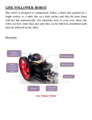
  • 1. LINE FOLLOWER ROBOT This robot is designed to continuously follow a black line painted on a bright surface or a white line on a dark surface and take the turns along with the line automatically. For situations such as cross over where the robot can have more than one path that can be followed, predefined path must be followed by the robot. Overview Line Follower Robot
  • 2. Hardware components required and their purpose 1. Arduino UNO board 2. IR Sensor 3. Comparator 4. DC motor 5. Motor driver IC (L293D) 6. Wheels 7. Power adopter  Arduino UNO board: This is the brain of this robot in which the program is loaded to do the required functioning and is interfaced with sensors and the motor driver to make the system work as required.  IR sensor: This senses whether there is platform in front of the robot or an edge is arrived and sends the appropriate signal to the comparator.  Comparator: This gets input from the sensor, compare it with predefined voltage and send logic 1 to microcontroller if there is detected a still platform and logic 0 if edge of platform is there.
  • 3. IR Sensor Circuit  DC Motor: This motor is controlled with DC voltages and can move in forward and backward direction according to the polarity of the voltage applied.  Motor driver IC (L293D): Microcontrollers can’t supply the current required by DC motor to run. So, to fulfill this requirement these motor driver ICs are used.
  • 4. DC motors with Driver IC  Power adopter: This is used to give appropriate dc power supply to microcontroller, driver IC sensors and the other passive components of the robot.  Wheels: In it three wheels are employed, two at rear end and one at front end. Rear wheels are attached with the motors and also control the steering of robot. Front wheel is the loose steered wheel which moves in the direction of the pressure applied to it.
  • 5. Block diagram Block Diagram: Line Follower Description To make the robot follow the black line, IR sensors are employed with the fact that black surface absorbs light and white surface reflects light. The sensors are mounted on left front end and right front end of the robot keeping the black line lies in between them. Until sensors are getting the reflected light, the comparator sends logic 1 to the microcontroller and the microcontroller in turn switches ON the motor associated with the sensor and when any of the sensors comes up on the black line the microcontroller stops the motor associated with that sensors and make the robot to turn in the direction of the black line. When the robot reaches end point and both the sensors are getting black surface, robot stops.
  • 6. Program: /*left sensor attached to pin 0, right sensor attached to pin 2, left motor attached to pin 5(+ve),6 and right motor attached to pin 7(+ve),8 and*/ int left_sensor=0; int right_sensor=2; void setup() { pinMode(left_sensor, INPUT); pinMode(right_sensor, INPUT); pinMode(5, OUTPUT); pinMode(6, OUTPUT); pinMode(7, OUTPUT); pinMode(8, OUTPUT); } void loop() { char value,v0,v2; v0=digitalRead(0); v2=digitalRead(2); value=((v2<<2)|v0); switch(value) { case 5 { digitalWrite(6, LOW); digitalWrite(8, LOW); digitalWrite(5, HIGH); digitalWrite(7, HIGH); //switch on both
  • 7. break; } case 1: //RIGHT SENSOR'S OUTPUT { digitalWrite(5, HIGH); digitalWrite(7, LOW); digitalWrite(6, LOW); digitalWrite(8, LOW);//switch on only LEFT motor move to RIGHT break; } case 4: //LEFT SENSOR'S OUTPUT { digitalWrite(5, LOW); digitalWrite(7, HIGH); digitalWrite(6, LOW); digitalWrite(8, LOW);//switch on only RIGHT motor move to LEFT break; } case 0: { digitalWrite(5, LOW); digitalWrite(7, LOW); digitalWrite(6, LOW); digitalWrite(8, LOW); //both stop break; } } }
  • 8. Programming Digital I/O pins of Arduino UNO board:  Each pin is controlled by three commands associated with it which are designated as: pinMode() digitalWrite() digitalRead()  pinMode() This configures the specified pin to behave either as an input or an output. Syntax pinMode(pin, mode) Parameters pin: the number of the pin whose mode you wish to set mode: INPUT, OUTPUT. Returns None Example int ledPin = 13; // LED connected to digital pin 13 void setup() { pinMode(ledPin, OUTPUT); // sets the digital pin as output } void loop() { digitalWrite(ledPin, HIGH); // sets the LED on delay(1000); // waits for a second digitalWrite(ledPin, LOW); // sets the LED off
  • 9. delay(1000); // waits for a second }  digitalWrite() Write a HIGH or a LOW value to a digital pin. If the pin has been configured as an OUTPUT with pinMode(), its voltage will be set to the corresponding value: 5V (or 3.3V on 3.3V boards) for HIGH, 0V (ground) for LOW. Syntax digitalWrite(pin, value) Parameters pin: the pin number value: HIGH or LOW Returns None Example Sets pin 13 to HIGH, makes a one-second-long delay, and sets the pin back to LOW. int ledPin = 13; // LED connected to digital pin 13 void setup() { pinMode(ledPin, OUTPUT); // sets the digital pin as output } void loop() { digitalWrite(ledPin, HIGH); // sets the LED on delay(1000); // waits for a second
  • 10. digitalWrite(ledPin, LOW); // sets the LED off delay(1000); // waits for a second }  digitalRead() Reads the value from a specified digital pin, either HIGH or LOW. Syntax digitalRead(pin) Parameters pin: the number of the digital pin you want to read (int) Returns HIGH or LOW Example int ledPin = 13; // LED connected to digital pin 13 int inPin = 7; // pushbutton connected to digital pin 7 int val = 0; // variable to store the read value void setup() { pinMode(ledPin, OUTPUT); // sets the digital pin 13 as output pinMode(inPin, INPUT); // sets the digital pin 7 as input } void loop() { val = digitalRead(inPin); // read the input pin digitalWrite(ledPin, val); // sets the LED to the button's value }